Full Terms & Conditions of access and use can be found at
http://www.tandfonline.com/action/journalInformation?journalCode=ystw20
Download by: [CAPES] Date: 29 June 2017, At: 05:23
Science and Technology of Welding and Joining
ISSN: 1362-1718 (Print) 1743-2936 (Online) Journal homepage: http://www.tandfonline.com/loi/ystw20
Crystallography of Widmanstätten austenite in
duplex stainless steel weld metal
Abtibol J. W. Menezes, H. Abreu, S. Kundu, H. K. D. H. Bhadeshia & P. M. Kelly
To cite this article: Abtibol J. W. Menezes, H. Abreu, S. Kundu, H. K. D. H. Bhadeshia & P. M. Kelly (2009) Crystallography of Widmanstätten austenite in duplex stainless steel weld metal, Science and Technology of Welding and Joining, 14:1, 4-10, DOI: 10.1179/136217108X341166 To link to this article: http://dx.doi.org/10.1179/136217108X341166
Published online: 04 Dec 2013.
Submit your article to this journal
Article views: 135
View related articles
duplex stainless steel weld metal
J. W. Abtibol Menezes
1, H. Abreu
1,2, S. Kundu
3, H. K. D. H. Bhadeshia
*
2and
P. M. Kelly
4Two kinds of austenite grow from
d
-ferrite during the cooling of the duplex stainless steel weld
deposits studied here, Widmansta¨tten plates and allotriomorphs which precipitate at
d
–
d
grain
boundaries. It is found using microtexture measurements that the preferred crystallographic
orientation of the Widmansta¨tten austenite can be estimated using established theory if it is
assumed that there is an interaction between external stress and the growing plates. It is also
demonstrated that the Widmansta¨tten and allotriomorphic forms of austenite may not be
identically oriented even when the former appears to originate from the latter; this may be a
consequence of differences in the transformation mechanisms of these two forms of austenite.
Keywords:Duplex stainless steels, Welding, Crystallography, Texture
Introduction
The combination of good mechanical properties and corrosion resistance of duplex stainless steel is attributed to a microstructure of approximately equal proportions of ferrite and austenite.1,2 The alloys and associated welds are associated with fascinating metallurgy.3–6 Welding disrupts the microstructure through the loca-lised input of heat; duplex steels can become fully ferritic on reaching temperatures in excess of 1250uC; austenite may reform on subsequent cooling but the quantity will depend on the cooling rate. High heat input welds are associated with slower cooling and hence a greater quantity of austenite in the final microstructure. The morphology of the austenite can also vary with the welding conditions; high cooling rates seem to favour the precipitation of Widmansta¨tten austenite.7
Southwick and Honeycomb8,9 concluded that the decomposition of d-ferrite to austenite occurs by two different mechanisms depending upon the transforma-tion temperature. At high temperatures the reactransforma-tion occurs by a diffusional nucleation and growth process whereas at low temperatures the austenite forms by a displacive mechanism on a habit plane close to {1 3 3}d.
However, the mechanism of transformation is not established because the complete set of data needed to show consistency with the phenomenological theory of martensite crystallography has never been assembled.10–12There is some evidence for the partition-ing of solutes durpartition-ing the formation of intragranular
plates of austenite13but the possibility that composition changes occur after transformation cannot be ruled out. Attempts at measuring the surface relief associated with the formation of the Widmansta¨tten austenite show some displacements but the data are qualitative and inconclusive.14
Our aim was to see whether it is possible to detect an interaction of plates of Widmansta¨tten austenite with the stresses that are inevitable when a bead on plate weld cools. The work is conducted using electron backscatter diffraction (EBSD), together with an analysis of the data based on the crystallographic theory of martensitic transformations, although it should be stated at the outset that this in itself may not be sufficient to establish the detailed atomic mechanism.
Experimental
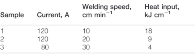
The welds were deposited using AWS 2209-17 electrodes on a 12?7 mm thick plate of DSS UNS S31803 by the shielded metal arc welding process. The chemical compositions of both the base metal and weld metal are presented in Table 1. Table 2 lists the three kinds of welding conditions used.
Behara’s etchant, a solution of 0?3–0?6 g of potassium metabisulfite in 20 mL of HCl and 100 mL of water was used to etch the metallographic samples.
Electron backscattered diffraction analyses were performed using an Oxford Crystal 300 system attached to a Philips XL 30 SEM. For this work, the specimens were mechanically ground and polished, to a final finish using colloidal silica. The microscope used was CAMSCAN Maxim field emission gun SEM, using a magnification of 6500 with a step size of 0?5mm.
Orientation data were acquired from known locations in order to relate the orientation data to strain maps. Subsequent data analysis was carried out using HKL technology ‘Channel5’ software.
1Universidade Federal do Ceara´, Engenharia Metalu´rgica e de Materiais,
Fortaleza, Brazil
2University of Cambridge, Materials Science and Metallurgy, Cambridge,
UK
3TATA Steel, Research and Development Division, Jamshedpur, India 4
University of Queensland, Mining, Minerals and Materials, Australia
Results
The geometry of the bead on plate deposit is illustrated in Fig. 1 and the reference axes marked represent the sample frame of reference, which will be used later in the paper in plotting crystallographic data. The microstruc-ture of duplex stainless steels of the type considered here is generated by transformation from the columnar grains of d-ferrite which form during solidification. Although the details are not entirely established, it is believed that the Widmansta¨tten austenite grows by a displacive mechanism whereas allotriomorphic austenite is considered to be a reconstructive transformation.8 Phase maps, which also illustrate the microstructure, were obtained using EBSD with a pixel size of
d51?89mm (Fig. 2). There were few unsolved points
so the dominant error in the measurement of phase fraction comes from the pixel size. A phase is presumably not detected if it covers less than half of a pixel. On these grounds, the authors estimate that the error is given bySV60?5d, whereSVis the amount ofc/d
interface per unit volume. Taking the worst case scenario of the 4 kJ cm21, S
V was measured to be
,0?12mm21, giving a measurement error in volume
fraction of the order of ¡0?1. The values of volume fraction are indicated in Fig. 2. It is reasonable that the volume fraction of austenite increases with the heat input, since a larger heat input leads to a slower cooling rate.15,16
Crystallography
Figure 3 shows an EBSD image of the austenite together with separate images of d-ferrite, allotriomorphic austenite c and Widmansta¨tten austenite cw; similar
images are available for the other two heat input samples but are excluded for brevity. The number of variants perd-ferrite grain is much smaller than the 24 possible theoretically. The fact that thecandcwcan be
separated on the basis of their Euler angles may be, as
discussed later, significant from the point of view of the mechanism of transformation.
The phenomenological theory of martensite crystal-lography gives a complete description of the mathema-tical connection between the orientation relationship, the habit plane and the shape deformation for each plate that forms by displacive transformation.10–12,17–19 The most common application of this theory is to the transformation of the face centred cubic (f.c.c.) austenite into a body centred cubic (b.c.c.) or body centred tetragonal martensite. Here the authors wish to study the reverse reaction, from the b.c.c. d-ferrite to f.c.c. austenite.
Table 3 lists some crystallographic data for the b.c.c.Rf.c.c. transformation. The data for brass (f.c.c.
a, b.c.c. b) are due to Cornelis and Wayman.20 Calculations based on phenomenological theory depend on the lattice parameter ratio of the parent and product phases. The ratio for brass is similar to that in duplex stainless steel; the X-ray measured lattice parameters of the weld metal were found to be ad52?8894 A˚ and
ac53?6358 A˚ . Two further solutions are also listed in
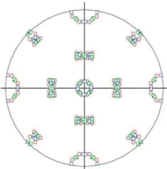
Table 3 from the work of Bowden and Kelly.21,22 The orientation relationships listed as the coordinate trans-formation matrices help predict the transtrans-formation texture as a function of a given parent austenite texture.23–25 Each grain ofd-ferrite can transform into
24 variants ofcw, but it is possible that some variants are
favoured over others due to the development of residual stress as the bead on plate deposit cools. Figure 4 shows a stereogram defined relative to the crystallographic axes of d-ferrite, with {100}c poles for all the orientations
listed in Table 3 together with the expectation from the exact Kurdjumov–Sachs orientation.26The results from all four orientations are similar and experiments of the type reported here probably cannot distinguish between them because as will be seen later, the detected intensity from austenite is diffuse enough to make such distinc-tions difficult. It is probable that the austenite contains dislocations due to the mechanism of transformation and due to plasticity induced by residual stress during the cooling of the weld. When comparing the calcula-tions described later against experimental data on variant selection, best agreement was found using the solutions corresponding to brass and ‘solution 2’, the latter being slightly more consistent. Therefore, the data corresponding to ‘solution 2’ are henceforth used throughout the paper.
Table 2 Welding conditions
Sample Current, A
Welding speed,
cm min21
Heat input,
kJ cm21
1 120 10 18
2 120 20 9
3 80 30 4
Table 1 Chemical compositions, wt-%
Cr Ni Mo N C Mn S P Si Cu Nb Fe
Plate 22?22 5?59 3?08 0?18 0?018 1?48 0?001 0?019 0?45 0?28 0?021 Bal. Electrode 23?0 9?0 3?0 0?15 0?02 0?8 – – 0?8 – Bal. 1 Shape of weld deposited with 18 kJ cm21 of heat input,
with sample reference frame marked
Abtibol Menezes et al. Crystallography of Widmansta¨tten austenite in duplex stainless steel weld metal
Finite element simulations of bead on plate welds27 indicate that the longitudinal stress in the bead (which is the largest component of stress) should be compressive during cooling although the sign may reverse once ambient temperature is reached.28In the present case the transformation fromd-ferrite occurs at temperatures in access of 700uC in which case it is justified to assume that the bead was in compression before transformation.
The effect of this stress on variant selection can be expressed using the Patel and Cohen method,29in which
the interaction of a plate with the stress provides the mechanical driving forceUfor transformation
U~sNfzts (1)
wheresNis the stress component normal to the habit
a4 kJ cm21withV
c<0?41¡0?1; b9 kJ cm21withV
c<0?49¡0?1; c18 kJ cm
21withV
c<0?65¡0?1 2 Phase maps showingd-ferrite as light grey and austenite as dark grey
aEBSD image showing only austenite;bonlyd-ferrite;callotriomorphic austenite;dWidmansta¨tten austenite
plane,tis the shear stress resolved on the habit plane in the direction of shear and f and s are the respective normal and shear strains associated with transforma-tion. The normal and shear stresses on the habit plane can be calculated by resolving the external stress
parallel to p and on to the habit plane in the direction of shear, using the data listed in Table 3, for each possible orientation of an austenite plate. All plates whose shape deformations comply with the compres-sive residual stress along the direction y in Fig. 1 are favoured and included here in the calculation of transformation texture.
Calculations were conducted on all three welds assuming the crystallography consistent with ‘solution 2’, which were then compared against experimental data, assuming that only those variants which comply with the stress (U.0) form, and then repeating the analysis for the those variants which are not favoured (U,0). The experimental data in these comp-arisons are confined to the Widmansta¨tten plates of austenite.
The results are illustrated in Fig. 5 for all three welds; note that using imaging such as that illustrated in Fig. 3, the authors have only used information from the Widmansta¨tten austenite (rather than the allotrio-morphs) in plotting the pole figures. It is evident that most of the observed intensity can be explained if it is assumed that only the 12 favoured variants grow; the minority intensity not explained in this way is consistent with the formation of some unfavoured variants. The latter observation that some plates form which do not comply with the stress is not surprising since in addition to the mechanical driving force, there is a chemical driving force for transformation of d-ferrite which encourages the formation of all 24 variants. It is known that the ratio of the mechanical driving force to total driving force must be large for favoured variants to dominate.24 The chemical free energy change accom-panying the transformation of d-ferrite into an equili-brium mixture of dzc is illustrated in Fig. 6; this is likely to be an overestimate of the driving force because
Table 3 Crystallographic details
Lattice parameters, A˚ Habit plane, displacement vector m
Brass ab52?935 p5(0?17593 0?6596120?73073)b 0?2331
aa53?702 d5(0?1569120?7420420?65174)b
Solution 1 ad52?875 p5(0?5888620?41678 0?69439)d 0?2200
ac53?591 d5(20?47846 0?62846 0?61329)d
Solution 2 ad52?875 p5(20?2095420?70951 0?67282)d 0?2570
ac53?591 d5(20?18506 0?78271 0?59424)d
Brass
a J b
ð Þ~
0:682855 {0:711900 0 :163896 0:721105 0:692808 0:005021
{0:117124 0:114758 0:986465 0 B @ 1 C A Solution 1
d J c
ð Þ~
0:677740 0:723985 0:128506
{0:167069 {0:018574 0:985770 0:716070 {0:689565 0:108367 0 B @ 1 C A Solution 2
d J c
ð Þ~
0:723985 0:689565 0:018574
{0:128506 0:108367 0:985770 0:677740 {0:716070 0:167069 0 B @ 1 C A
ais the lattice parameter of the phase identified by the subscript.p, dandmare the unit normal to the habit plane, the unit
displacement vector and the magnitude of the displacement vector, respectively. (aJb) is the coordinate transformation matrix relating the bases defined by the basis symbolsaandb.
4 Plots of expected positions of {100} poles of austenite relative to crystallographic axes of d-ferrite, assuming brass (black triangles), solution 1 (blue squares), solu-tion 2 (green, inverted triangles) and exact Kurdjumov–Sachs (red circles) orientation relation-ship; poles from both halves of stereographic sphere are plotted
Abtibol Menezes et al. Crystallography of Widmansta¨tten austenite in duplex stainless steel weld metal
the authors do not allow for the strain energy due to the accommodation of the shape deformation accompany-ing transformation, typically the order of 400 J mol21.
The calculations were conducted using MTDATA with the SGTE database30and such calculations are known to be reliable for duplex stainless steels.31 From these data, the chemical free energy is likely to be ten times greater than the mechanical driving force over the approximate transformation temperature range (700– 800uC), although the terms would be much more equal if the strain energy is accounted for.
Allotriomorphic austenite
The authors have not attempted here to predict the orientation of allotriomorphic austenite because it is a reconstructive transformation and hence does not have a shape deformation other than an isotropic volume change, which should only react to hydrostatic stress. A variety of other criteria, such as the optimum orientation for nucleation while in contact with two or more d-ferrite grains, may determine variant selection. Indeed, the strict condition that a line must remain
a U.0, 4 kJ cm21;b U,0, 4 kJ cm21;c U
.0, 9 kJ cm21;d U
,0, 9 kJ cm21; e U
.0, 18 kJ cm21;f U
,0, 18 kJ cm21
invariant during displacive transformation.18,19,32–34 Therefore, it is not surprising that in the present work, a significant difference in orientation was found between the allotriomorphic austenite and Widmansta¨tten aus-tenite, even when the latter appeared to grow from the former (Fig. 7). This result is consistent with the different mechanisms of transformation for the two kinds of austenite.
Conclusion
The crystallographic orientations of Widmansta¨tten austenite in bead on plate welds of duplex stainless steel can be estimated on the assumption that those variants that comply with the stress that develops during the cooling of the weld are favoured. This demonstrates that the transformation interacts in a systematic manner with the applied stress. It is found that even when Widmansta¨tten austenite appears to develop from allotriomorphic austenite, there is a significant relative misorientation between these two morphologies, possi-bly reflecting the fact that the allotriomorphs form by a diffusional transformation mechanism.
Acknowledgement
The authors are grateful to CNPq (National Council for Scientific and Technological Development) for financial support (project no. 200220/2007-1).
References
1. D. N. Noble and T. G. Gooch: ‘Factors controlling the ferrite/ austenite balance in arc welded 22Cr5Ni2?5MoN duplex stainless steel’, Technical Report 321/1986, the Welding Institute, Abington, UK, 1986.
2. L. Karlsson:Anti-corros. Method. Mater., 1995,42, 30–35. 3. W. M. Yip, H. C. Man and W. H. Ip:Sci. Technol. Weld. Join.,
1999,4, 226–232.
4. N. A. McPherson, Y. Li and T. N. Baker:Sci. Technol. Weld. Join., 2000,5, 235–244.
5. V. Muthupandi, P. B. Srinivasan, S. K. Seshadri and S. Sundaresan:Sci. Technol. Weld.Join., 2004,9, 47–52.
6. A. J. Ramirez, S. D. Brandi and J. C. Lippold:Sci. Technol. Weld. Join., 2004,9, 301–313.
7. B. E. S. Lindblom, B. Lundqvist and N. E. Hannerz:Scand. J. Metall., 1991,20, 305–315.
8. P. D. Southwick and R. W. K. Honeycombe: in ‘International conference on martensitic transformations ICOMAT ‘79’, 189–194; 1979, Boston, MIT Press.
9. P. D. Southwick and R. W. K. Honeycombe:Met. Sci., 1980,7, 253–261.
10. J. S. Bowles and J. K. MacKenzie:Acta Metall., 1954,2, 129–137. 11. J. K. Mackenzie and J. S. Bowles:Acta Metall., 1954,2, 138–147. 12. M. S. Wechsler, D. S. Lieberman and T. A. Read:Trans. AIME J.
Met., 1953,197, 1503–1515.
13. S. Atamert and J. E. King:Zietschrift fu¨r Metallkunde, 1991,82, 230–239.
14. N. I. A. Haddad: ‘Development of microstructure in duplex stainless steel welds’, PhD thesis, University of Cambridge, Cambridge, UK, 1989.
6 Calculated change in Gibbs free energy DG5Gczd2Gd
as function of temperature
a orientation image showing location of scan; b
misor-ientation as function of distance; c stereogram
illustrat-ing difference in orientation – blue poles representcw
7 Difference in orientation between cw and associated allotriomorphic austenite (18 kJ cm21weld)
Abtibol Menezes et al. Crystallography of Widmansta¨tten austenite in duplex stainless steel weld metal
15. D. Rosenthal:Weld. J. Res. Suppl., 1941,20, 220s–234s. 16. L.-E. Svensson, B. Gretoft and H. K. D. H. Bhadeshia:Scand. J.
Metall., 1986,15, 97–103.
17. J. W. Christian: ‘Theory of transformations in metal and alloys, part II’, 3rd edn; 2003, Oxford, Pergamon Press.
18. J. W. Christian: ‘Theory of transformations in metal and alloys, part I’, 3rd edn; 2003, Oxford, Pergamon Press.
19. H. K. D. H. Bhadeshia: ‘Geometry of Crystals’, 2nd edn; 2001, London, Institute of Materials.
20. I. Cornelis and C. M. Wayman:Acta Metall., 1974,22, 291–300. 21. P. M. Kelly:Acta Metall., 1965,13, 635–646.
22. H. G. Bowden and P. M. Kelly:Acta Metall., 1967, 15, 1489– 1500.
23. S. Kundu and H. K. D. H. Bhadeshia:Scr. Mater., 2006,55, 779–781. 24. S. Kundu, K. Hase and H. K. D. H. Bhadeshia:Proceed. Roy. Soc.
A, 2007,463A, 2309–2328.
25. H. K. D. H. Bhadeshia, H. Abreu and S. Kundu:Int. J. Mater. Res., 2008,99, 342–346.
26. G. V. Kurdjumov and G. Sachs: Zietschrift fr Physik A Hadrons Nuclei, 1930,64, 325–343.
27. X. Y. Shan, M. J. Tan and N. P. O’Dowd: J. Mater. Process. Technol., 2007,192–193, 497–503.
28. N. P. O’Dowd: Private communication, 2008. 29. J. R. Patel, M. Cohen:Acta Metall., 1953,1, 531–538.
30. NPL: MTDATA: Software, National Physical Laboratory, Teddington, UK, 2006.
31. F. H. Hayes:J. Less–Common Met., 1985,114, 89–96.
32. J. W. Christian and A. G. Crocker: in ‘Dislocations in solids’, Vol. 3, 165–252; 1980, North Holland, Amsterdam, Holland, Elsevier.