ISSN 0104-6632 Printed in Brazil
www.abeq.org.br/bjche
Vol. 30, No. 03, pp. 551 - 562, July - September, 2013
*To whom correspondence should be addressed
Brazilian Journal
of Chemical
Engineering
MASS TRANSFER OF SO
2
ABSORPTION WITH
AN INSTANTANEOUS CHEMICAL REACTION
IN A BUBBLE COLUMN
Xiaolei Li
1, Chunying Zhu
1*, Sumin Lu
2and Youguang Ma
11
School of Chemical Engineering and Technology, State Key Laboratory of Chemical Engineering, Phone: +86 (0) 22 2740 4772, Fax: +86 (0) 22 2740 4772, Tianjin University, Tianjin, 300072, China.
E-mail: [email protected]
2
Department of Material and Chemical, Tianjin Polytechnic University, Tianjin, 300160, China.
(Submitted: April 22, 2012 ; Revised: June 18, 2012 ; Accepted: August 3, 2012)
Abstract - Gas absorption accompanied by an instantaneous irreversible chemical reaction in bubble columns
has been analyzed theoretically. A mass transfer model based on the Dankwerts surface-renewal model as
well as the penetration theory for surface stretch proposed by Angelo et al. was developed, in which the
effects of bulk motion and turbulence on mass transfer were taken into account. The analytical expressions for the time-average mass transfer coefficient and the enhancement factor have been obtained. The fast reactive
absorption of SO2 from gas mixtures into aqueous NH4HCO3 solution was investigated experimentally in a
bubble column reactor to validate the mass transfer model, and the results calculated by the present model agree well with the experimental results.
Keywords: Absorption; Bubble column; Mass transfer; Instantaneous reaction; Enhancement factor.
INTRODUCTION
Gas absorption accompanied by chemical reactions is widely encountered in chemical and allied industries. A number of experimental and theoretical studies on this type of gas absorption process have been reported over the past few decades and many mass transfer models, as well as their corresponding numerical or analytical solutions, have also been developed based on the film theory, the penetration theory or the surface-renewal model (Danckwerts, 1950; Last et al., 2002; da Silva et al., 2007; Danish et al., 2008; Meldon et al., 2007; Kakaraniya et al., 2007; Jun Yue et al., 2012; Zhang
et al., 2012; Martínez et al., 2012). A chemical reaction can be considered to be instantaneous when its rate is much greater than the rate of diffusion. Some typical examples include the removal of
Brazilian Journal of Chemical Engineering
gas absorption accompanied by an instantaneous chemical reaction in a limited gas-liquid system. Jun Yue et al. (2012) also studied gas absorption with instantaneous reaction in a finite liquid layer. However, because the conventional model for gas reactive absorption generally introduced empirical parameters to reflect the effects of the bulk motion and turbulence, it does not reveal the inherent mechanism of the influence of the bulk motion and turbulence on mass transfer between the gas-liquid phases, especially in a bubble column with very complex two-phase flow behavior. Inspired by this point, Angelo et al. (1966) developed the penetration concept in the absence of bulk motion and turbulence and proposed a promising theory called “surface-stretch theory”. Jajuee et al. (2006) further developed the model by incorporating Dankwerts (1951) surface-renewal model with the penetration theory for surface stretch proposed by Angelo et al (1966) and extended the model to liquid-liquid systems.
In this study, a theoretical analysis of gas absorp-tion accompanied by an instantaneous chemical reaction of the type “A + YB = products” is presented taking into account the effects of bulk motion and turbulence. A mass transfer model based on the Dankwerts (1951) surface-renewal model and the penetration theory for surface stretch proposed by Angelo et al. (1966) was developed and analytical solutions have been derived. The mass transfer process of the fast reactive absorption of SO2 into aqueous
NH4HCO3 solution in a bubble column was
experi-mentally investigated to validate the proposed mass transfer model.
EXPERIMENTAL
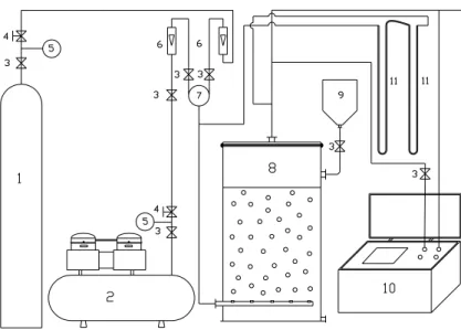
A schematic diagram of the experimental setup, which consisted of the mixing gas generation unit, exhaust detection devices and bubble column, is shown in Figure 1. The bubble column was made of stainless steel and was 20 cm in diameter and 45 cm in height.
SO2 with a volume concentration of 98% (Tianjin
Kermel Chemical Reagent Co., Ltd) supplied from a cylinder was diluted with air from the air compressor (Shanghai Jiebao Compressor Manufacture Co., Ltd.). The two kinds of gases were mixed in the gas mixer. Then the air-SO2 mixture was fed at the bottom of
the column and the SO2 reacted with NH4HCO3
(mass purity > 0.995, Tianjin Kermel Chemical Reagent Co., Ltd) immediately in the liquid phase. Air was fed into the bubble column before the experiments. When the system reached stable conditions, valves (3) and (4) on the SO2 cylinder were opened and the
air-SO2 mixture introduced into the bubble column.
The concentration of SO2 in the exhaust was detected
by the flue gas analyzer (Qingdao Minhope electronic instrument Co., Ltd). The liquid was
sampled at the bottom of the column in the SO2
absorption process in order to measure the pH with a digital pH meter. The experiments were carried out at room temperature and repeated three times. The gas flow rates were controlled by rotameters (LZB-type, Tianjin flow Instrument Co., Ltd.) with the measuring range of 0-100 ml·min-1 for SO2 and
0-100 L·min-1 for air; the accuracy of rotameters was ±1.5%.
1) Sulfur dioxide cylinder;
2) Air Compressor;
3) Valve;
4) Pressure reducing valve;
5) Manometer;
6) Rotor flow meter;
7) Gas mixer;
8) Bubble column;
9) Feed tank;
10)Flue gas detector;
11)Manometer.
Mass Transfer of SO2 Absorption with an Instantaneous Chemical Reaction in a Bubble Column 553
Brazilian Journal of Chemical Engineering Vol. 30, No. 03, pp. 551 - 562, July - September, 2013
THEORIES
Mass Transfer Model
For gas absorption accompanied by an instantane-ous chemical reaction of the type A + YB = products, the heat of reaction could be neglected because of the excellent heat transfer characteristics in the bubble columns when the concentration of the gas-phase reactant is low. It is assumed that diffusion occurs only in the direction perpendicular to the interface. The model describing the process can be stated as follows:
2
A A A
z A 2
c c c
u D
z z
∂ − ∂ = ∂
∂θ ∂ ∂ for 0≤ ≤z zλ (1)
A
0 c 0
IC.θ = ⇒ = for all z
* A
z 0
C A
B . = ⇒c = , z= λ ⇒cA=0, for θ >0
2
B B B
z B 2
c c c
u D
z z
∂ − ∂ = ∂
∂θ ∂ ∂ for zλ≤ ≤ σz (2)
IC. θ = 0 ⇒cB=B* for all z
BC.z= λ ⇒cB=0, z= σ ⇒cB=B*, for θ >0
In the position of the reaction plane, the following equation can be obtained:
A B
A z B z
dc dc
YD D
dz =λ= − dz =λ (3)
According to the surface-renewal model of Danckwerts (1951), the surface-age distribution function is given by ( )φ θ :
S ( ) Se− θ
φ θ = (4)
The film area comprising the elements having ages between θ and (θ + θd ) is ( )dφ θ θ. Let the total area of the surface exposed to the gas be equal to
A( )∞ and A( )θ for the surface areas with ages between θ and (θ + θd ). One can then obtain:
s s
dA( )
( )d Se d d(e )
A( )
− θ − θ
θ = φ θ θ = θ = −
∞ (5)
Eq. (5) may be readily integrated and taking A=A0 at θ =0 gives:
s 0
A( )θ = −A (1 e∞ − − θ)+A (6)
Consider a small flat element of surface x yΔ Δ moving with the fluid bulk velocity, the change in the area of the surface of this flat element with time is:
y y y y y
x x x x x
x(u u )
A
( )
y(u u )
+Δ
+Δ
⎡ Δ − ⎤
∂ ⎢ ⎥
= ⎢ ⎥
∂θ ⎢+Δ − ⎥
⎣ ⎦
(7)
Dividing by x yΔ Δ and taking the limit as xΔ and y
Δ approach zero, Eq. (7) may be rewritten as:
y
x u
ln A u
( )
x y
∂
∂ =∂ +
∂θ ∂ ∂ (8)
For an incompressible fluid, Eq. (8) can take the following form with the aid of the equation of continuity:
z
ln A u
( )
z
∂ = −∂
∂θ ∂ (9)
Since the expression on the left-hand side is independent of z, it may be obtained for negligible net transfer across the interface:
z
ln A
u = −z(∂ )
∂θ (10)
To solve Eqs. (1) and (2), we define the following dimensionless variables:
1 A 0
Z =z D θ (11)
2 B 0
Z =z D θ (12)
0
T= θ θ (13)
*
A A
C =c A (14)
*
B B
C =c B (15)
Brazilian Journal of Chemical Engineering
2
A A A
x,y A 2
1 1
C ln A C C
Z( ) D
T T Z Z
∂ − ∂ ∂ = ∂
∂ ∂ ∂ ∂ (16)
IC. T= ⇒0 CA =0 for all Z
BC.Z1= ⇒0 CA =1,
1 1 A 0
Z = λ = λ D θ ⇒CΑ =0
2
2
B B B
x,y B 2
2
C ln A C C
Z( ) D
T T Z Z
∂ − ∂ ∂ = ∂
∂ ∂ ∂ ∂ (17)
IC. T= 0 ⇒CB=1 for all Z
BC.
1
'
2 B 0 B
Z = λ = λ D θ ⇒C =0,
2 1 B 0 B
Z = σ = σ D θ ⇒C =1
In order to solve these equations, combinations of the variables are introduced to convert the partial differential Eqs. (16) and (17) to simple differential equations:
( )
A A 1
C =C φ CB=CB
( )
φ2 (18)where
( )
1 Z1 G T
φ = × φ =2 Z2×G T
( )
(19)Eqs. (16) and (17) thus become:
2 x,y '
A A
1
2 2 3
1 1
ln A
( )
d C T G dC
0 d
d G G
∂
⎡ ⎤
⎢ ∂ ⎥
+ φ ⎢ − ⎥ φ =
φ ⎢ ⎥
⎣ ⎦
(20) for 0≤ φ ≤ φ1 1,λ
2
2 x,y '
B B
2
2 2 3
2 ln A
( )
d C T G dC
0 d
d G G
∂
⎡ ⎤
⎢ ∂ ⎥
+ φ ⎢ − ⎥ φ =
φ ⎢ ⎥
⎣ ⎦
(21) for φ ≤ φ ≤ φ2,λ 2 2,σ
where G indicates the partial derivative of G with ' respect to T at constant Z. It has been assumed that:
' x,y
2 3
ln A
( )
G T
G G
∂
⎡ ⎤
⎢ ∂ − ⎥= α
⎢ ⎥
⎢ ⎥
⎣ ⎦
(22)
where α is an arbitrary constant. The following assumption was also made:
x,y ln A
( ) F
T
∂ =
∂ (23)
Eq. (22) may be rearranged to:
3
FG− = αG ' G (24)
Eq. (24) is a Bernoulli equation, which can be put into linear form by the following substitution:
1 2
G=h− (25)
By using Eq. (25), Eq. (24) takes the form:
dh
2Fh 2
dT= − + α (26)
The integrating factor can be introduced:
(
ln A)
2 dT
2 FdT T 2
e ∫ =e ∫∂ ∂ =A(T) (27)
Combining Eqs (26) and (27), one obtains:
( )
2dh dA 2 2
A 2hA 2 A d A h 2 A
dT = − dT+ α ⇒ = α (28)
Eq. (28) can be integrated:
T
2 2
5 0
A h= α2
∫
A(T) dT+C (29)Eq. (29) in transformed form becomes:
( ) ( )
T( )
5 0G T =A T 2α
∫
A T dT+C (30)where C5 is a constant.
Then the solutions of Eqs. (20) and (21) are (Mehra, 1990):
(
)
A 1 2 1
Mass Transfer of SO2 Absorption with an Instantaneous Chemical Reaction in a Bubble Column 555
Brazilian Journal of Chemical Engineering Vol. 30, No. 03, pp. 551 - 562, July - September, 2013
(
)
B 3 4 2
C =C +C erf 2 αφ 2 (32)
where C1, C2, C3 and C4 are constants. If the assumed
combinations of variables are successful, equations (23) and (24) should satisfy the initial and boundary conditions of Eqs. (16) and (17).
( )
AC 0 =1 CA
( )
φ1,λ =0 (33)( )
B 2,
C φ λ =0 CB
( )
φ2,σ =1 (34)According to the literature (Jajuee et al., 2006), for convenience α=2 is taken. Thus, C5 in Eq. (30)
should be zero to satisfy Eq. (33). Combining Eqs. (31) and (33) yields:
( )
( )
A 1 1,
C = −1 erf φ erf φ λ (35)
Combining Eqs. (32) and (34) leads to the following relation:
( )
( )
( )
( )
( )
( )
2, B 2, 2, 2 2, 2, erf C erf erf erf erf erf λ δ λ δ λ φ = −φ − φ
φ +
φ − φ
(36)
From Eq. (35) one gets:
( )
12( )
* *
A A A
*
1, A 0
c C C Z
A A
z z Z z
G T 1 2 A e erf D −φ λ ∂ = ∂ = ∂ ∂ = ∂ ∂ ∂ ∂
− ⋅ φ ⋅
π θ
(37)
From Eq. (36) the following equation can be obtained:
( )
( )
( )
2 2
* *
B B B
*
2, 2, B 0
c C C Z
B B
z z Z z
G T
1 2
B e
erf erf D
−φ
δ λ
∂ = ∂ = ∂ ∂ =
∂ ∂ ∂ ∂
⋅
φ − φ π θ
(38)
At the position of the reaction plane, , substituting Eqs. (37) and (38) leads to the function for the change of the position of the reaction with time:
( )
( )
( )
2 1, 2 2, * A 2, 2, * B 1, Y D Ae erf erf
D B e erf λ λ −φ δ λ −φ λ
⎡ φ − φ ⎤
⎣ ⎦
= φ
(39)
The instantaneous rate of gas absorption for a surface element may be defined by:
A A,z A,z
dA
dN j j ( )d
A∞
= = φ θ θ (40)
where
*
A A
A,z A z 0 A Z 0
c C Z
j D D A
z = Z = z
∂ ∂ ∂
= − =
∂ ∂ ∂ (41)
Hence
( )
( )
* A A 1, S A 0 1 2dN D A
erf
1
G T Se d
D λ
− θ =
φ π
⋅ ⋅ ⋅ ⋅ θ
θ
(42)
Eq. (42) can be integrated to get the average flux over the time of exposure per unit area of turbulent surface:
( )
( )
(
)
2
* A S
A
0 1,
0 *
L
2 S D 1
N A G T e d
erf
K A 0
∞ − θ
λ
= ⋅ ⋅ ⋅ θ
φ πθ
= −
∫
(43)
The time-average mass transfer coefficient can be obtained:
( )
( )
2 S A L 0 1, 0 2 S D 1K G T e d
erf
∞ − θ
λ
= ⋅ ⋅ ⋅ θ
φ πθ
∫
(44)Brazilian Journal of Chemical Engineering
( )
1,( )
2,erf φ λ =erf φ λ (45)
The function for the variation of the position of the reaction plane with time may be obtained:
( )
( )
A B
A B
1 D 1 D
* *
A B
1, * 1 D * 1 D
A B
2,
Y D A e D B e
erf
1 Y D A e D B e
erf
− −
λ − −
δ
φ =
+
φ (46)
By substituting Eq. (46) into Eq. (44), the mass transfer coefficient is found to be:
( )
( )
A B A B
1 D * A
1 D * B
L * 1 D
A 1 D * B
S A
0 2, 0
Y D A e 1
D B e K
Y D A e
D B e
D S 1 2 S
G T e d
erf − − − −
∞ − θ
δ +
=
⋅ ⋅ ⋅ θ
π
∫
φ θ(47)
The expression for the mass transfer coefficient is too complicated to be employed for practical purposes due to the error function in the equation. But when the scale of turbulence is high, Jajuee et al. (2006) found that the integrand in Eq. (47) had the value of 2. The scale of turbulence in bubble columns is high; thus the expression of mass transfer coefficient becomes:
A B
A B
1 D 1 D
* *
A B
L * 1 D * 1 D
A B
A
1 Y D A e D B e
K
Y D A e D B e
4D S
− −
− −
+ =
π
(48)
Harriott (1962) pointed out that the concept of surface-renewal theory could only be expected when
H DS<0.5 is met, where H is the average
distance to which eddies approach the interface. Thus, the distance from the interface to the bulk of the liquid is equal to H plus the length of eddies:
H l
δ = + (49)
The length and velocity scales of eddies for isotropic turbulence can be calculated from:
( )
3 1 4l= k ε (50)
( )
1 4 kυ = ε (51)
where k is the kinematic viscosity:
k= μ ρ (52)
ε is the viscous dissipation of energy per unit mass of eddies, which can be calculated from (Wang et al., 2005):
g
g L
g
U U g
1
⎛ ε ⎞
ε =⎜⎜ − − ε ⎟⎟
⎝ ⎠ (53)
where Ug is the superficial gas velocity, UL the
superficial liquid velocity and εg the gas hold-up. For bubble columns with low superficial liquid velocity, UL can be regarded as zero and the energy dissipation
rate can be obtained:
g U g
ε = (54)
The fractional rate of surface renewal may be defined as follows (Jajuee et al., 2006):
s= υ l (55)
For mass transfer accompanied by chemical reaction, one of the most important parameters is the enhancement factor, defined as the ratio of the time-mean mass flux at the interface with chemical reaction to the time-mean mass flux at the interface without chemical reaction under the same driving force.
*
L L
E=K K (56)
The time-mean mass flux at the interface without chemical reaction is (Jajuee et al., 2006):
L
*
A
K = 4D S π (57)
Substitution of Eqs. (48) and (57) into Eq. (56) yields:
A B
1 D 1 D
* *
A B
1
E 1
Y D A e− D B e−
Mass Transfer of SO2 Absorption with an Instantaneous Chemical Reaction in a Bubble Column 557
Brazilian Journal of Chemical Engineering Vol. 30, No. 03, pp. 551 - 562, July - September, 2013
Bubble Column Model
In this experiment, low superficial gas velocities were applied, which was in the bubble flow regime. The heat of reaction can be neglected due to the low sulfur dioxide concentration and the excellent heat transfer characteristics of bubble columns. Thus, the mass balance of sulfur dioxide in the gas phase is:
(
)
2 2 2
2
2
SO SO SO
b g 2
L,tol
SO L
G
C C C
u D
t z z
K a
HC RC
Hε
∂ + ∂ = ∂
∂ ∂ ∂
− −
(59)
The mass balance of sulfur in the liquid phase is:
(
2)
2
L,tol
L L
L 2 SO L
G
K a
C C
D HC RC
t z 1 ε
∂ = ∂ + −
∂ ∂ − (60)
where the total mass transfer coefficients are given by the following equation:
*
L,tol L G
1 1 1
K =EHK +k (61)
The gas-side volumetric mass transfer coefficient can be calculated from (Cho et al. 1988):
3 0.5 0.76
G G b
k a=2.6 10 D× u (62)
Before the NH4HCO3 is consumed completely,
CL in Eqs. (59) and (60) is zero and E is calculated
from Eq. (58). After the NH4HCO3 is consumed
completely, CL is the total sulfur concentration in the
liquid:
2
2 3 3
L SO ,L HSO SO
C =C +C −+C − (63)
The following reactions in the bulk liquid should be considered:
2 3
2 2 2 3 3
1 H HSO SO
SO H O H SO H HSO
K C +C − C
+ −
+ = = +
= (64)
2
3 3
2
3 3
2 H SO HSO
HSO H SO
K C +C − C −
−= ++ −
= (65)
2
3 3
2 2 3
3 H CO HCO
CO H O H HCO
K C +C − C −
+ −
+ = +
= (66)
2
3 3
2
3 3
4 H CO HCO
HCO H CO
K C +C − C −
− = ++ −
= (67)
2
w H OH
H O H OH
K C +C −
+ −
= +
= (68)
3 4
4 3 2
6 NH OH NH
NH OH NH H O
K C C −C +
++ − = +
= (69)
The charge balance in the liquid is as follows:
2
4 3 3 3
2 3
NH H HSO SO HCO
CO OH
C C C 2C C
2C C
+ + − − −
− −
+ = + +
+ + (70)
Combining Eqs. (63)-(65) leads to:
2
SO ,L L
C =RC (71)
where
(
)
2 2
1 1 2
H H H
R=C + C + +K C + +K K (72)
and E is calculated from (Bokotko et al., 2005):
2 2 2
3 1 SO SO ,L SO
HSO
E= +1 D −K D ( C + C ) (73)
The chemical reaction equilibrium constants at 25 °C are shown in Table 1.
2
SO D
3
HSO
D − and
3
HCO
D −
are respectively 1.83×10⁻⁹ m2·s-1, 1.545×10⁻⁹ m2·s-1 and 1.185×10⁻⁹ m2·s-1 at 25°C (Ebrahimi et al., 2003). The Henry coefficient is 0.8082 atm·kg·mol-1 (Ebrahimi et al., 2003).
Table 1: The chemical reaction equilibrium constants
Parameter K1 K2 K3 K4 K5 K6
Brazilian Journal of Chemical Engineering
Dispersion coefficient (Meikap et al., 2002), liquid phase:
b
1.5 0.3
L R
D =0.678d u and
b
1.5 0.3 R
d u <400 (74)
Dispersion coefficient (Meikap et al., 2002), gas phase:
1.5
g R b G
D =50d u ε (75)
Bubble rising velocity (Moo-Young et al., 1981):
2
b b
u = ρg d 18μ (76)
where the mean diameter of the bubbles:
1/2 1/3
b 0 e0
d =0.18d R (77)
e0 G 0 G
R =4Qρ π μd and Re0<2000 (78)
Gas holdup (Meikap et al., 2002):
(
2) (
1 8 3 2 2)
1 12g R L L R L L
b R
0.25 d g gd
u gd
ε = ρ δ ρ μ
(79)
Interfacial area per unit volume (Meikap et al., 2002):
(
)
0.51b L
a=48.7 u μ (80)
The reactor height was discretized in a spatially uniform grid and the finite difference method was applied. These coupled partial differential equations were solved numerically by using Matlab.
RESULTS AND DISCUSSIONS
In the bubble column model, the liquid-side mass transfer coefficient for the absorption of SO2 into
aqueous NH4HCO3 solution was calculated from
Eqs. (57) and (58). The comparisons between the calculated results and the experimental results for the
fast reactive absorption of SO2 into aqueous
NH4HCO3 solution in the bubble column under
different operating conditions were made and are shown in Fig. 2-4. It can be seen that the calculated results agree well with the experimental results, which verifies that the mass transfer model based on the aforementioned scheme is reasonable and accurate.
Effect of the Inlet SO2Concentration
Figure 2 shows the effect of the inlet SO2
concentrations on the gas absorption. It can be found from Fig. 2 that the duration time for complete SO2
removal decreases with the increase of the inlet SO2
concentration; in the last period of SO2 absorption,
the outlet SO2 concentration increases more
significantly with the increase of the inlet SO2
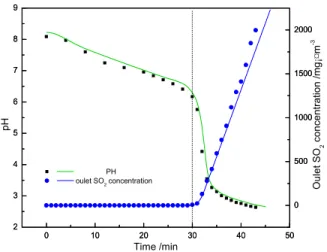
concentration. The outlet SO2 concentration and the
pH value of the bulk liquid are plotted against time in Figure 3. It can be seen that the pH value decreased sharply from 6.17 to 3.55 upon absorbing
a small amount of SO2 at the thirtieth minute
approximately and the outlet SO2 concentration
increased more and more quickly from 0. This indicated that NH4HCO3 in the liquid phase was
consumed completely and the absorption process changed from a fast chemical reaction to a weak one. Thus, the absorption rate becomes smaller and the outlet concentration gradually increases.
0 10 20 30 40 50
0 500 1000 1500 2000 2500
0 10 20 30 40 50
0 500 1000 1500 2000 2500
2.6785 5.3571 6.6964 8.0357
O
u
le
t
SO
2
c
o
n
c
e
n
tr
a
ti
o
n
/
m
g
·
m
-3
Time /min
Inlet SO2 concentration g·m -3
Figure 2: Effect of the inlet SO2 concentrations on
the outlet SO2 concentrations (concentration of
ammonium 0.05%, gas flow rate 20 L·min-1). Scatter plots for experimental results and smooth curves for the modeling results.
Effect of the Concentration of NH4HCO3
The effect of the concentration of NH4HCO3 on
the gas absorption was presented in Fig. 4. From Fig.
4, the duration time for complete SO2 removal
increased with the increase of the concentration of NH4HCO3. This is because when the concentration
of NH4HCO3 is high, more SO2 must be introduced
into the system to react completely with NH4HCO3.
Mass Transfer of SO2 Absorption with an Instantaneous Chemical Reaction in a Bubble Column 559
Brazilian Journal of Chemical Engineering Vol. 30, No. 03, pp. 551 - 562, July - September, 2013
increased with the increase of the concentration of NH4HCO3.
0 10 20 30 40 50
2 3 4 5 6 7 8 9
0 10 20 30 40 50
2 3 4 5 6 7 8 9 0 500 1000 1500 2000 0 500 1000 1500 2000 PH oulet SO2 concentration
p H Time /min O u le t SO 2 c o n c e n tr a ti o n / m g ¡¤ m -3
Figure 3: Variation of the outlet SO2 concentrations
and pH value varying with time (concentration of the inlet SO2 was 2.6785 g·m-3, concentration of
ammo-nium bicarbonate 0.05%, gas flow rate 20 L·min-1). Scatter plots for experimental results and smooth curves for the modeling results.
0 10 20 30 40 50 60
0 500 1000 1500 2000
0 10 20 30 40 50 60
0 500 1000 1500 2000 0.20% 0.15% 0.10% 0.05% O u le t SO 2 co n c e n tr a ti o n / m g ¡¤ m -3
Time /min
Concentration of NH4HCO3
Figure 4: Effect of concentrations of ammonium bicarbonate solution on the outlet SO2 concentrations
(inlet concentration of SO2 was 2.6785 g·m -3
, gas flow rate 20 L·min-1). Scatter plots for experimental results and smooth curves for the modeling results.
Effect of the Gas Flow Rate
Figure 5 presents the effect of the gas flow rate on the gas absorption. It can be seen from Figure 5 that the duration time for complete SO2 removal
decreased rapidly with increasing gas flow rate. In the last period of the SO2 absorption, the outlet SO2
concentrations increased more significantly as the gas flow rate increased. According to Eq. (76), increasing the gas flow rate makes the bubbles’ rising velocity higher, which contributes to a very high fractional rate of surface renewal, liquid-side mass transfer coefficient, gas holdup and interfacial area. Thus, NH4HCO3 is consumed quickly and the
duration time for complete SO2 removal becomes
shorter. In the last period of the SO2 absorption, the
absorption process is actually water absorbing SO2,
and therefore the higher the gas flow rate, the faster the concentration of SO2 in the liquid phase increases.
Thus, the outlet SO2 concentrations increase more and
more quickly with the increase of the gas flow rate.
0 10 20 30 40 50 60
0 500 1000 1500 2000 2500
0 10 20 30 40 50 60
0 500 1000 1500 2000 2500 20 30 60 O u le t SO 2 co n ce n tra ti o n / m g · m -3 Time /min
Gas flow rate L·min-1
Figure 5: Effect of the gas flow rate on the outlet SO2 concentrations (inlet concentration of SO2 was
5.3571 g·m-3, concentration of ammonium bicarbonate 0.05%. Scatter plots for experimental results and smooth curves for the modeling results.
CONCLUSION
Brazilian Journal of Chemical Engineering
coefficient of the reaction. The time-average mass transfer coefficient is correlated with the fractional rate of surface renewal and influenced by the bubble rising velocity. The fast reactive absorption of SO2
into aqueous NH4HCO3 solutions with different
concentrations in a bubble column was experimen-tally investigated. An absorption model accompanied by fast chemical reaction has been developed and numerically solved. The prediction results agree well with the experimental results, which validates the mass transfer model proposed.
ACKNOWLEDGMENTS
We gratefully acknowledge the financial support for this project from the National Natural Science Foundation of China (No 21076139), and the Program of Introducing Talents of Discipline to Universities (Grant No B06006).
NOMENCLATURE
a specific interfacial surface m2·m-3
A exposed area of
time-dependent surface
m2 A0 initial area of the surface
exposed to gas
m2 A∞ total area of the surface
exposed to gas
m2
A* saturation concentration of A mol·L-1
B* saturation concentration of B mol·L-1
C molar concentration at the
interface
mol·L-1
cA molar concentration of
species A
mol·L-1 cB molar concentration of
species B
mol·L-1
CA dimensionless concentration
profile defined by Eq. (14)
CB dimensionless concentration
profile defined by Eq. (15)
Ci constant
CL concentration of the total
sulfur in the liquid
mol·L-1 CSO2, L concentration of SO2 in the
liquid
mol·L-1
DA diffusivity of A m2·s-1
DB diffusivity of B m2·s-1
Dg dispersion coefficient, gas
phase
m2·s-1 DL dispersion coefficient, liquid
phase
m2·s-1
DG diffusivity in the gas phase m
2
·s-1
2
SO
D diffusivity of SO2 in the
liquid phase
m2·s-1
3
HSO
D − diffusivity of 3 HSO− in the liquid phase
m2·s-1
3
HCO
D − diffusivity of HCO3− in the liquid phase
m2·s-1
dR column diameter m
g gravitational acceleration m·s-2
G defined by Eq. (19)
h defined by Eq. (25)
H average distance of
approach of eddies to the interface
m
JA molar flux of diffusion of
species A relative to the molar average velocity
mol·m-2·s-1
kG gas side mass transfer
coefficient
m·s-1
kL fluid-film mass transfer
coefficient
m·s-1 Ki reaction rate constant (i=1,
2, 3, 4, 5, 6)
KL time-average mass transfer
coefficient in the liquid phase
m·s-1
KL,tol total mass transfer
coefficient of SO2
m·s-1
l length scale of eddies in the
viscous dissipation range
m
NA overall flux of species A
relative to a phase boundary
mol·m-2·s-1
R defined by Eq. (72)
Re0 the orifice Reynolds number
S fractional rate of surface
renewal
s-1
T dimensionless time variable
defined by Eq. (13)
ug superficial gas velocity m·s-1
ul superficial liquid velocity m·s-1
x rectangular coordinate m
y rectangular coordinate m
z rectangular coordinate m
Z1 dimensionless position
variable defined by Eq. (11)
Z2 dimensionless position
variable defined by Eq. (12)
Greek Letters
α defined by Eq. (22)
ε energy dissipation rate per
unit mass
Mass Transfer of SO2 Absorption with an Instantaneous Chemical Reaction in a Bubble Column 561
Brazilian Journal of Chemical Engineering Vol. 30, No. 03, pp. 551 - 562, July - September, 2013
εG gas hold-up
θ time s
θ0 characteristic constant
defined for bubble column system
s
kinematic viscosity m2·s-2
G viscosity of gas phase kg·m
-1
·s-1
L viscosity of liquid phase kg·m-1·s-1
ρG gas density kg·m-3
ρL liquid density kg·m-3
σ distance from the interface
to the bulk of the liquid
m
σ1 dimensionless distance from
the interface to the bulk of the liquid
σL surface tension of the liquid N·m-1
υ molar average velocity;
velocity scale of eddies in viscous dissipation range
m·s-1
Φ1 defined by Eq. (19)
Φ2 defined by Eq. (19)
Subscripts
A gas phase reactant
B liquid phase reactant
REFERENCES
Angelo, J. B., Lightfoot, E. N., Howard, D. W., Generalization of the penetration theory for surface stretch: Application to forming and oscil-lation drops. AIChE J., 12, 751-760 (1966). Bokotko, R. P., Hupka, J., Miller, J. D., Flue gas
treatment for SO2 removal with air-sparged
hydrocyclone technology. Environ. Sci. Technol., 39, 1184-1189 (2005).
Cho, J. S., Wakao, N., Determination of liquid-side and gas-side volumetric mass transfer coefficients in a bubble column. J. Chem. Eng. Jpn., 21, 576-581 (1988).
da Silva, E. A. B., Souza, D. P., de Souza, A. A. U., de Souza, S. M. A. G. U., Prediction of effective diffusivity tensors for bulk diffusion with chemi-cal reactions in porous media. Braz. J. Chem. Eng., 24, 47-60 (2007).
Danish, M., Sharma, R. K., Ali, S., Gas absorption with first order chemical reaction in a laminar falling film over a reacting solid wall. Appl. Math. Model., 32, 901-929 (2008).
Danckwerts, P. V., Unsteady-state diffusion or heat-conduction with moving boundary. Trans. Faraday Soc., 46, 701-712 (1950).
Dankwerts, P. V., Significance of liquid-film coeffi-cients in gas absorption. Ind. Eng. Chem., 43, 1460-1467 (1951).
de Lind van Wijngaarden, G., Versteeg, G. F., Beenackers, A. A. C. M., Mass-transfer enhance-ment factors for reversible gas–liquid reactions: Comparison of DeCoursey’s and Onda’s methods. Chem. Eng. Sci., 41, 2440-2442 (1986).
Ebrahimi, S., Picioreanu, C., Kleerebezem, R., Heijnen, J. J., van Loosdrecht, M. C. M., Rate-based modelling of SO2 absorption into aqueous
NaHCO3/Na2CO3 solutions accompanied by the
desorption of CO2. Chem. Eng. Sci., 58,
3589-3600 (2003).
Garg, R., Nair, S., Bhaskarwar, A. N., Mass transfer with instantaneous chemical reaction in finite gas-liquid systems. Chem. Eng. J., 76, 89-98 (2000).
Harriott, P., A random eddy modification of the penetration theory. Chem. Eng. Sci., 17, 149-154 (1962).
Jajuee, B., Margaritis, A., Karamanev, D., Bergougnou, M. A., Application of surface- renewal-stretch model for interface mass transfer. Chem. Eng. Sci., 61, 3917-3929 (2006).
Kakaraniya, S., Kari, C., Verma, R., Mehra, A., Gas absorption in slurries of fine particles: SO2
-Mg(HO)2-MgSO3 system. Ind. Eng. Chem. Res.,
46, 1904-1913 (2007).
Last, W., Stichlmair, J., Determination of mass transfer parameters by means of chemical absorption. Chem. Eng. Technol., 25, No. 4, 385-391 (2002). Martínez, I., Casas, P. A., Simple model for CO2
absorption in a bubbling water column. Braz. J. Chem. Eng., 29, 107-111 (2012).
Mehra, A., Gas absorption in slurries of finite-capacity microphases. Chem. Eng. Sci., 45, 1525-1538 (1990).
Meikap, B. C., Kundu, G., Biswas, M. N., Modeling of a novel multi-stage bubble column scrubber for flue gas desulfurization. Chem. Eng. J., 86, 331-342 (2002).
Meldon, J. H., Olawoyin, O. O., Bonanno, D., Analysis of mass transfer with reversible chemical reaction. Ind. Eng. Chem. Res., 46, 6140-6146 (2007).
Moo-Young, M., Blanch, H. W., Design of bio-chemical reactors mass transfer criteria for simple and complex systems. Adv. Biochem. Eng./ Biotechnol., 19, 1-69 (1981).
Brazilian Journal of Chemical Engineering
Yue, J., Rebrov, E. V., Schouten, J. C., Enhancement factor for gas absorption in a finite liquid layer. Part 1: Instantaneous reaction in a liquid in plug flow. Chem. Eng. Technol., 35, No. 4, 679-692 (2012).