ISSN 0104-6632 Printed in Brazil
www.abeq.org.br/bjche
Vol. 33, No. 01, pp. 133 - 143, January - March, 2016 dx.doi.org/10.1590/0104-6632.20160331s00002780
Brazilian Journal
of Chemical
Engineering
MULTIVARIABLE OPTIMAL CONTROL
OF A HEAT EXCHANGER NETWORK
WITH BYPASSES
F. Delatore
1*, L. F. Novazzi
3, F. Leonardi
2and J. J. da Cruz
4 1Department of Electrical Engineering, FEI University, Av. Humberto de Alencar Castelo Branco 3972, Zip Code: 09850-901, Sao Paulo - SP, Brazil.
Phone: +55 11 43532900 E-mail: [email protected] 2
Department of Mechanical Engineering, FEI University, Sao Paulo - SP, Brazil. 3
Department of Chemical Engineering, FEI University, Sao Paulo - SP, Brazil. 4
Department of Telecommunications and Control, University of Sao Paulo, Sao Paulo - SP, Brazil.
(Submitted: June 18, 2013 ; Revised: December 23, 2014 ; Accepted: February 2, 2015)
Abstract - Heat exchanger networks present an interesting control problem due to coupling among process streams. In this work, the linear quadratic regulator (LQR), a feedback optimal control technique, is used to control stream temperatures on a laboratory scale heat exchanger network, through bypass manipulation, in a multivariable system. The LQR design was based on a mathematical model of the plant and its performance was compared to traditional PID control and to dynamical decoupling. Experimental tests were performed to evaluate the controllers, involving regulatory and servo problems. The performance of the different controllers was quantitatively compared by using the integral absolute error. Although LQR is not a new control methodology, the results obtained in this work suggest that LQR is an interesting alternative to control HEN when compared to the PID and to the dynamic decoupler. Moreover, one of the main advantages of the LQR is its tuning simplicity, since only one parameter is sufficient for this application.
Keywords: Heat exchanger network; Optimal control; LQR.
INTRODUCTION
Due to the oil price rise since the seventies and to environmental issues, efficient use of energy in chemical processes is very important. Almost thirty years ago the theoretical foundations of Process Inte-gration for the efficient use of energy were estab-lished, with Pinch Technology, an elegant approach to set energy / cost targets for heat exchanger networks (HEN), as well as rules to design such networks (Linhoff et al., 1982). Nowadays these synthesis tech-niques, including some which are based on mathe-matical programming, are well established in Process
Design and are easily found in many Chemical Engi-neering textbooks.
consid-134 F. Delatore, L. F. Novazzi, F. Leonardiand J. J. da Cruz
Brazilian Journal of Chemical Engineering
ering process operability and controllability, which they called process resilience. Operability is defined as the ability of the network to remain steady-state feasible when subjected to process disturbances, whereas controllability is regarded as the network capacity to go from one steady-state to a different one, in a finite time.
Later on, Calandranis and Stephanopoulos (1988) proposed a sequence of control actions of the loops in a network to solve the regulatory and servo control problems in a HEN, exploiting its structural charac-teristics. The idea of the strategy was the identifica-tion of routes through the HEN that could allocate disturbances or setpoint changes to available sinks, i.e., utility heat exchangers.
Based on a previous work on HEN control by Ma-thisen (1994), Glemmestad et al. (1996) applied a method for optimal operation of the network and studied the coupling of manipulated variables, repre-sented by bypasses positions on the exchangers, with controlled variables, represented by stream target temperatures. In addition to the input / output pairing in the suggested decentralized control scheme, the proposed approach also contemplated the optimiza-tion of utility consumpoptimiza-tion in the HEN, since the number of manipulated variables is greater than the number of controlled parameters, which resulted in a positive degree of freedom. More recently and due to this positive degree of freedom, Sun et al. (2013) used non-square relative gain arrays to choose which bypasses should be selected to control a HEN.
Glemmestad et al. (1999) presented an alternative approach to the optimal operation of HEN systems based on on-line optimization of a steady state func-tion and a fixed control structure. Later, Giovanini and Marchetti (2003) showed that a low-level Dis-tributed Control System is also capable of handling HEN control problems when a flexible control loop structure is provided.
In the work of Lersbamrungsuk et al. (2008), a linear programming (LP) problem for the optimal operation of a HEN was formulated. As a conse-quence of the LP problem, the optimal point of oper-ation of a HEN remained at some of its constraints. The authors also proposed an offline strategy to switch between active constraints, identifying possi-ble operational regions, and combined this with de-centralized control. Previously, Aguilera and Mar-chetti (1998) developed a procedure for optimization and control of a HEN, in a more complex approach than the latter, since a nonlinear programming problem (NLP) needs to be solved online, during operation.
From the point of view of performance, there are a lot of different control techniques that could be
used in heat exchanger networks. These techniques range from methodologies that have a complex and highly engineered design, typically with a superior performance, down to methodologies that are easy and effortless to design, but normally not capable to lead to a desirable performance. As an example, the PID is the most common controller due to its straight-forward design procedure and easy implementation.
Nonetheless, in multivariable control problems, as is the case of a HEN, the PID design will demand a supplementary engineering effort to tune well the controllers. In this situation, model predictive control (MPC) may be considered to be a suitable control strategy to be used within industrial process, as it can deal with multivariable systems, complex dynamics and constraints on input and/or output variables. In this approach the future moves of the manipulated variables depend on the model and on plant meas-ured output variables, in such a way that an on-line constrained optimization is performed.
Gonzalez et al. (2006) presented an application of optimization and control of heat exchanger networks, through a two-level control structure. In the lower level, a constrained MPC was used and the higher level was supervised by an online optimizer. The MPC was based on a linear approximate plant model whereas the optimizer was based on a rigorous model. By using a moving horizon, hard constraints on the manipulated variables were dealt with in a straightforward way. Although the proposed method-ology uses a consolidated control strategy, just simu-lated results were presented. Besides, modeling er-rors were not explicitly included in the design.
In the range of suitable controllers for the control of a HEN, one can also point out the Linear Quadratic Regulator (LQR), which has a very simple design in the time domain. During the design of a LQR, the expected dynamic response is explicitly not taken into account, and the closed-loop response is checked afterwards. If the time response does not present an acceptable performance, it is possible to try a new controller by changing the penalty matri-ces, resulting in an extraordinary ease to design, and normally a good performance (Delatore et al., 2009).
perfor-m cl m so w dy w st (L an w th sp h is tu th (3 d cr d d b w E ca d mance found losed loop co
THE
The shell most commo ome particu with their low
ynamic mod written based treams, as Luyben, 199 nd C stand f while T is the he stream flo
pecific heat, eat transfer c s the volume ube length.
H H
H
T m
t v
C C
C C
T m
t v
Equations he finite diff 3) and (4), w
iscretized te retization cel
, 1 2 H i C dT a dt a T
, 1C n i dT a dt In addition ehavior of s was also mod Equations (5) ates bypass a
, 5 Hby i dT a T dt
d for the LQ ontrol on a H
MATHEM
and tube he n HE used ular characte w cost and del of a shell
on the energ in Equation 90). In these
for the hot a e stream tem owrate, ρ its
z is the axia coefficient, A
e and ν is a
H H
H H
T
v z
C
C C
T U
z V
(1) and (2) ference meth where the su emperature a
lls used, whe
2 , 1
, 2 ,
H i
C n i C n
a T a T
4 , 1 4
3 4 ,
H i
C n
T a T
a a T
n to Equation stream bypa deled and dis ) and (6), w and f is the b
, 1 5
Hby i H
T a T
QR control HEN. MATICAL M at exchanger in chemical eristics, mai uncomplica and tube ex gy balances f ns 1 and 2
equations, th and cold side mperature, t is s density, Cp al position, U A is the heat
ratio betwe
,H
H H p H
UA T V C
, HC p C
UA
T T
C
) were discr hod, resultin ubscript i is and n is the ere i = 1,2,..,
1 2
,1
H
i
a a T
, 3 1 H i iT a a
ns (1) and (2) sses in the scretized, wh where the sub bypass fractio , Hby i T to perform MODEL
rs (HE) are l plants due inly associa ted repair. T xchanger can
for hot and c 2, respectiv he subscripts es, respective s the time, m Cp is the stre
U is the ove transfer area een volume a
H C
T T
C
T
retized throu ng in Equatio connected t number of d
n.
i
4 C n i,
a T
), the dynami heat exchan hich resulted bscript by in on. the the e to ated The n be cold vely s H
ely,
m is
eam rall a, V
and (1) (2) ugh ons o a dis-(3) (4) ical nger d in ndi-(5) dT wh 1 a 3 a 5 a by str Fig tiv fer sol gle too etc Ni of the Mo spa sys fra exp att con fur ste err do in as so , 1
Cby n i T a dt here,
1 Hn m f
1C
n m f
/
H H
n m f
Thus a HE y the intercon
ructure. The gure 1 for t vely (Novazz rential equati lved numeric Figure 1: THE CONT Classical co e output (SI ols, such as c., as well as
chols plots. Multiple Inp e use of su
odern contro ace model a stems (Levi amework is perimental h tenuation cor nsidered as p rthermore, st ep changes in
rors and wit es not cause
It is import relation to o the dynamic that one ca
6 Cby n i,
a T a
/
H H H
f V
/
C C C
f V
HVHby
,EN can be m nnection of H
discretization the first, i-th zi, 2007). Th ions, constitu cally. Discretized h TROLLER C ontrol techni ISO) system Laplace tra s on graphica Nevertheless put Multiple uch techniqu
ol design tec are generally ine, 2010).
applied to d heat exchan rresponding part of the p tream outlet n the setpoin h a smooth actuators sa ant to compa other typical c decoupler an verify if
6 Cby n i, 1
a T
, a2UA/ 2
, a4 UA/
a6n m fC
mathematicall HE, accordin n scheme is h and n-th s he system of uted by 4n e
heat exchang
CHARACT
iques for sin ms are based
ansforms, Ro al tools, such s, for the con Output (MI ues may be chniques bas
more suitab In this wo design the co ger network to inlet tem erformance
temperature nts with sma transient res aturation.
are the propo l control alte
and classica the LQR is
(6
,
2H HV Cp H
2C CV Cp C,
/
C C Cby
f V
ly represente ng to the HE
represented stages, respe f ordinary di equations, w
ger model.
TERISTICS
ngle input si on analytic outh criterio h as Bode an ntroller desig IMO) system troublesom sed on a stat ble for MIM ork, the LQ ontroller in a k. Disturban mperatures a specification es must follo all steady-sta sponse, whic
13 ch o a v is ou in re fo al n te ac du v m T co ou F Y Y G G w Y Y 36
hoice. In the f these typic
) Dynamic D
In multiva ariables are s the influen
utput yi. The nput uj on o ectly related orm of the c
llows it to b aike and Ray ems with cro
ctions in con The techni uce the effe ariables, allo made in a dec The decouplin
ompensating utput and th Figure 2 (Ogu
Based on F
1 11
11
Y s G
G G
2 21 2Y s G
G
Let the tra
12 1 11 G GI G 21 2 22 G GI G The new without the in
1 11
Y s G
2 22
Y s G
e next three s al alternative
Decoupler
ariable syste typically co nce of the in e cross-coup ther outputs to it. The di ouplings tha be controlled y, 1994). Th oss-coupling ntrol loops.
ique of varia ects of existi owing the tun centralized m
ng can be ac g transfer ma he input of unnaike and Figure 2, one
12 2 1
1 12 2
G GI U
GI G U
22 2
21 1 22
G GI U
GI G ansfer functio transfer fun nteractions be 12 21 22 G G G 12 21 11 G G G F
sections, a sh es and of LQ
ems, the inp oupled. The
put ui on its pling is the i
, rather than irect couplin at appear in s d in a simple he difficulty i g, because th
able decoupl ing cross-co ning of the c manner by sca
chieved by a atrix between f the plant,
Ray, 1994). e can write:
2 s s
1 2 U s U sons GI1 and G
nctions of th etween the v
1 U s
2 U s F. Delatore, L. F. N
Brazilian Jou
hort descript QR is present
put and out direct coupl s correspond nfluence of n the output ng is the desi
systems sinc er form (Ogu is found in s hey cause int
ling aims to ouplings amo controllers to
alar controlle adding a pro
n the contro as depicted
GI2 be:
(
he system, n variables, are
(
(
Novazzi, F. Leon
urnal of Chemica
tion ed. tput ling ding the di-ired e it un- sys- ter- re-ong o be ers. oper ller d in (7) (8) (9) 10) now : 11) 12) com in ple mo ity sta sca PID b) str nec res Ro tro hea tio and C g int tem and I K c)
nardiand J. J. da C
al Engineering
Although t mpletely eli practice th etely, since odel, which y. The decou and-alone ba alar design t D controller.
Figure
PID Contro
When subj ream outlet t cted directly sponse with otea and Mar ol is the best
at exchanger on (13), wher d KI is the in
I C K s s These autho tegral contro mperature jumd on process
1 0.739 I d K LQR Contr
Let the syst Cruz
the techniqu iminate inter his decouplin the techniqu is not an ex upling system
asis. After a technique is
.
2: Dynamic
ol
jected to b temperature y to this by a small tim rchetti (1997) option to co r with bypas re gC is the c ntegral gain.
ors proposed oller that de
mp K1 of a s
s dead time α
rol
tem be given
ue theoretica ractions amo ng may not ue is based xact represen m is usually applying the normally us
decoupling s
bypass man in a heat ex ypass presen me delay (No
) showed tha ontrol the tem sses, as indic controller tra
d a tuning fo epends only step response
αd, as follows
n in state-spac
ally is able ong variable t occur com
on a proce ntation of rea
not used on e decoupler,
ed to design
system.
ipulation, th xchanger co nts a lead la
ovazzi, 2007 at integral co
mperature in cated in Equ ansfer functio
(13
ormula for th on the initi e in the bypa s:
(14
d d
y
w th w la
J
w th th
u
fo (L by
K
w R
A
fu ti T T co ou g ou re
Q
su in an co
J
d
x t Ax
dt
y t Cx t
where x is the he output ve with appropr aw that minim
0
T
J
x twhere Q = Q
he state and he linear stat
u t Kx t
orming the Levine, 2010
y:
1 T
K R B P
where P = P
Riccati Algeb
T
A PPAP
Since the L unction rega ion is alway Thus, they ar These matric ontrols and c ut a penalty ive importan utputs y(t) a ewrite the ma
0
T y C Q C
Q
uch that the n the cost fu nd Qz penali
ost function
0
T y
J y Q y
t Bu t
e state vecto ector and A, riate dimens mizes the per
T
Qx t u t
QT ≥ 0 and R
control weig e feedback:
so-called 0). The state
PT ≥ 0 is the braic Equatio
1 T
PBR B P
LQR ensures ardless of the ys optimal i re the tuning
es impose p can be used
cross betwee nce only to th and their int
atrix Q as:
0
Qz
variables y a unction, wher
izes the integ can be writte
T
z
y z Q z
or, u is the in
B, C are co
sions. The o rformance in
T
t Ru t dt
= RT > 0 ar ghting matric
linear quad feedback ma
e solution of on:
0
Q
s the minimi e Q and R v in the mathe g parameters penalties on
in diagonal f en variables. he states asso tegral z(t), it
and z are exp re Qy penali
gral of the ou en as:
T
u Ru dt
(
nput vector, y
onstant matri optimal cont ndex:
t (
re, respective ces, is given
(
dratic regula atrix K is giv
(
f the follow
(
ization of a c alues, the so ematical sen s of the desi
the states a form, i.e., wi If one wants ociated with
t is possible
(2
plicitly includ izes the outp utputs. Thus
(2
15)
y is
ices trol
16)
ely, n by
17)
ator ven
18)
wing
19)
cost olu-nse. ign. and ith-s to
the e to
20)
ded puts the
21)
all Du val equ pen un ma all tw sta loo a s the
Fig sta
are vec use pla at
al.
Fig set
ris
a x
In this work l states to pr ue to the sym
lues have th ually penaliz nalties, whic nique constan atrix, not on ly be obtaine ween speed o ate vector ca
op using the state observe e setpoints fo
gure 3: Fee ate setpoints
A more com e defined no
ctor y. In th ed, where th ant output is
low frequenc , 2009; Dela
gure 4: Feed tpoints and in
Extra states e to an exten
( ) ( )
( )
a
x t t
z t
k, an identic revent satura mmetry of t he same cha zed too. By a ch in this ca nt value as a ly can a des ed, but also of response annot be full LQR gain m er as shown or all states.
dback system included in t
mmon situat ot for the st his way a m he error betw integrated in cies, as show atore et al., 2
dback system ntegrator bloc
s are thus ad nded state xa:
cal penalty is ation of any the problem aracteristics,
appropriately ase means to a common fa sired time re
a satisfactor and control ly measured, matrix K can in Figure 3,
m with state the loop.
ion occurs w tates x but f modified stru ween the set n order to inc wn in Figure
010).
m with state ob ck included i
dded to the s :
s proposed f internal stat and since th controls we y choosing th
o find just a factor in the
esponse gene ry tradeoff b effort. If th , the feedbac be built usin where xSP a
e observer an
when setpoin for the outp ucture can b tpoint and th crease the ga
4 (Delatore
bserver, outp in the loop.
system, givin
(22
for te. he ere he an
Q
er- be-he ck ng are
nd
nts put be he ain
et
put
ng
13
w
d d
sp
K
th
d d
w
A
B
n
fo th m tu si d 38
where:
( ) ( )
d
z t y t
dt
The state pondingly pa
a x
K K K
By taking he state mode
( )
a a
d
x t A x
dt
where:
0 0
a A A
C
0
a B B
Thus, the ew matrices
Before pre ormance app he physical mining the m
urbance varia idered in thi
iagram.
Figu
( )
Cx t
feedback ma artitioned as:
z
K
into accoun el in Equatio
( ) (
a a
x t B u t
augmented used in the L
METHO
esenting the plied to a HE arrangement manipulated,
ables of the s work, as s
ure 5: The HE
F
atrix Ka can :
nt Equations on (15) can b
)
t
matrices Aa LQR project
ODOLOGY
control desi EN, it is imp
t of the exc the controlle experimenta shown in Fig
EN basic stru
F. Delatore, L. F. N
Brazilian Jou
(2
n thus be cor
(2
(22) and (2 be rewritten a
(2
(2
(2
and Ba are .
ign and its p ortant to def changers, det ed and the d al network c gure 5 in a g
ucture.
Novazzi, F. Leon
urnal of Chemica
23)
rre-24)
23), as:
25)
26)
27)
the
per-fine
ter- dis- on-grid
exc H2 pic
dis ana
me ho wh on pa tra are wi net and is c con wh val
nardiand J. J. da C
al Engineering
The experim changers (HE 2) and one cture of the p
Fig
The manipu sturbance va
alyses are lis
Controlled v
TCOUT1: inte
TCOUT2: col
Manipulate
fc1: bypass v
fc2: bypass v
Disturbance
THIN1: hot s
THIN2: hot s
TCIN: cold s
mC: cold str
Figure 7 pr entation diag t streams H hereas the c nes. The basi sses volum ansmitters (T e also two ve
th electric re twork, the c d vessels are convenient t ntrolled by here 0 V rep
lve full open Cruz
mental HEN E1 and HE2 cold stream physical pilot
gure 6: Expe
ulated input ariables of t sted below:
variables:
ermediate co d stream out
d variables: valve positio valve positio
e variables: stream 1 inle stream 2 inle stream inlet t ream flowrat
resents a sim gram (P&ID) H1 and H2 a cold stream ic instrument metric flowm TT) and press essels (V1 an esistances. T connections, e made of A to mention th a signal ran presents a va n.
is constitute 2) and has tw m (C1). Figu t HEN used
erimental setu
ts, controlled the HEN to
old stream tem tput temperat
on, heat exch on, heat exch
t temperatur t temperatur temperature
e
mplified pipin ) for the pilo are indicated C1 is indic tation of the meters (FT), sure indicato nd V2) used The heat exch
pumps (P1 ANSI 304 sta hat the bypas nging from 0
alve full shu
ed by two he wo hot (H1 an
ure 6 shows in this work.
up.
d outputs an o perform th
mperature ture
hanger 1 hanger 2
e e
ng and instr ot plant, whe d by red lin cated by blu e plant encom , temperatu ors (PI). The to heat wate hangers in th 1, P2 and P ainless steel.
sses valves a 0 up to 10 ut and 10 V
eat nd a .
nd he
ch H h u an eq ti co su S eq th an T th w p an o Some char hangers HE HEN plant ar ave the sam ted in a trian nd 1 pass in qual to 0.1 m Table 2 pr ions in the H
old stream C upply tempe
pecific heat qual to 4180 Table 3 pr he heat exch nd outlet tem The overall h
hrough stead was consider ointed out th nd TCOUT2, a
f 28.5 ºC and
Figure 7
Table 1:
Table 2: St
Stream H1 H2 C1 Variable Di NT LT DS A racteristics o 1 and HE2 e presented i me dimension ngular pitch. n the shell, w m2.
resents some HEN, for ho C1, where m
eratures and of hot and c 0 J·kg-1·K-1.
resents nomi hangers HE1 mperatures o heat transfer dy-state expe red for both hat the two c assume nom d 30.0 ºC, re
7: P&ID of t
: Heat excha
ream nomin
m / (kg·
0.154 0.154 0.165 Descr tube d numb tube le shell d area
f the shell an used in th in Table 1. B ns and the tu There is 1 p with a heat
nominal ope ot streams H stands for f
Tout for targe cold streams
inal operatin 1 and HE2, of the hot an
coefficient U
riments and h exchangers controlled va inal operatin spectively. the experime anger chara nal operatin
s-1) Tin / ºC 4 55.0 4 55.0 5 26.9
ription V
diameter 0 er of tubes ength 0 diameter 0
nd tube heat he experimen Both exchang ubes are distr pass in the tub
transfer area
erational con H1 and H2 a flowrate, Tin et temperatur
was conside
ng conditions including in nd cold stream
U was obtain the same va s. It should ariables, TCO ng temperatu
ntal HEN.
acteristics.
g conditions
C Tout / ºC 53.4 53.3 30.0 Value Uni 0.006 m 7 0.750 m 0.060 m 0.1 m2
ex-ntal gers rib-bes a A
ndi-and for res. ered s in nlet ms. ned alue be OUT1 ures s. C e ate lat str flo com cha and the fun cho tha in LQ wh for wa and Q wh ou wh pro on pro sta tim the eve sm pro ben inh pro of tak ven it 2
Table 3: He
Heat exchanger
HE1 HE2
Three exper e the control tory problem ream H2 tem owrate mC, an mbined wit anges in con d disturbanc e servo prob nctions. The osen to avoi at the variatio
the accuracy
RES
The applica QR and appl here a Luenb
r state estim as added to d R matrices
4 27 10 . x I here I is the ut that the co
hich was cho ocedure, usin nly one tunin ocedure coul
The target ate decouple me in a rang e system co en faster th mall when c ocess equipm
nefits: by se herently pre ovide higher
sensor noise The gain va ken as KT eq nt numerical
eat exchange
Tin / ºC
hot cold
55.0 28.5 55.0 26.9
rimental tests system: two m, with dis mperature, T
nd one test i th a regula ntrolled vari es on mC. Ei blem, change amplitudes o d bypass sat ons of the con y range of the
SULTS AND
ation of the ied to the H berger obser mation and a the integral s were chosen
27
x R
I 2identity ma ntroller has osen as 10-4, ng numerical ng paramete ld also have b
performance d system wi e from 200 uld be tune han that, this
compared to ment’s. Besid etting a not event satur r robustness e.
alue of the an qual to 10, a
l problems. S
er nominal c
Tout / ºC
hot cold
53.4 30.0 53.3 28.5
s were perfor o of them inv
sturbances in
THIN2, and in
involving a s atory one,
iables TCOUT ither in the re es were cons of these step turation and ntrolled varia e measuremen
D DISCUSSI
control struc HEN is show
rver was use an anti-wind
action. The n as:
2 2x
atrix. It shou a single desi , through a t l simulation. r, an experi been used. e was to ach
ith a closed to 300 seco d to achiev s amount of o the dynam des, the appro
so fast resp ration of t
and reduce
nti-windup s value high e Simulations u
conditions.
U / W·m-2·K
420 420
rmed to eval volving a reg n supply h n cold strea servo proble with setpoi
T1 and TCOU egulatory or sidered as ste p changes we
in such a wa ables would b nt instrument
ION
cture based o wn in Figure
ed in the loo dup subsyste e weighting
uld be pointe ign paramete trial and err Since there mental tunin
hieve a stead loop consta nds. Althoug e steady sta f time is st mics of mo oach has som ponse, it ma the actuator amplificatio
14
m m je ac
F co
p to In co co th
a
T
w 3
T
re le la ti th th F ti 2 by W an sy H 5
40
mathematical mance for se
ection with a cteristics of t
Figure 8: LQ ontrol.
As for the ler, the tunin o Equation ( n the next ontrol strate ompared to t his work.
) Disturban
THIN2
To evalua with disturban
.0 ºC was ap
THIN2 was inc
esponses of T
ers, where th ated to LQR ively. Figure hree controll he same colo Figure 9, the ions until 50 8.5 ºC and 3 ypass valve When a distur
nd TCOUT2 w
ystem, as ca HEN (Figure
00 s.
model prod etpoint chang a control effo
the bypass va
R controller
PID control ng parameter 13), with an sections the egies (dynam
the LQR, the
ce in Hot St
ate the perfo nces in hot s pplied to THIN
creased to 5
TCOUT1 and T
he black, gr R, PID and d
e 10 indicate lers for bypa or patterns o plant was in 00 s, with T
30.0 ºC, respe s were clos rbance in TH
will be affe an be noted 5) and in th
F
duced a satis ges and for ort compatibl
alves.
structure pro
ller and the d rs were desi
integral gain e performanc mic decouple e proposed ap
tream Inlet T
ormance of stream H2, a
IN2 at 500 s, i
8.0 ºC. Figu
TCOUT2 for th
een and red dynamic dec es the contro asses fc1 and f
of Figure 9. A n nominal o
TCOUT1 and T
ectively. Unt sed, as seen
HIN2 is impose
ected, indica in the grid he responses
F. Delatore, L. F. N
Brazilian Jou
sfactory perf disturbance e with the ch
oposed for H
dynamic dec gned accord n equal to 0. ce of comm er and PID) pproach used
Temperatur
the controll a step change .e., temperat ure 9 shows he three contr d curves are coupler, resp ol effort of
fc2 and follo
As indicated perating con
TCOUT2 equal
til this time, n in Figure ed, both TCO ating a coup diagram of in Figure 9
Novazzi, F. Leon
urnal of Chemica
for- re-
har-EN
ou-ding
.04. mon ) is d in
re
lers e of ture the
rol- re- pec-the ows d in
ndi-l to the 10.
OUT1
pled the , at
Fig tur
Fig tur
con bac bu on tro wa LQ wi sho han pa dy
TC
add tur a q dif lut Tab IA
T
nardiand J. J. da C
al Engineering
gure 9: Plot rbance on TH
gure 10: Con rbance in TH
It can be se ntrol system ck to their s ut with differ n which contr oller opened ay, as indicat QR controlle thout saturat own by the b nd, the dyna ss, fc2, and f
ynamic decou
COUT2 by the
dition to the res observed quantitative fferent contro te Error or IA ble 4 present AE for LQR, P
0 28 28.5 29 29.5 30 30.5 31
T
e
m
p
e
rat
ur
e (º
C
)
TCOUT1 LQR TCOUT2L
0 0 1 2 3 4 5 6 7 8 9 10
Val
v
e Op
enni
ng
(
V
ol
ts
)
LQR - fci1 LQR - fc
Cruz
ts of TCOUT
HIN2.
ntrol effort o
HIN2.
een from the m pushes the
steady-state rent transien roller is used d both bypas ted by the gre er also put i
tion, but in a black lines i amic decoup
fc1 was kept
upler tried to manipulatio e dynamic be d in Figure 9
performance ollers. In thi AE (Ogunnai ts the control PID and the d
500 T
LQR TCOUT1 PID T
500 T ci2 PID - fci1 PID
responses u
of bypass val
e plots in Fig e controlled nominal ope nt performan d. The multi-sses valves, een lines in F into action b
a more aggre in Figure 10 pler actuated shut. This m o control bo on of only o ehavior of TC
, it is import e criterion to is work the I ike and Ray, llers’ perform dynamic dec
1000 Time(s)
TCOUT2 PID TCOUT1 De
1000 ime (s)
D - fci2 Decoupling - f
under step di
lves under di
gure 9 that th d temperatur
erating value nce, dependin
-loop PID co in a smoo Figure 10. Th both bypasse
essive way, . On the oth d only one b means that th
th TCOUT1 an
one bypass.
TCOUT temper tant to speci o compare th Integral Abs
1994) is use mance based o
oupler.
1500
ecoupling TCOUT2Deco
1500 fci1 Decoupling - fci2
is-he res es, ng n-oth
he es, as her y-he nd In ra-ify
he so-ed.
on
oupling
Table 4: Controller performance under disturbance in THIN2.
TCOUT
1 TCOUT2
LQR 169.6 268.1 PID 132.8 187.2
Decoupling 202.5 364.9
By observing the performance of the Integral Ab-solute Error for the three controllers (Table 4), one can see that the PID has the best response for TCOUT1
and also for TCOUT2. However, even with a more
vigorous action, the LQR controller also showed a good performance when compared to the PID. These results suggest that the tuning parameter in Q, which multiplies the identity matrix, and chosen as Q equal to 10-4·I for the LQR design, seems to be high and leded to a faster control action when compared to the PID and dynamic decoupler.
It is worth noting that the PID and the decoupler controllers have more tuning parameters than LQR, which has only one, as considered in this work. Since this value is the unique design parameter in the controller, it is simpler to tune than the PID and the dynamic decoupler.
b) Servo and Regulatory Problem
To evaluate the servo problem in the experimental HEN, the setpoints of TCOUT1 and TCOUT2 were
re-duced 0.5 ºC at a time t equal to 500 s, i.e., TCOUT1
and TCOUT2 were set to 28.0 ºC and 29.5 ºC,
respec-tively. Besides, to evaluate the servo problem and also the regulatory problem, an increase in cold stream flowrate mC of 0.010 kg/s was imposed at 1000 s. Figure 11 shows the responses of TCOUT1 and
TCOUT2, where the black, green and red curves are
related to LQR, PID and dynamic decoupler, respec-tively. Figure 12 indicates the control effort of the three controllers.
By observing Figures 11 and 12, one can see that until 500 s the plant was under nominal operating con-ditions, with TCOUT1 and TCOUT2 equal to 28.5 ºC and
30.0 ºC, and the bypasses valves completely closed. After the setpoint change at 500 s, the plots in Figures 11 and 12 suggest a relatively smooth perfor-mance for setpoint tracking, as well as for disturb-ance rejection, which was imposed at 1000 s.
This behavior is quantitatively indicated in Table 5, by using the IAE criteria. Since there is a setpoint decrease at 500 s, the bypass valves tend to open until 1000 s, when an increase in mC takes place, disturbing both TCOUT1 and TCOUT2, and then the
bypasses begin to close. It can be observed that LQR action is fast when compared to the PID and the
de-coupler controller, leading to a quick setpoint track-ing and also disturbance rejection. This fact can be noted in Table 5, where LQR presents the smallest IAE among the three controllers.
Figure 11: Plots of TCOUT responses under setpoint change and flowrate disturbance.
Figure 12: Control effort of bypass valves under set-point change and flowrate disturbance.
Table 5: Controller performance under setpoint change and flowrate disturbance.
TCOUT1 TCOUT2
LQR 371.9 340.9 PID 431.8 374.3
Decoupling 458.9 366.9
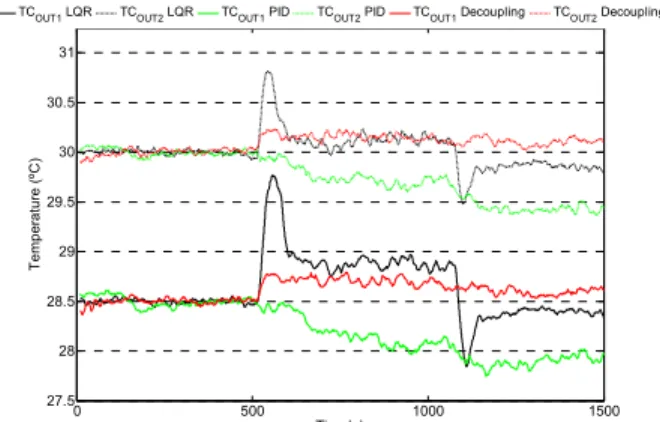
c) Disturbance in Cold Stream Flowrate mC
To evaluate a disturbance rejection in cold stream flowrate mC, a variation from 0.165 kg/s to 0.135 kg/s was imposed at a time t equal to 500 s and then re-moved at 1200 s. The responses of TCOUT1 and TCOUT2
for the three controllers are shown in Figure 13, where the black, green and red curves are related to LQR, PID and dynamic decoupler, respectively. As previ-ously mentioned in Table 3, setpoints of TCOUT1 and
0 500 1000 1500
27.5 28 28.5 29 29.5 30 30.5
Time(s)
T
em
per
at
ur
e (
ºC
)
TCOUT1 LQR TCOUT2 LQR TCOUT1 PID TCOUT2 PID TCOUT1 Decoupling TCOUT2 Decoupling
0 500 1000 1500
0 1 2 3 4 5 6 7 8 9 10
Time (s)
Va
lv
e Oppe
ni
ng (Vo
lt
s
)
142 F. Delatore, L. F. Novazzi, F. Leonardiand J. J. da Cruz
Brazilian Journal of Chemical Engineering TCOUT2 are equal to 28.5 ºC and 30.0 ºC. Figure 14
indicates the control effort of the three controllers, using the same color patterns as in Figure 13.
It can be seen from the plots in Figure 13 and 14 that the LQR controller reacted fast, and opened both bypass valves near 500 s, when the cold stream flow-rate increased. When the flowflow-rate in C1 returned to its nominal operating value, at 1200 s, once more the LQR was fast and drove the controlled variables to 28.5 ºC and 30.0 ºC. Table 6 presents the controllers performance based on IAE for LQR, PID and the dynamic decoupler.
Figure 13: Plots of TCOUT responses under step dis-turbance in mC.
Figure 14: Control effort of bypass valves under dis-turbance in mC.
Table 6: Controller performance under disturbance in mC.
TCOUT1 TCOUT2
LQR 403.9 145.9 PID 431.3 374.3
Decoupling 160.5 132.9
For the first controlled variable, TCOUT1, the
de-coupling technique shows the best performance and
the LQR is slightly better than the PID. As for
TCOUT2, the decoupler has once more the best
perfor-mance and the LQR is much better than the PID. Although the LQR was not the best option in this test, it is still a reasonable choice, due to its tuning simplicity.
CONCLUSIONS
In this work the use of a linear quadratic regulator to control heat exchanger networks was studied. This control technique is an alternative approach which presents advantages in HEN control: the LQR con-troller is easily designed and its performance can be even better than more common control techniques, such as PID and the dynamic decoupler. The aim of the proposed approach is not to accomplish a better performance than the one typically obtained with model predictive control techniques. On the other hand, the LQR can be designed just by using an ap-proximate plant model and only one tuning parame-ter, which can be iteratively chosen.
The approximate dynamic plant model used in the design of the LQR was based on energy balance equa-tions, which were linearized and their order reduced. However, this dynamic model could also be obtained directly from plant operation, in a more straightfor-ward way and probably with equivalent results.
The LQR was applied to a lab scale heat ex-changer network, constituted by two heat exex-changers with two hot and one cold stream. Manipulated vari-ables were the bypass valve positions and the con-trolled outputs were outlet temperatures. The LQR tuning parameter was determined by simulation and the controller performance was compared to the PID and the dynamic decoupler. The controllers’ perfor-mance was quantitatively assessed by the integral ab-solute error and this index showed that the LQR per-formed well both in regulatory and servo problems.
ACKNOWLEDGEMENTS
The authors wish to thank all the institutional support of FEI University.
REFERENCES
Aguilera, N. and Marchetti, J. L., Optimizing and controlling the operation of heat-exchanger net-works. AIChE J., 44 (5), 1090-1104 (1998). Calandranis, J. and Stephanopoulos, G., A structural
approach to the design of control systems in heat
0 500 1000 1500
27.5 28 28.5 29 29.5 30 30.5 31
Time(s)
T
e
m
p
era
tur
e (º
C
)
TCOUT1 LQR TCOUT2 LQR TCOUT1 PID TCOUT2 PID TCOUT1 Decoupling TCOUT2 Decoupling
0 500 1000 1500
0 1 2 3 4 5 6 7 8 9 10
Time (s)
V
a
lv
e Open
ni
ng (V
ol
ts
)
exchanger networks. Comp. Chem. Eng., 12(7), 651-669 (1988).
Delatore, F., Cruz, J. J., Leonardi, F. and Novazzi, L. F., Multivariable Control of a Heat Exchanger with Bypasses. 11th IASTED, Cambridge, UK (2009).
Delatore, F., Cruz, J. J., Leonardi, F. and Novazzi, L. F., Multivariable Optimal Control of a Heat Ex-changer Network (HEN) with Bypasses. 12th IASTED, Banff, Canada (2010)
Giovanini, L. L. and Marchetti, J. L., Low-level flexible structure control applied to heat ex-changer networks. Comp. Chem. Eng., 27, 1129-1142 (2003).
Glemmestad, B., Mathisen, K. W. and Gundersen, T., Optimal operation of heat exchanger networks based on structural information. Comp. Chem. Eng., 20 (suppl.), S823-S828 (1996).
Glemmestad, B., Skogestad, S. and Gundersen, T., Optimal operation of heat exchanger networks. Comp. Chem. Eng., 23, 509-522 (1999).
Gonzalez, A. H., Odloak, D. and Marchetti, J. L., Predictive control applied to heat exchanger net-works. Chem. Eng. Processing, 45, 661-671 (2006). Lersbamrungsuk, V., Srinophakun, T., Narasimhan,
S. and Skogestad, S., Control structure design for optimal operation of heat exchanger networks. AIChE J., 54 (1), 150-162 (2008).
Levine, W. S., The Control Handbook. 2nd Edition, CRC Press, Boca Raton (2010).
Linhoff, B., Townsend, D. W., Boland, D., Hewitt, G. F., Thomas, B. E. A., Guy, A. R. and Marsland, R. H., A User Guide on Process Integration for the Efficient Use of Energy. Warwick Printing Company Ltd., Birmingham (1982).
Luyben, W. L., Process Modeling, Simulation and Control for Chemical Engineers. McGraw-Hill, Singapore (1990).
Marselle, D. F., Morari, M. and Rudd, D. F., Design of resilient processing plants - II. Chem. Eng. Sci., 37(2), 259-270 (1982).
Mathisen, K. W., Integrated Design and Control of Heat Exchanger Network. Ph.D. Thesis, Univ. of Trondheim, Norway (1994).
Novazzi, L. F., Dynamics and Control of Heat Ex-changer Networks. Ph.D. Thesis, Univ. of Campi-nas, Brazil (2007). (In Portuguese).
Ogunnaike, B. A. and Ray, W. H., Process Dynamics, Modeling and Control. Oxford University Press, New York (1994).
Rotea, M. A. and Marchetti, J. L., Integral control of heat-exchanger-plus-bypass systems. IEEE Int. Conf. on Control Applic., Hartford, USA (1997). Sun, L., Luo, X., Hou, B. and Bai, Y., Bypass