VERIFICATION OF THE EFFECT OF CONCRETE SURFACE
PROTECTION ON THE PERMEABILITY OF ACID GASES
USING ACCELERATED CARBONATION DEPTH TEST
IN AN ATMOSPHERE OF 98% CO2
MICHAL STEHLÍK, JIŘÍ NOVÁK*
Brno University of Technology, Faculty of Civil Engineering, Department of Building Testing, Veveří 95, Brno 602 00, Czech Republic
*SYNPO a.s., S. K. Neumanna 1316, Zelené předměstí, Pardubice 532 07, Czech Republic
E-mail: stehlik.m@fce.vutbr.cz
Submitted December 11, 2009; accepted December 21, 2010
Keywords: Carbonation of concrete, Epoxy dispersion, Diffusion, Phenolphthalein test, Concentrated 98% CO2
Carbonation is one of the corrosion processes negatively inluencing the properties of mature concrete. It is caused by a chemical reaction between carbon dioxide iniltrating the surface of a concrete structure and the minerals of the mastic cement. The surface of a concrete structure can be protected from the effects of atmospheric CO2 by coating with modern
waterborne epoxy dispersions. Out of the four types of dispersions tested (dispersion A – CHS Epoxy 200 V 55 + hardener Telalit 180, 2 layers; dispersion B – DOW XZ 92 533 + hardener XZ 92 441.01, 2 layers; dispersion C – CHS Epoxy 200 V 55 + hardener Telalit 180, 1st layer + Epostyl 217 V, 2nd layer; dispersion D – Epostyl 217 V, 2 layers), the type A solvent-based epoxy dispersion and the type C combination of the solvent-based and the solvent-free emulsions demonstrated the highest degree of protection of cement mortar. The effect and actual protection time was evaluated by means of the „accelerated carbonation depth test in 98% CO2“.The correlation dependence found in the so-called ”accelerated test“ enables us to
determine intervals of real time in the natural environment of 0.03% CO2 corresponding to the intervals of accelerated
exposition in 98% CO2. It may be said that in the case of type A, type B, type C and type D coatings on higher-quality
concretes, the coating would have to be renewed with an interval of maximum eight years.
INTRODUCTION
One of the most observed quality characteristics of building constructions and materials today is their lifetime [1]. The actual lifetime prolongation is desirable from both the economic point of view, and the point of view of saving the unrenewable resources of raw materials. In the case of a planned construction, we can markedly inluence lifetime by the right choice of materials or their combinations, or by adjusting formulations and input materials [2, 3]. In the existing structures we can extend maintenance intervals or total lifetime by the right choice of preservatives. Degradation of building materials can occur from the inside (e.g. loss of strength of aluminous cements, alkaline aggregate reaction in concretes, ...), but more often from the outside as a result of surrounding aggressive environment. The most observed effect nowadays is the degrading effect of gaseous CO2 present in the atmosphere on the properties of mastic cement - the so-called carbonation of concrete [7, 8, 9]. This carbonation of mature concrete is caused by a chemical reaction between carbon dioxide diffusing into the surface of a concrete structure and the minerals
of mastic cement (calcium hydroxide Ca(OH)2) [10, 11]. The air usually contains approx. 0.03% of CO2, in the industrial zones this concentration can be many times higher. Carbon dioxide is 1.53 times heavier than air and that is why it remains near the ground if undisturbed. Outside, however, where the wind moves the air, its level increases highly. This can be observed in some relatively high bridges and other structures examined in samples taken from them showing a certain evident degree of carbonation.
Matoušek, Drochytka and Pytlík [4, 12] mention four stages of carbonation altogether. In the irst stage, carbon dioxide penetrates into the surface pores of concrete and reacts with calcium hydroxide to form calcium carbonate (CaCO3) according to the equation:
and simultaneously, the pH value of concrete, which successfully ensured passivation of steel reinforcement before this input, decreases. This decrease in steel passivation is in fact the worst impact of carbonation in steel reinforced concrete [14].
The second stage is mainly characterized by changes of other hydration products of mastic cement, moreover, due to the present humidity and CO2, the resultant CaCO3 is further converted into soluble Ca(HCO3)2 according to the equation:
CaCO3 + CO2 + H2O → Ca(HCO3)2 (2) In the third stage of carbonation, the previously originated carbonate formations recrystallize giving rise to very large calcite and aragonite crystals. Thefourth stage is typical for its almost 100% carbonation. The third and fourth stage of carbonation worsen substantially the strength characteristics of concrete, the pH decreases markedly; the fourth stage can already be a stimulus for the spontaneous destruction of concrete structure for the reason of steel corrosion.
The negative effects of concrete carbonation can be prevented by designing a very high-quality concrete mixture or by its very good compaction during concreting. As far as older concrete structures are concerned, it seems to be very prospective in the light of current knowledge, to protect them additionaly by deep impregnation or by surface coatings on the basis of waterborne epoxy dispersions [6, 15]. The main advantage of the applied waterborne dispersions of epoxy resins, called “eco-friendly coatings” in the litrature, is lowering the content of solvent evaporation in the system. The oldest systems, the so-called dispersions of the 1st type, are based on water-based low-molecular resins. Dispersions of the 2nd type are based on the dispergation of a medium or higher-molecular resin in water, but they contain a certain amount of solvent. The most modern dispersions of the 3rd type are epoxy dispersions containing no or very little organic solvent. Apart from epoxy resins and epoxy-modiied acrylates, they often include compositions containing organosilanes. The above mentioned epoxy dispersions are applied in most cases as two-component coating compositions. Depending on the character of the initial components, i.e. of both the dispersion itself, and the hardener, the resulting coating ilms have different properties.
The main objective of the research work is to test the positive effect of waterborne epoxy protective coatings of the 2nd and primarily of the 3rd type on lowering or stopping the diffusion and subsequent permeation of the aggressive CO2 into the depth of cement mortar or concrete [13]. The applied coating, however, should not prevent the reverse penetration of moisture from the building or from the depth of the structure into the atmosphere. In order to determine the susceptibility of concrete and mortar samples to carbonation, it can be used the procedure based on ČSN
EN 13 295 „Resistance of repair products or systems to carbonation“, in which the test pieces are exposed to an atmosphere containing 1% CO2 for the period of 56 days. However, the testing application of waterborne epoxy resins to the surface of concrete results in the formation of a barrier preventing the diffusion of CO2. From this point of view, the exposition period of 56 days determined by the standard in an atmosphere with only 1% CO2 seems to be very short. The Institute of Building Testing in the Faculty of Civil Engineering (Brno University of Technology) developed a more suitable procedure for the determination of the real carbonation depth. It is an „accelerated carbonation depth test in 98% CO2“ [16]. This method is based on the inding that the speed of carbonation in an environment of concentrated 98% CO2 constantly increases in comparison with the natural environment containing 0.03% CO2.
EXPERIMENTAL
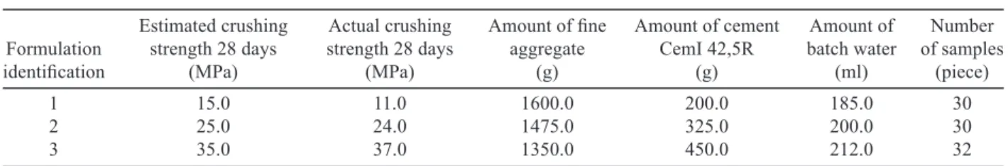
The effect of coating the surface of mortar or concrete with waterborne epoxy dispersions on the permeability for the aggressive CO2 [15] was tested on standard mortar beams with dimensions of 40×40×160 mm, made mostly according to the three basic formulations labeled 1, 2 and 3 - see Table 1.
After stripping off, the mortar beams according to the formulations 1, 2 and 3 were placed under water for 28 days, and then their moisture content was modiied to approximately 1% of moisture by gradual drying out in the laboratory. The following four combinations of waterborne dispersions including hardeners were applied separately to a selected number of standard mortar beams according to the formulations 1, 2 and 3 [3, 15]:
a) coating A - 2 layers of dispersion CHS Epoxy 200 V 55 + hardener Telalit 180,
b) coating B - 2 layers of dispersion DOW XZ 92533 + + hardener XZ 92441.01,
c) coating C - 1 layer of dispersion CHS Epoxy 200 V 55 + hardener Telalit 180 and 1 layer of dispersion Epostyl 217 V,
The Epostyl 217 coating system is a two-component system based on the dispersion CHS Epoxy 160 V 55 (waterborne solvent-free solid epoxy dispersion) and a hardener. The mixing ratio is 1 : 1.
DOW XZ 92 533 is a waterborne epoxy disper- sion from DOW Chemicals Ltd. Its viscosity (23°C) is 0.497 Pa.s according to ČSN 64 0349. The content of non-volatile matters (2h/130°C) is 46.7% wt. in accor-dance with ČSN EN ISO 3251. It is suitable to use the hardener XZ 92 441.01 from DOW. The recommended mixing ratio of DOW XZ 92 533 : XZ 92 441.01 is 100 pbw. : 20 pbw.
The selected sets of samples (some surface treated with a dispersion coating and some not) were placed in a slightly pressurized (approx. 20 mm water column) tank with a concentration of 98% CO2 for the purpose of accelerating the carbonation test - see Figure 1. The remaining samples without surface treatment were left in the natural environment of the laboratory (0.03% CO2) as reference samples.
The method for the determination of resistance of concrete treated with waterborne epoxy emulsion coatings to the effects of aggressive CO2 is based on a comparison of carbonation depths of the treated (see Figure 2) and untreated samples placed in an aggressive environment of 98% CO2. In the surface untreated samples, the carbonation depth from the accelerated test can be moreover compared to the depth of natural carbonation in the laboratory environment with approx. 0.03% CO2. What seems to be a great problem is the determination of a real acceleration of the test in 98% CO2 compared to the natural atmosphere. Here it is necessary to start with the essence of the so-called “accelerated test” described shortly in the following paragraph and in more detail in the publication [16] by the author.
According to ČSN EN 13 295, it is possible to determine the resistance of repair products or systems to carbonation by means of an accelerated laboratory test, in which the test pieces are exposed to an atmosphere containing 1% CO2 for a period of 56 days. This standard test serves in fact as a sort of initial elimination criterion for the selection of optimum repair mortars or concretes for application to the restored structure. However, it does not say much about the actual depth or extent of damage caused to the structure by carbonation in the middle or at the end of its lifetime. When deriving the correlation dependence of accelerated time / natural time, it was necessary to compare the real carbonation
depth of concretes exposed to the long-lasting effects of the natural atmosphere with the carbonation depth of comparative concretes in an environment of 98% CO2. A transition from the standard 1% CO2 to the 98% CO2 was called for by accelerating the chemical process of carbonation and by the inancial expensiveness of obtaining 1% CO2 (from Belgium). A problem of the correlation serched here will always be the absence of real pairs of the originally identical concrete samples for the determination of carbonation depth, one of which was (or is) exposed to decades of slow effects of carbonation in the structure and the other one of which undergoes a comparative accelerated test in 98% CO2.
Figure 2. 12th month of placement in 98% CO
2, coating A, B, C
and D for formulations 1, 2 and 3, average carbonation depths under the coating A: 1, 3, 0 mm, B: 20, 5, 1 mm, C: 2, 1, 2 mm and D: 15, 15, 0 mm.
Figure 1. Complete pressurized tank with an atmoshere of 98% CO2.
Table 1. Mortar mixture formulations for making standard beams 40×40×160 mm.
Estimated crushing Actual crushing Amount of ine Amount of cement Amount of Number Formulation strength 28 days strength 28 days aggregate CemI 42,5R batch water of samples
identiication (MPa) (MPa) (g) (g) (ml) (piece)
1 15.0 11.0 1600.0 200.0 185.0 30
2 25.0 24.0 1475.0 325.0 200.0 30
Carbonation depth of common concrete placed in the natural atmosphere (0.03% CO2) for a long time can be determined by calculation according to many authors (e.g. Henning, Lach [10], Matoušek, Drochytka [4], Seng Diep [11], Houst, Wittmann [17]). The relation according to [10] seems to be the most general one, the so-called Fick’s law in the following form
x = k·√t (3) which is based on the principle of a constant increase of carbonation depth with time. X indicates the depth of the carbonated layer in mm, t is the time in days and k is the constant ranging from 0.2 to 0.4 (depending on the cement type and the water ratio v/c). It is apparent that the carbonation depth will be, according to the measurements carried out on the standard samples, partially dependent on the quality of concrete. It is also interesting that the increase of carbonation depth calculated according to the Fick’s law [10] is roughly corresponding to the carbonation depths found out in poor quality concretes in the course of the one-year measurement. Figure 3
shows a conventional curve of the increase of carbonation depth derived theoretically from the Fick’s law on the one hand and from the one-year practical measurement in an environment of 0.03% CO2 on the other hand, and simultaneously a growth curve for average concrete (30 MPa in compression) determined by measurement in an environment of 98% CO2.
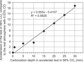
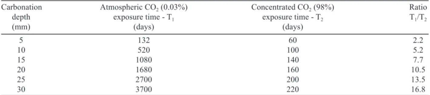
It is apparent from the chart in Figure 4 and from the following Table 2 that the speed of carbonation in an environment of concentrated 98% CO2 constantly increases in comparison with the natural environment containing 0.03% CO2. If the carbonation depth mea-sured in the tested concrete in the accelerated test after two months of placement in 98% CO2 is 10 mm, then the same damage in the real environment of 0.03% CO2 would occur in 312 days (10.4 months) - see Figure 4. However, the dependence between the time of corresponding damage of concretes in the concentrated and natural environments was determined for samples of common concrete with a 28-day strength of approx. 30 MPa.
RESULTS AND DISCUSSION
The real carbonation depth of both surface treated and surface untreated mortar beams was always deter-mined on both fragments of beams according to prEN 14630:2003, Paragraph 4.2. This is an indication of sound concrete by phenolphthalein (purple colouring) at pH > 9,4. The mutual comparison of carbonation depths of both the coated and uncoated samples (placed in 98% CO2 and in the natural atmosphere of the laboratory) was carried out in the following chronological order starting from the date of placement into 98% CO2: 1 month, 2 months, 4 months, 6 months and the last measurement after 12 months of placement in 98% CO2. Following is a quick evaluation of the state of carbonation of standard beams after the above mentioned time intervals.
Figure 4. Acceleration of the carbonation depth test in 98% CO2.
Figure 3. Different carbonation depths in an atmosphere of 98% CO2 and in the natural atmosphere both theoretically and
End of the 1st month of placement: All the four types of coating, A, B, C and D, protected the samples of three types of tested mortars (formulations 1, 2 and 3) placed in 98% CO2 quite reliably. Moreover, it is possible to say that in the irst month the coatings had an apparent positive effect on the regtrogressive „recovery“ of the cement mortar. During carbonation, water appears as its by-product contributing to a secondary hydration of the yet non-hydrated components of mastic cement, and that is why purple colouring can be seen all over the fracture area of the beam fractures. In the case of beams not protected by coating, positive inluence of concrete quality on preventing the diffusion of aggressive CO2 into the material is apparent.
End of the 2nd month of placement: It seems that the coatings labeled A and B protected the cement mortar in an environment of 98% CO2 better than the coatings C and D, nevertheless, in all four types of surface protection the measured carbonation depth ranged, for the time being, from 0.5 to 3 mm according to the quality of the cement mortar.
End of the 4th month of placement: After 4 weeks (120 days), the samples treated with type A, B, C and D coatings demonstrated a higher permeability for a concentrated 98% CO2, type C and D coatings, naturally, depending on the quality of the protected cement mortar.
End of the 6th month of placement: The protective effect of dispersion coatings has changed compared to the results from two months ago (4 months of placement in CO2), the low-quality cement mortar which is therefore most susceptible to carbonation is best protected by types A and C coatings.
End of the 12th month of placement: The highest degree of protection was demonstrated by type A sol-vent-based epoxy emulsion and by a combination of the solvent-based and the solvent-free one (type C) - see Figure 2.
As far as the protective properties of all four types of the tested waterborne epoxy dispersions A, B, C and D in realation to the penetration of CO2 are concerned, the one-year accelerated test (corresponding to approx. 8 years of real atmospheric effect of 0.03% CO2 on medium-quality concrete - derived from Figure 4) brought the following indings:
● The highest degree of protection of cement mortar was demonstrated by type A epoxy emulsion and by type C combination of the solvent-based and solvent-free emulsions (in both cases the irst type A impregnation coating is identical).
● Full protection of quality cement mortars was provided identically by all the tested waterborne epoxy dispersions of type A, B, C and D.
● Cement mortar of poor quality was not reliably protected for the period of 6 or more months (in fact 5 and more years - derived from Figure 4) by type B solvent-based foreign epoxy emulsion.
Nevertheless, in the carbonation depth test after 4 months of placement in a concentrated 98% CO2 (in fact 3 years!), both coatings, types B nad D, quite reliably reduced the penetration of CO2 into cement mortar. Therefore, in the case of application of types A and C coatings on poor quality concrete, the coating would have to be renewed after a max. of 8 years, in the case of types B and D coatings, after a max. of 3 years. In the case of type A, type B, type C and type D coatings on higher-quality concretes, the coating would have to be renewed with an interval of maximum eight years - see Table 3. The renewal intervals of the coatings were derived from the continuous evaluation of the progress of carbonation using the phenolphthalein test on the test beams over a period of one year.
When comparing modern solvent-free epoxy dis-persions of the D-type (Epostyl 217) tested here with nowadays standard products of the building chemistry manufacturers, it is necessary to take into account that the overwhelming majority of dispersions used is based Table 2. Comparison of carbonation times of the identical layers of concrete in the environment of a real atmosphere (0.03% CO2)
and in the highly concentrated environment of 98% CO2.
Carbonation Atmospheric CO2 (0.03%) Concentrated CO2 (98%) Ratio
depth exposure time - T1 exposure time - T2 T1/T2
(mm) (days) (days)
5 132 60 2.2
10 520 100 5.2
15 1080 140 7.7
20 1680 160 10.5
25 2700 200 13.5
30 3700 220 16.8
Table 3. Comparison of carbonation times of the identical layers of concrete in the environment of a real atmosphere (0.03% CO2) and in the highly concentrated environment of
98% CO2.
Formulation/coating A B C D
type-renewal interval (years) (years) (years) (years)
Formulation 1 8 3 8 3
Formulation 2 8 5 8 3
on the acrylic and tar-epoxy compositions. For example the Fosroc Limited company developed anti-carbonation paints of the elastomeric acrylic and acrylic-silane types. Two Czech companies, Spolek pro chemickou a hutní výrobu Ústí nad Labem and Panbex, produce a watertight tar-epoxy two-component compound. The disadvantage of these systems is their low vapour permeability and the resulting risk of damage to both the paint and the surface layer of concrete in the spring months. At the Conference on Coating Compositions held in Pardubice, Czech Republic, in May 2000 [18], the development of a new two-component dispersion coating was presented, which became the subject of the applied research presented here. A similar coating was developed also by the chemical concern DOW Chemicals Ltd. (DOW XZ 92 533). This substance was not subjected to the test of protection against concrete carbonation by the manufacturer, but it was used as a reference in this research.
CONCLUSIONS
The results supplement a general picture of the quality and usefulness of surface protection of mortars and concretes against diffusion of atmospheric CO2. Figure 2 is a synoptic evaluation of the quality of protection of cement mortar beams of 3 formulations by four types of coating compositions A, B, C and D. The samples were placed for 12 months in an environment of concentrated 98% CO2. It is apparent that mortars and concretes of poorer quality (low strength, low compaction, excess of gauging water) will be more susceptible to carbonation, and that protective coatings should mainly be applied to these types of concretes. Better quality concretes are resistant to the diffusion of gaseous CO2 themselves to a certain extent (lower absorption capacity, porosity). A comparison of carbonation depths in both coated and uncoated samples of the best formulation (Formulation 3 - compression strength 37 MPa) demonstrates however that surface coating with waterborne epoxy dispersions prevents even a minimum penetration of gaseous CO2 into high-quality cement mortars, and its purpose is therefore not purely preventive. A big advantage of dispersion coatings is moreover the possibility of their application on wet surfaces even at relatively low temperatures.
Further increase of effectiveness of coating systems in view of the permeability of acid gases can be achieved by an appropriate choice of aggregates with a barrier effect, and this is where further research should be performed. It would also be beneicial to pay attention to the physical properties and mechanisms of composite action of the coating and various concrete surfaces to eliminate the traditional defects of the coating systems, e.g. poor permeability and the resulting damage to the coating-protected surface of the concrete structure due to the excess pressure of water vapour.
Acknowledgement
This work was supported by Research Project of the Ministry of Education and Youth of the Czech Republic No. VVZ MSM 0021630511 „Progressive Building Materials with Utilization of Secondary Raw Materials and their Impact on Structures Durability“ and of the Ministry of Industry and Trade of the Czech Republic No. MPO ČR. FT-TA3/056 „Waterborne epoxy dispersion of new generation“.
References
1. Šmerda Z. et al.: Life of concrete structures, 1st ed.,
p.89-170, ČKAIT, Praha 1999.
2. Schulze W., Tischer W., Ettel W., Lach V.: Non-cement mortars and concretes, 1st ed., p.237-255, SNTL, Praha
1990.
3. Sebők T.: Additives and admixtures to mortars and con-cretes, 1st ed., p.133-139, SNTL, Praha 1985.
4. Matoušek M., Drochytka R.: Atmospheric corrosion of concrete, 1st ed., p.10-75, IKAS+ČKAIT, Praha 1998.
5. Kovarčík I., Vávra Z.: Costruction & Interior, 15 (2009). 6. Lőffelmannová I., Široká P.: Costruction & Interior, 22
(2003).
7. Bob C., Afana E. in: On-site assesment of concrete carbonation, Proc. Inter. Confer. Failure of Concrete Structures, p. 84-87, Štrbské Pleso, Slovak Republic 1993 8. Dhir R.K., Hewlett P.C., Chan Y.N.: Mag. Concr. Res. 148,
137 (1989).
9. Jungermann V.B.: Betonwerk Fertigteil Technik 6, 358 (1982).
10. Henning O., Lach V.: Chemistry in building industry, 1st ed., p.63-69, SNTL, Praha 1983.
11. Diep S., Šlopková K.: Inluence of concrete carbonation on the corrosion of ferroconcrete elements, 1 st ed., p.36-56, TU Žilina, Žilina 2000.
12. Pytlík P.: Concrete technology, 2nd ed., p.304-310 a
366-371, VUTIUM, Brno 2000.
13. Šauman Z.: Introduction to general physical chemistry and fundamentals of physical chemistry of silicates, 1st ed.,
p.140-159, SNTL, Praha 1965.
14. Vavřín F., Retzl K.: Protection of building structures from corrosion, 1st ed., p.11-130, SNTL, Praha 1987.
15. Pichrt A.: Chemical revue, 10 (1986).
16. Stehlík M. in: Principle of the accelerated carbonation depth test in 98% CO2, p.115-117, Ed. Kořenská M.,
Pazdera L., Academic Press Cerm s.r.o., Brno 2008. 17. Houst Y.F., Wittmann F.H.: Depth proiles of carbonates
formed during natural carbonation, Cem. Concr. Res. 32, 1923-1930 (2002).