_____________________________
*) Corresponding author: zhyab@126.com
doi: 10.2298/SOS1002203Z
UDK 622.785:549.613.4
Characterization of Defects of Mullite Fibers Prepared by
Polyvinyl Butyral as Spinning Aid
Y.b. Zhang
1,*),
C.F. Xiao
1, S.L. An
1, J.F. Yang
2, S.J. Xu
31)
Key Laboratory of Hollow Fiber Membrane Material and Membrane Process of
Ministry of Education, Tianjin Polytechnic University, Tianjin 300160, People’s
Republic of China
2)
State Key Laboratory for Mechanical Behavior of Materials, Xi’an Jiaotong
University. Xi’an 710049, People’s Republic of China
3)
Department of Solar Energy Science and Engineering, Xinyu College, Xinyu
338000, People’s Republic of China
Abstract:
Mullite fibers have been synthesized using polyvinyl butyral as spinning aids. Defects including cracks, core-sheath structure, randomly arranged powders, shots and rough surface were observed. The results showed that circumferential cracks were terminated by the main axial crack. The thermal shrinkage could be considered as the reason for the formation of cracks and core-sheath structure. Improper control of heat treatment resulted in the rough surface around fibers. The wet gel fibers were easily inserted by some alumina powders which were used to obtain the uniform shrinkage during calcinations in the kiln.
Keywords: Mullite fiber; Sol-gel processes; Sintering; Microstructure; Thermal expansion.
Introduction
Mullite fibers have various outstanding properties including good mechanical strength at high temperature, creep resistance, thermal and chemical stability in oxidization or reduction atmospheres, low thermal expansion coefficient, low thermal conductivity and so on [1-5]. As one of the most prominent high strength materials, mullite fiber has been widely used as reinforcement of metals, ceramics and resins. In addition, the unusual thermal and dielectric properties of mullite fibers suggest many important applications of high temperature materials in the forms of mats, blankets, boards, etc.
expensive that this method is not suitable for the preparation of mullite fiber widely. Spinning aids-based approach has been a trend for preparing mulllite fiber in recent decade [17, 18], because spinning aids are cheap and easy to obtain. The addition of spinning aids into the solution can provide or improve the spinnability and rheological property according to many recent researches [19, 20]. Spinning sol is formed when the polymer aids-based solution is aged or condensed. Subsequently, mullite fibers can be obtained through further drying and calcinations.
Many factors have important influence on the surface morphology and the formation of various kinds of defects in mullite fibers. The defects, which are formed during fabrication of mullite fibers, have been studied by many researchers. However, little research on further analysis of fiber defects, such as the propagation of cracks and core-sheath structure, has been reported.
In this paper, the composite gel fibers were drawn from spinning sol which was prepared using TEOS, aluminum nitride (Al(NO3)3·9H2O, AN) and commercial grade
polyvinyl butyral (PVB). The fibers surface morphology was characterized and further research on the propagation of fiber cracks was also studied in detail.
2. Experimental
Starting materials used in this experiment were AN (Chemical grade, Xi’an Reagent Factory, Xi’an, China) and TEOS (Chemical grade, Xi’an Reagent Factory, Xi’an, China), which were employed as Al source and Si source respectively. PVB (SD-1, Tianjin Huida Chemical Industry Co., Ltd, Tianjin, China) was selected as spinning aids, and ethanol (Chemical grade, Xi’an Reagent Factory, Xi’an, China) was used as solvent.
Aluminosilicate sol with stoichiometric mullite composition was prepared as follows. First of all, AN was dissolved into ethanol at room temperature under vigorously stirring and an aqueous solution with molar concentration of 2M was obtained. TEOS was measured according to stoichiometric mullite composition, and mixed with the AN-ethanol solution. The uniform mixture solution was obtained through further vigorously stirring at room temperature. As a spinning aid, PVB was added slowly into the mixture solution. The solution was stirred vigorously at room temperature until PVB was dissolved completely. The weight ratio of [AN]/[PVB] in the mixture solution was five, which corresponded to the weight ratio [3Al2O3·2SiO2]/[PVB] of 1.13. Then, sol fibers were drawn quickly at room temperature by a
hand drawing method. Subsequently, the gel fibers were dried at 40oC. The dried gel fibers were then calcined at 1200oC with a heating rate of 10oC /min. During the calcination process, the gel fibers were covered up with alumina powders, which had been calcined at 1000oC beforehand, and the aim was to obtain the uniform shrinkage around the fibers.
The fibers were then gold-coated using sputter coating under vacuum and they were subsequently characterized at various magnifications using scanning electron microscope (SEM), which was carried out on JSM-35C instrument (JEOL, Tokyo, Japan).
3. Results and discussion
In the different heat treating condition, some superficial defects, such as cracks, shots, core-sheath structure, rough surface and randomly arranged powders, were shown on the fiber surface.
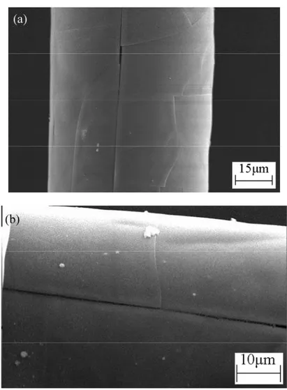
occasion, multiple short cracks were also introduced to the fiber surface. They were almost parallel to the main axial crack and developed in various locations between circumferential cracks.
Fig. 1 Cracks paralleled or vertical to the fiber axis
SEM observation of fiber surface revealed the details regarding the cracks propagation behavior. Obviously some crack termination was shown at the fiber surface according to the SEM results. It was clear that almost all the circumferential cracks were held back when they propagated to the main axial crack and it could be concluded that the formation of axial crack was prior to the presence of circumferential cracks. Furthermore, the short cracks paralleled to the main axial cracks were also terminated by the circumferential cracks.
On the contrary, fiber exhibited well distributed solvent content along the fiber axial direction compared with the fiber radial orientation. As a result, there was regular thermal expansion coefficient, and the unchanging in the thermal expansion coefficient resulted in the absence of heat stress. In consequence, it was reasonable to consider the slowness of the circumferential cracks formation in comparison to the axial crack because of the obvious difference of radial heat stress. This could also explain the SEM result that circumferential cracks were held back by a main axial crack as shown in Fig.2 (b). SEM results also revealed that the circumferential cracks were accompanied by some small axial cracks. This result indicated that the small axial cracks were present at the same time of formation of circumferential cracks, and they were terminated by the circumferential cracks as shown in Fig.2 (c). The schematic view of crack formation was shown in Fig.2
Fig. 2 Schematic view of crack propagation due to the heat stress
The calcined fibers also exhibited groove-like features which could be seen on SEM micrograph as shown in Fig.3. The grooves had a diameter of about 1μm and a length of 10-20μm, and they were parallel or vertical to the fiber axis. Furthermore, the two kinds of slot-like features paralleled or vertical to the fiber axis were formed simultaneously. This surface morphology was the indication of formation of circumferential cracks and small axial cracks, which could be attributed to the removal of organic materials and microstructure densification as mentioned above.
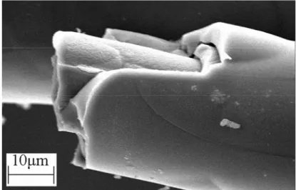
The heat stress introduced during the fiber fabrication had effect not only on the development of surface crack but also on the formation of core-sheath structure on the cross-section of mullite fiber. As shown in Fig.4, core-sheath structure, which was accompanied by axial cracks, was observed on the fracture morphology of calcined fiber. The schematic view of the formation of core-sheath structure was shown in Fig.5. The fiber structure depended on the structure of spinning sol, drying and calcinations processes mainly. Homogeneous spinning sol could be obtained through further stirring as shown in Fig.5 (a). So core-sheath structure could mainly be caused by improper control over removal of solvent and organic during drying and calcinations stages [23]. At improper drying rate, gel fibers with moisture gradient from the core to the surface were easily obtained, and it led to the outer dense sheath and inner loose core in the gel fibers, as shown in Fig.5 (b). During the calcinations stage, the solvent concentration was higher in the core section than it in the fiber outer sheath. So the shrinkage of the fiber center was more notable [24] in comparison to the fiber surface. As a result, the core-sheath structure was formed as shown in Fig.5 (c).
Fig. 4 Core-sheath structure due to the high heating rate
Fig.5 Schematic view of the formation of core-sheath structure
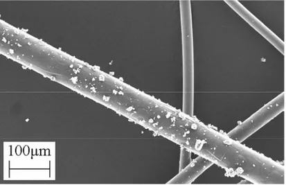
exhibited numerous particles at the size around 1-10μm. These particles stuck into the surface of fiber and appeared rough. It was obvious that these particles observed on the fiber exterior could not be recognized as a part of fibers. The rough surface observed through SEM indicated the high humidity of fiber before the calcinations of gel fibers. As a result, the wet gel fibers were inserted by the alumina powders which were used to get the uniform shrinkage of gel fibers in the kiln. The coarse topographic morphology was kept during calcinations, which accompanied by evolution of dense material.
Fig. 6 Wet gel fibers were stuck by some alumina powders and the structure was kept after calcinations
The mullite fibers were collected after they were calcined at 1200oC. The presence of shot was observed as shown in Fig.7. Venkatesh et al. [21, 25] have given a reasonable explanation for the formation of surface shots. They considered that the variation of surface tension led to the instability of spinning and caused shot to form during the spinning procedure. This could be considered to be the reason which resulted in the fiber product with poor quality [26].
Fig. 7 Shot due to the improper surface tension and spinning condition
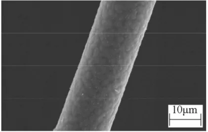
control of heating scheme, including the calcinations temperature, heating rate and holding time. High calcinations temperature, low heating rate or long holding time could lead to the fact that fibers were exposed to higher temperature for a long time, which accelerated the phase transformation and grain growth of the fine diameter grain [21, 27]. The effect was more significant for the preparation of fibers by sol-gel method. So the calcinations scheme must be well controlled to obtain the high quality fibers.
Fig. 8 Fiber surface with many crystals due to the long holding time
5. Conclusions
Various defects of mullite fibers, which were prepared using spinning sol with polyvinyl butyral as spinning aids, have been observed. Defects that could occur during fiber heat treatment included cracks, core-sheath structure, randomly arranged powders, shots and rough surface. The formation of main axial crack took place due to the different thermal expansion along the radial direction. The circumferential cracks were developed and terminated by the main axial cracks. The presence of core-sheath structure was attributed to the different shrinkage between fiber center and fiber surface during the heating treatment. Because of the low hardness, the wet gel fibers were inserted by some alumina powders which were used to obtain the uniform shrinkage during calcinations in the kiln.
Acknowledgments
This work was supported by the National Natural Science Foundation of China (No. 50772086, 50821140308), and the High-Tech R & D Program of China (863, No. 2007AA03Z558), and by Research Fund for the Doctoral Program of Higher Education under contract NO. 20060698008.
References
1. W. Li, H. Y. Fan, X. J. Zhang, B. L. Shen, S. J. Gao, M. J. Tu, C. Li, S. Y. Qiu, J. Mater. Sci., 39 (2004) 1875.
3. K. K. Chawla, J. Eur. Ceram. Soc., 28 (2008) 447.
4. A. R. Boccaccini, S. Atiq, D. N. Boccaccini, I. Dlouhy, C. Kaya, Compos. Sci. Technol., 65 (2005) 325.
5. C. Kaya, E. G. Butler, A. Selcuk, A. R. Boccaccini, M. H. Lewis, J. Eur. Ceram. Soc., 22 (2002) 2333.
6. A. R. Bunsell, M. H. Berger, J. Eur. Ceram. Soc., 20 (2000) 2249. 7. W. Pan, R. T. Li, Mater. Sci. Eng. A, 271 (1999) 298.
8. Z. J. Xiao, B. S. Mitchell, Mater. Lett., 37 (1998) 359.
9. C. H. Ruscher, S. T. Mileiko, H. Schneider, J. Eur. Ceram. Soc., 23 (2003) 3113. 10. S. T. Mileiko, A. V. Serebryakov, V. M. Kiiko, A. A. Kolchin, V. N. Kurlov, N. I.
Novokhatskaya, J. Eur. Ceram. Soc., 29 (2009) 337.
11. W. Yoon, P. Sarin, W. M. Kriven, J. Eur. Ceram. Soc., 28 (2008) 455. 12. K. C. Song, Mater. Lett., 35 (1998) 290.
13. X. T. Chen, L. X. Gu, J. Sol-Gel Sci. Technol., 46 (2008) 23.
14. J. Chandradass, M. Balasubramanian, J. Eur. Ceram. Soc., 26 (2006) 2611.
15. Y. Gotoh, K. Fujimura, Y. Ohkoshi, M. Nagura, K. Akamatsu, S. Deki, Mater. Chem. Phys., 83 (2004) 54.
16. K. Okada, S. Yasohama, S. Hayashi, A. Yasumori, J. Eur. Ceram. Soc., 18 (1998) 1879.
17. Y. B. Zhang, Y. P. Ding, J. Q. Gao, J. F. Yang, J. Eur. Ceram. Soc., 29 (2009) 1101. 18. C. B. Jing, X. G. Xu, J. X. Hou, J. Sol-Gel Sci. Technol., 45 (2008) 109.
19. J. Chandradass, M. Balasubramanian, J. Mater. Process. Technol., 173 (2006) 275. 20. Y. B. Zhang, Y. P. Ding, Y. Li, J. Q. Gao, J. F. Yang, J. Sol-Gel Sci. Technol., 49
(2009) 385.
21. R. Venkatesh, S. R. Ramanan, Mater. Lett., 55 (2002) 189.
22. H. Miyazaki, Y. Yoshizawa, K. Hirao, Mater. Lett., 58 (2004) 1410.
23. M. Peng, Q. J. Sun, Q. L. Ma, P. Li, Microporous Mesoporous Mater., 115 (2008) 562.
24. R. Venkatesh, Compos. Sci. Technol., 62 (2002) 205.
25. R. Venkatesh, S. R. Ramanan, J. Eur. Ceram. Soc., 20 (2000) 2543.
26. R. C. Pullar, M. D. Taylor, A. K. Bhattacharya, J. Eur. Ceram. Soc., 22 (2002) 2039. 27. J. M. Heintz, J. C. Bihr, J. F. Silvain, J. Eur. Ceram. Soc., 19 (1999) 1759.
Са р а:
. ,
- , ђ .
. Т
-.
. В
.
К учн р чи: , - , , ,