A R C H I V E S
o f
F O U N D R Y E N G I N E E R I N G
Published quarterly as the organ of the Foundry Commission of the Polish Academy of Sciences
ISSN (1897-3310)
Volume 10
Issue 3/2010
149 – 154
29/3
Semi-solid processing method for cast iron
W. Wierzchowski
*,
T. Grochal
Foundry Research Institute, 30-418 Kraków, ul. Zakopia
ń
ska 73, Poland
Corresponding author. E-mail adress: [email protected]
Received 30.04.2010; accepted in revised form 01.07.2010
Abstract
A device for the fabrication of ingots from cast iron of globular non-dendritic structure of the primary phase was designed and made, using the principle of overflow on the Slope Cooling Plate, known as the SCP method. Trials were made on hypoeutectic grey cast iron and high-chromium cast iron. Even during the first trials the intended effect has been achieved, which means that a fragmentation and globularization of the primary austenite was obtained. A simultaneous effect of the applied SCP technique on the shape of graphite in grey cast iron was observed.
Keywords:cast iron; semi-solid processing, thixocasting, globular structure of iron alloys
1. Introduction
The methods of external influence on metal alloys in semi-solid state, i.e. when the temperature of the alloy is between the liquidus temperature TL and solidus temperature TE, are commonly called semi-solid techniques or semi-solid processing. In practice it refers to hypoeutectic alloys, and the essence of the technique consists in preventing the dendritic crystallization of a primary phase. In this way, the conditions are created to achieve special rheological characteristics, possibly also a thixotropic effect [1, 2]. In castings made by semi-solid techniques, the fragmentation and globularization of primary precipitates takes place and the size of the eutectic phase components is reduced. Materials characterized by these properties offer the following advantages: maximum homogenization of the structure and maximum decrease of shrinkage, both of which enable the “near-net-shape” (“net-to-shape”) fabrication. In the case of aluminum and magnesium alloys, the semi-solid techniques have been in use since the 80-ties of the last century and they are becoming more and more common. This situation creates new scientific and technological opportunities, e.g. the development of new alloys becomes possible. Besides, if suitable treatment (e.g. heat treatment) is additionally carried out, the result can be extraordinary mechanical properties [7].
the thixo-structured alloys and on the semi-solid (SSM) processing. However, the only alloys with this structure put into practice so far have been aluminum and magnesium alloys. Semi-solid slurries for industry are prepared by mechanical, electromagnetic (MHD-magnetohydrodynamic) and ultrasonic stirring.
There are numerous industrial techniques for forming of objects with thixotropic structure. They can be divided into two groups: rheoforming and thixoforming. If an object is formed from the liquid slurry directly after preparing the latter, the process is called rheoforming and it has two variations, viz. rheocasting (usually pressure die casting) and rheoforging (die forging). Continuous casting of metal passing through a concast nozzle in the unit with MHD effect (production of bars and sections) is an important type of rheocasting. If an object is formed from the previously prepared (by cutting off) ingot with globular structure after heating the stock to semi-solid state, the process is called thixoforming.
Thixoforming also falls into two discrete processes: thixocasting and thixoforging. There is a technology in which both types are mixed. Raw materials for thixoforming are usually prepared by continuous casting with mechanical or electromagnetic stirring.
The studies on semi-solid processing of high-melting alloys, including cast iron, are less advanced. It is necessary to emphasize the fact that until now there has been no information about any industrial application of this technique. The reason for such situation is the difficulty in preparing cast iron with globular microstructure and problems related with a technology which could serve for forming alloys of this type [8]. However, a growing interest of engineers and scientists in this technique has been observed recently. A lot of papers on this subject appeared at the close of the 90-ties of the last century and in the few past years [4–10], of which a significant part comes from the Japanese research centers and universities. These publications underline the great importance of possible application of the semi-solid processing of iron alloys, particularly of the cast iron. They claim that economical and technical advantages will be the same or nearly the same as in the case of low-melting alloys. Some of them forecast e.g. possible increase of the tensile strength by even 20% [7].
The hope for introducing into practice the semi-solid processing of cast iron and alternatively of other high-melting alloys is now becoming more and more possible, and this is due to a new method of thixotropic structure preparation. The new method mainly consists in overflowing the liquid alloy over the slope cooling metal plate surface [7–10], and hence it is different from the previous processes based on stirring. Depending on requirements, the initial temperature of the alloy should be slightly higher than the point of liquidus TL, while final temperature should be in the range of liquidus-solidus temperatures (TL to TE ).
The new method is commonly called SCP method (abbrev. from – Slope Cooling Plate). According to A. Ohno [after 8], the mechanics of the slurry formation by SCP method is due to sudden increase in the number of the crystal nuclei of the primary phase during alloy overflowing on SCP, due to which the conditions proper for a dendritic growth of the primary phase disappear under the effect of liquid metal free motion. A suitable
liquid metal cooling rate is an indispensable condition, too, and therefore the SCP plates are made of copper and usually are provided with a water cooling system. The type of SCP coating applied on the way of the liquid metal stream flow has been an important technological problem: it should be a good heat conductor and iron non-wettable. This problem was solved by application of coatings based on the hexagonal boron nitride. This material offers the lubricating ability similar to graphite coatings – it is insoluble in iron and resistant to the liquid iron temperature while flowing on SCP. Thus, the SCP method presents itself as a simple one and according to the above mentioned papers it produces thixotropic iron with greater homogeneity and dispersion of the primary phase precipitates than the degree that can be obtained in the cast iron prepared by stirring.
2. Experimental
Fig. 1. Schematic image of the SCP unit
The schematic image of a SCP unit, which has been built by the authors basing on the published information [7–10], is presented in Fig. 1. The unit, further called a SCP crystallizer, was equipped with the following elements: plate slope control mechanism, water cooler, pouring system with continuous temperature measurement of liquid metal and temperature measurement at the end of the plate. In the first version, the plate slope control mechanism made it possible to control the slope angle in the range of 0–15° (the range larger by about 5–8° than that stated in the literature). The copper plate, first with dimensions of 600 x 197 x 38 mm, is a fundamental element of the crystallizer. The U-groove for metal overflowing is milled along the top surface of the plate. The surface of the metal flow was covered by spraying with ZYT BN Lubricoat ZC coating (hexagonal BN in the form of water suspension).
At first [13], the following four grades of the cast iron were tested: carbon hypoeutectic iron with lamellar graphite, typical nodular and vermicular graphite irons, and high-chromium iron. The pouring temperature was calculated according to the
following formula: TP = TL + 20 K, for which the critical values
of liquidus TL and solidus TE were determined by thermal
homogeneous austenite grains surrounded by eutectic, were obtained, but only in the case of hypoeutectic and high-chromium irons.
Unfortunately, free metal flow and satisfactory mold filling were observed only when the slope angle was at its maximum, that is 15°.
Table 1.
Data of the investigated irons with lamellar graphite Elements content, % Sample
designation C Si Mn
The range temperature: liquidus
TL; solidus TE,
°C
Overheating, K Cast temperature,
°C
01 Sz 3,15 2,07 0,47 1189 ; 1149 80 1270
02 Sz 3,10 2,06 0,46 1199 ; 1147 60 1260
11 Sz 3,05 2,08 0,46 1207 ; 1147 90 1297
12 Sz 2,90 2,03 0,45 1210 ; 1146 110 1320
21 Sz 2,80 2,02 0,44 1238 ; 1144 100 1338
22 Sz 2,70 2,06 0,44 1255 ; 1141 115 1370
Table 2.
Data of the investigated high-chromium irons Elements content, % Sample
designation C Mn Cr
The range temperature:
liquidus TL; solidus TE,
°C
Overheating, K Cast temperature,
°C
01 C 2,80 0,57 12,60 1275 ; 1216 50 1325
02 C 2,70 0,53 12,70 1281 ; 1219 70 1350
11 C 2,65 0,52 12,70 1281 ; 1222 60 1244
12 C 2,70 0,56 12,70 1286 ; 1222 80 1366
21 C 2,60 0,50 12,75 1290 ; 1222 70 1360
22 C 2,60 0,48 12,75 1288 ; 1223 90 1378
Tests confirmed the published information about the potentials offered by the SCP method, but at the same time they proved that some of the values quoted in the papers are far from the boundary conditions. That is why we decided to redesign the SCP unit. The copper plate (potential flow way) was lengthened to 1000 mm (+400 mm) and the mechanism of slope control was changed to enable the slope angle to be adjusted to ma-ximum 25°. The metal pouring method was also changed to improve the flow way control and enable metal stream
stabilization.
After modification of the SCP unit, the second series of tests was made [14]. The tests included two cast iron grades, i.e. hypoeutectic iron with lamellar graphite and high-chromium iron. Both of them were tested at three lengths of the metal stream way. The data concerning these irons are compiled with breakdown into iron grades in Tables 1 and 2. The chemical analysis was made on a HILGER POLYVAC spectrometer type E 983. The content of the most important elements (C, Si, Mn in gray iron and C, Mn Cr in high-chromium iron) was included in the tables only because the content of the residual elements was contained in a very narrow range of values and on the proper level. The pouring temperature was determined in a special way, using as a starting point the beginning of metal freezing on the melt surface in a ladle; consequently, two different temperatures were applied for each length of the stream flow way, and so, each grade of the cast iron was poured 6 times (3 lengths × 2 temperatures). Sample designation of gray iron had two numbers and the symbol “Sz”; in the case of high-chromium iron, similar numbers and the symbol “C” were used. The first
number in the designation (0, 1 or 2) determines the flow stream length, while the second number (1 or 2) is connected with temperature. In the numbers describing the flow stream length, “0” stands for 600 mm length, “1” for 800 mm length, and “2” for 1000 mm length. All tests in the second series were made with maximum slope plate angle of 25°. Tests with smaller angle were given up because of mold filling problems.
3. Results
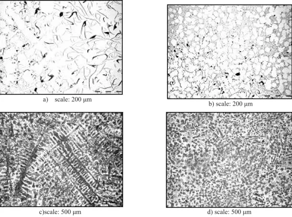
As mentioned above, the metallographic examinations were the basis for the investigation of the effectiveness of a semi-solid SCP process. The task was realized by comparing the microstructure of cast iron poured into the mold after melting (before SCP treatment) with microstructure of the same cast iron but after SCP treatment. The primary phase precipitates morphology was examined in samples prepared for the examinations by selective etching, depending on the cast iron grade. In the case of gray iron it was hot etching with a reagent made according to [11]; in the case of high-chromium iron etching was done with a LBI reagent made according to [12]. Additionally, the graphite morphology was examined on the polished samples made from gray iron. The examples of microstructures are shown in Figs. 2–5, and the results of graphite estimation basing on PN-EN ISO 945 Standard are shown in Table 3.
results obtained for the shortest (600 mm) and longest (1000 mm) metal stream flow way (compare Fig. 2 with Fig. 3, and
Fig. 4 with Fig. 5). All these examples prove that samples cut out from
a) scale: 200 μm
b) scale: 200 μm
c)scale: 500 μm d) scale: 500 μm
Fig. 2. Specimen 02 Sz (metal stream length 600 mm; ΔT = 60 K):
a) graphite microstructure after melting; b) graphite microstructure after SCP treatment; c) matrix microstructure after melting; d) matrix microstructure after SCP
a) scale: 500 μm b) scale: 500 μm
Fig. 3. Specimen 22 C (metal stream length 1000 mm; ΔT = 90 K):
a) scale: 500 μm b) scale: 500 μm
Fig. 4. Specimen 02 C (metal stream length 600 mm; ΔT = 70 K):
a) microstructure after melting; b) microstructure after SCP treatment. Both after etching by LBI
a) scale: 200 μm b) scale: 200 μm
c) scale: 500 μm d) scale: 500 μm
Fig. 5. Specimen 21 Sz (metal stream length 1000 mm; ΔT = 100 K):
a) graphite microstructure after melting; b) graphite microstructure after SCP treatment; c) matrix microstructure after melting; d) matrix microstructure after SCP treatment
castings poured from metals processed in the SCP process are characterized by globular form of the structure of a primary phase and/or by the granular structure considerably refined. The samples cut out from castings poured directly after melting of these metals have a dendritic structure of the primary phase. The results of the examinations of the remaining samples are similar.
The unquestionable and distinct influence of the SCP pro-cess on the shape, size and distribution of graphite precipitates was established in all cases of the investigations made on the samples
Table 3.
Graphite morphology Sample
designation Specimen metal state
Graphite microstructure according to: PN-EN ISO 945
After melting IA4 – 100%
01 Sz
After SCP treatment ID6 – 30%; ID8 – 70%
After melting IA4 – 50%; ID5 – 50%
02 Sz
After SCP treatment ID5 – 40%; ID8 – 60%
After melting IA4 – 30%; ID5 – 70%
11 Sz
After SCP treatment ID7 – 30%; ID8 –70%
After melting IE5 – 100%
12 Sz
After SCP treatment ID6 – 50%; ID8 – 50%
After melting ID5 – 100%
21 Sz
After SCP treatment ID6 – 100%
After melting ID5 – 100%
22 Sz
After SCP treatment ID7 – 30% ; ID8 – 70%
IA4, IA4 +ID5, ID5 and IE5 in PN-EN ISO 945 Standard, and depends on the carbon content, whereas in samples coming from the SCP treated iron it usually corresponds to symbols ID8, ID7and ID6, or in a mixed form, additionally to ID5.
4. Conclusions
The authors confirmed the published information that it is possible to develop a thixo1. tropic structure in cast iron, i.e. the structure with globular precipitates of the primary phase, by metal stream overflow on a slope cooling plate (SCP method), particularly in hypoeutectic carbon iron with lamellar graphite and in high-chromium iron; they also revealed that the published parameters of the SCP process are probably outside an optimum range.
The influence of the SCP process on the shape, size and distribution of graphite 2. precipitates in carbon hypoeutectic iron along with a globular structure of the primary phase can exert an interesting effect on the mechanical properties; the next studies should cover a larger number of the tests to examine all the material properties, particularly the mechanical ones.
The authors’ experiments, which have been carried out until now, have not yet re3. sulted in precise determination of the boundary conditions for a SCP process; to achieve this goal, the authors should continue their investigations, and then set up the optimum parameters of the process.
References
[1] Flemings M. C.: Behaviour of Metal Alloys in the Semisolid
State. Metallurgical Transactions 1. A, May 1991, vol. 22A, p. 957.
[2] Kirkwood D. H.: Semisolid metal processing. Int. Materials
Rev., 1995, vol. 39, nr 5, p. 1732.
[3] Yoneda H., Fukuda T., Ishino T.: Influence of primary
crystal morphology on the strength of low 3. carbon gray cast iron stirred in the primary solidification process. Proc. 59th WFC, Sao Paulo 1992, p. 18.3.
[4] Qiu P., Nomura H., Takita M.: Mould filling behaviour and
solidification structure of semi-solid 4. gray iron. Int. J. Cast Metals Research, 2000, vol. 13, p. 93.
[5] Muumbo A., Nomura H.: Micro-structural characterisation
and mould-filling behaviour of gray 5. cast iron stirred in the semi-solid state. Int. J. Cast Metals Research, 2002, vol. 15, p. 31.
[6] Poolthong N., Qiu P., Nomura H.: Primary particle
distribution in cast iron by semi-solid proces6. sing under centrifugal field. Int. J. Cast Metals Research, 2003, vol. 16, p. 566.
[7] Muumbo A., Nomura H., Takita M.: Mechanical properties
and microstructure of semi-solid 7. processed cast iron. Int. J. Cast Metals Research, 2003, vol. 16, nr 1-3, p. 259.
[8] Muumbo A., Nomura H., Takita M.: Casting of semi-solid
cast iron slurry using combination of 8. cooling slope and pressurisation. Int. J. Cast Metals Research, 2004, vol. 17, no. 1, p. 39.
[9] Poolthong N., Nomura H., Takita M.: Effect of heat
treatment on microstructure, wear proper9. ties and corrosion characteristics of semi-solid processed high chromium cast iron. Int. J. of Cast Metals Research, 2003, vol. 16, n° 6, p. 566.
[10] Pahlevani F., Nili-Ahmadabadi M.: Development of
semi-solid ductile cast iron. Int. J. of Cast Metals Research, 2004, vol. 17, n° 3, p.157.
[11] Tian H., Stefanescu D. M.: Application of a Coloration
Etching Method to the Study of Micro11. structures in Primary and Eutectic Solidification in Cast Iron. MATERIALS Characterisation 29.329-333 (1992), 1044-3803/92.
[12] Weck, Leistner E.: Metallographic instructions for colour
etching by immersion. Part II. Düs12. seldorf, 1983
[13] Wierzchowski W. i in.: Technika semi-solid w zastosowaniu
do żeliwa. Etap I, Prace Nauk.-13. Bad. Instytutu
Odlewnictwa, Kraków, 2005.
[14] Wierzchowski W. i in.: Technika semi-solid w zastosowaniu
do żeliwa. Etap II, Prace Nauk.-14. Bad. Instytutu