© 2016 IBRACON © 2016 IBRACON
Experimental analysis of reinforcing columns
of reinforced concrete, with anchor steel bolts
Análise experimental de reforço de pilares em
concreto armado, com chumbadores metálicos
a CMEC, UFG, SRocha Consultoria e Projetos Ltda., Goiânia, GO, Brasil;
b Universidade Federal de Uberlândia, Centro de Ciências Exatas e Tecnologia, Faculdade de Engenharia Civil; c Universidade Federal de Goiás, Faculdades de Engenharia, Regional Catalão, Catalão, GO, Brasil. Received: 22 Oct 2015 • Accepted: 06 May 2016 • Available Online: 23 Sep 2016
A. C. MESQUITA a
A. S. ROCHA a [email protected]
R. G. DELALIBERA b
W. A. DA SILVA c [email protected]
Abstract
Resumo
This article presents a columns reinforcement experimental study, with the use of anchor steel bolts and ill with self-compacting concrete. Were tested ive columns of reinforced concrete subjected to lexion-compression: two columns were used as reference, and a cross-section equal to 120 x 250 mm; with a monolithic section equal to 155 x 250 mm cross section of the same reinforced columns and three which were initially molded with a 120 x 250 mm section and subsequently received a layer of 35 mm thick self-compacting concrete in the compressed side. Despite the studs do not present break, there was peeling of the reinforcement layer. The results indicate the possibility of using this method in reinforcing structural rehabilita
-tion of reinforced concrete columns, with increase in load capacity on average equal to 403% in rela-tion to the column reference.
Keywords: columms, reinforcement, lexo-compression, reiforced concrete, anchor bolts.
Este artigo apresenta um estudo experimental de reforço de pilares, com emprego de chumbadores metálicos e preenchimento com concreto
autoadensável. Foram ensaiados cinco pilares de concreto armado submetidos à lexo-compressão: dois pilares foram usados como referência, sendo um com seção transversal igual a 120 x 250 mm; um monolítico com seção igual a 155 x 250 mm, mesma seção transversal dos pilares reforçados e três, que inicialmente foram moldados com seção de 120 x 250 mm e posteriormente receberam uma camada de 35 mm de espes
-sura de concreto autoadensável na face comprimida. Apesar dos chumbadores não apresentarem ruptura, houve o desplacamento da camada do reforço. Os resultados obtidos indicam a possibilidade da utilização deste método de reforço na reabilitação estrutural de pilares de concreto armado, apresentando acréscimo na capacidade resistente em média igual a 403 % em relação ao pilar de referência.
1. Introduction
1.1 Initial considerations
Columns are linear straight shaft elements, usually arranged vertically where the normal compressive forces are predominant, according to ABNT NBR 6118 [5]. They are intended for sharing external actions to the foundations, although may also transmit to other supporting elements, such as pillars supported transition beams. The active shares on the pil-lars are generally from the beams and slabs. The pilpil-lars are the most important structural elements in the structures, from the point of view of bearing capacity and stability of the building’s structural elements, as in
the safety aspect. According to Bastos [6], in addition to the transmission of vertical loads to the foundation elements, the pillars are part of the brac-ing system responsible for ensurbrac-ing the overall stability of the buildbrac-ing. The Federal University of Goiás (UFG), in partnership with the Uni-versity of Brasilia (UNB), has been developing lines of research on structural reinforcement and Column in reinforced concrete
initi-ated by Adorno [10] followed by Araújo [9] Omar [7] Sahb [1], Melo [12] Birth [8], Marques [3] Ferreira [4] and Virgin [2].
1.2 Reasons
The structural rehabilitation area has shown increasing importance
Table 1 – Main characteristics of the columns
Main characteristics and nomenclatures of the tested columns
Nomenclature Section (mm) Nº anchor bolts
eens
(mm)
Ø bolts. (mm)
eref
(mm)
Referência (Pref) 120 x 250 – 60 – –
Monolítico (Pmon) 155 x 250 – 42,5 – –
P6-150-34-AP150-SP (P1) 155 x 250 34 42,5 8 35
P6-150-34-AP75-SP (P2) 155 x 250 34 42,5 8 35
P6-150-34-AP75-CP (P3) 155 x 250 34 42,5 8 35
SP – Anchor bolts without ferrule; CP – Anchor bolts with ferrule; eens – Loading application eccentricity offset structure; eref – thickness of the reinforcing layer
798 IBRACON Structures and Materials Journal • 2016 • vol. 9 • nº 5
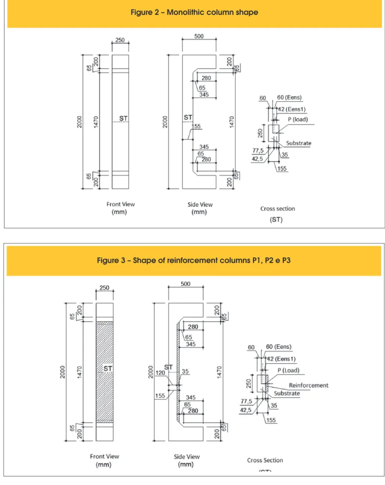
Figure 2 – Monolithic column shape
in the construction industry, taking into account the need to re
-duce work time, bolder architectures with large spans and slender
buildings, among other reasons. The need to strengthen employ-ment can be applied to structures, correcting pathological building problems or increasing their load bearing capacity. However, even with the development of this branch, the professional structural re-habilitation area still relies primarily on empirical models because
there is no speciic Brazilian standard for analysis and design of rehabilitated parts. Thus, it is intended to deepen the knowledge of structural reinforced pillars, speciically with metal studs.
1.3 Objective
The objective of this study is to analyze the behavior of reinforced pil
-lars after breaking, in order to verify the peeling of the reinforcement.
2. Experimental program, materials
and methods
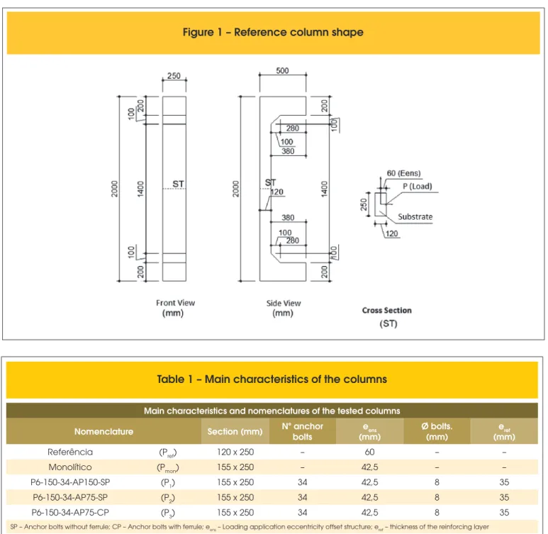
2.1 Geometrical characteristics of the columns
For this research were built ive pillars, being a reference (Pref),
with cross section of 120 x 250 mm (original section), a monolithic
(PMON) whose cross-section is the same as the reinforced pillars,
155 x 250 mm, but performed in a single molding and
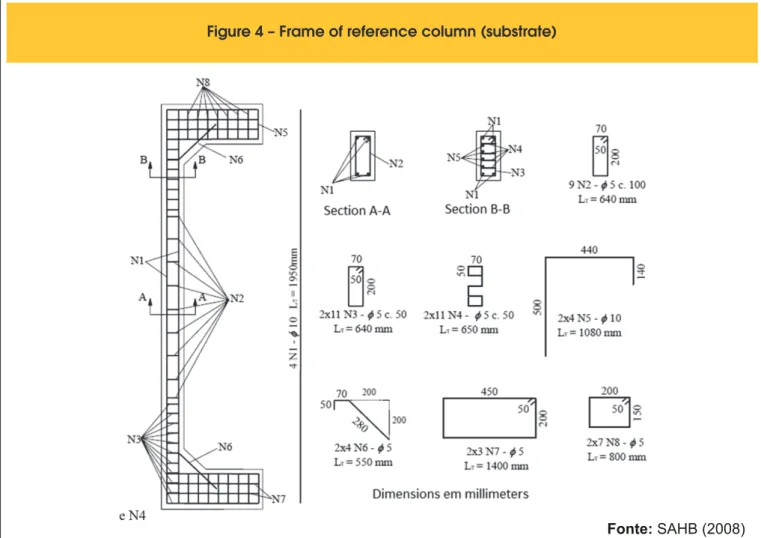
three-rein-forced pillars (P1, P2, P3) as described in Table [1].
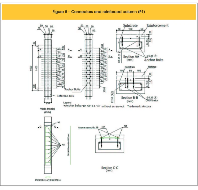
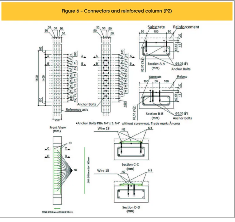
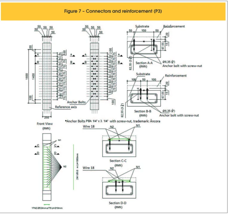
The geometric characteristics and the armature of the reference column followed dimensional patterns of the pillars Sahb assayed by [1], as shown in Figures [1], [2], [3] and [4]. The positioning and
number of bolts have been considered in the same P6-150-34 Vir -gin pillars [2] indicated in Figures [5], [6] and [7].
The surface of the pillar which received reinforcement was initially
pre-pared by receiving a chiseling by a pressure washer which projects wa -ter at high pressure (320 psi); The holes were then run through a drill,
control the depth thereof, so that inside the reinforcement of marking
executed in the form of pillars before the molding them, it was made
a template, so that the same were possible to mark the holes without
hitting a stirrup. After cleaning the surface and holes with compressed
air, the connectors are positioned and subsequently, are installed in the medium-carrying side as wetting surface. With the above steps ready,
the reinforcement frame has been tied to the connectors. The
reinforc-ing moldreinforc-ing was carried out with self-compactreinforc-ing concrete (SCC), thick
-ness of 35 mm with characteristic strength of 30 MPa.
2.2 Concrete substrate
In the molding of the pillars to be reinforced (substrate) was used
Figure 4 – Frame of reference column (substrate)
800 IBRACON Structures and Materials Journal • 2016 • vol. 9 • nº 5 ready-mix concrete. We used self-compacting concrete (SCC),
composed of Portland cement (360 kg / m³), ine natural sand (595 kg / m³), thick natural sand (175 kg / m³), crushed stone 0 (900 kgf / m³) , crushed stone 1 (110 kg / m³) water (180 l / m), multifunction additive (2.7 l / m³) and highplasticiser additives (2 l / m³) dosed to achieve an average compressive strength of 30 MPa at 28 days.
The compression strength of the concrete was obtained by two cy-lindrical specimens with dimensions of 150 mm height and diameter
equal to 300 mm. The values of resistance to compression of the
concrete pillar at the time of each test are presented in Table [2]. The tensile strength of the concrete was determined by the two con-crete test cylinder with the same dimensions as the previous ones, utilizing the diametric compression test. The lengthwise elastic mod-ulus was also obtained by means of two cylindrical test specimens.
Chose a 30 MPa concrete to get the same resistance adopted by Omar
[7] and Sahb [1]. The concrete was produced in central metering. The average compressive strength of concrete and the tensile
sub-strate, at the time of testing had average values equal to 44.2 MPa and 3.6 MPa, respectively, and the longitudinal elastic modulus Ini
-tial was equal to 31.4 GPa.
To determine the speciic properties of the substrate, both fresh,
and hardened, the prescribed procedures were followed in the fol-lowing standards: NBR 15823 [13], NBR 5738 [14], NBR 5739 [15], NBR 7222 [16], NBR 8522 [17].
2.3 Reinforcement of concrete
The strengthening of the pillars of the molding was also done
using self-compacting concrete, in order to obtain results similar to the concrete substrate (compressive strength and modulus of elasticity). The same was cast in the laboratory of CMEC
struc-tures (Master’s Degree in Civil Engineering - UFG). a dosing study
was conducted, characterizing and determining the trace materials in mass of concrete used in the reinforcement of the molding which
was equal to 1: 2.05; 1.36; 1.14; 0.76: 0.67 (cement, natural sand, artiicial sand, gravel 0, 1 crushed stone and water cement ratio - a / c). To achieve the required luidity and cohesion were also used 0.6% of multifunction additive, the super plasticizer 0.4% and 6%
active silica, both in relation to the cement content. For the me-chanical properties of the concrete used, they were carried out the same test run to the concrete substrate.
The average compressive strength of concrete and the tensile
sub-strate, at the time of testing had average values equal to 39.7 MPa and 3.8 MPa, respectively, and the elastic modulus was equal to 31.2 GPa.
2.4 Steel
For obtaining the characteristics of the steel used were tested two samples for each diameter (5.0 mm and 10.0 mm), using the test to simple traction according to the guidelines of the NBR 6152 [11]. They were determined by averaging the results of the samples the
value of the yield stress and the value of each speciic strain on the low of steel bars.
The steel bars of transverse reinforcement and strengthening
the equipment with a diameter of 5 mm showed no well-deined
802 IBRACON Structures and Materials Journal • 2016 • vol. 9 • nº 5
yield level, but we observed a change of direction in the graph stress versus strain, these specimens, thus determining the
voltage low and the speciic deformation of the same, since the
steel bars of the longitudinal reinforcement with a diameter of
10 mm were well deined yield level, obtaining the yield stress values and speciic deformation equal to 575 MPa and 2.50 mm / m (‰) respectively. For armor diameter equal to 5 mm, the re
-sults were 720 MPa yield strength and 3.5 mm / m (‰) speciic
deformation, respectively.
2.5 Steel anchor bolts
To strengthen concrete weld with the substrate, screws were used
bolts type PBA 5/16 “x 3¼” - C / P ANCHOR FIXING SYSTEMS.
With a diameter of 7.9 mm (5/16 “) total length of 82.55 mm (3 ¼”), average pullout load of 1430 kgf, assuming a hole with a minimum depth of 40 mm and 1 tightening torque 8 kgf.m, according to the
manufacturer’s technical catalog.
2.6 Form
The molding of the substrate of the reference columns and monolithic was performed with the use of metallic molds. The concrete cover 2.5 cm armor was secured with the use of plas-tic spacers, properly positioned in the armor. For concrete
rein-forcement, we used veneered laminated plywood, thickness 18 mm, positioned at the sides of the pillars and ixed by means of
metal staples.
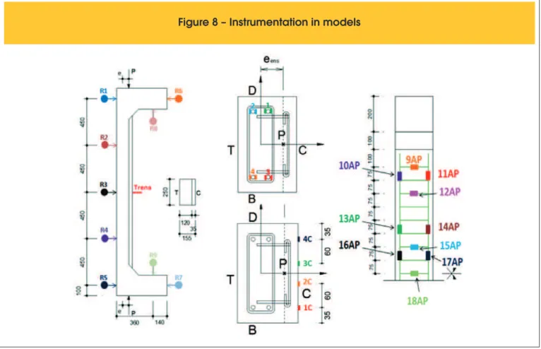
2.7 Instrumentation
To measure the deformations of the longitudinal reinforcing steel bars of the substrate and reinforcement of armor, respectively were bonded eight to ten electrical resistance strain gages (EER)
of the type PA-06-250BA-120-L and also, four strain gages at
the compressed side of the reinforcement such as PA-120-L-06-201BA both the EXCEL brand. The reading of the deformations of the gauges was performed by the data collection equipment AGI
-LENT BenchLink Data Logger Model 34970ª, Figure [8].
For measuring horizontal and vertical displacements of the pillars nine dial indicators were placed, Mitutoyo brand, with precision of
0.01 mm, named R1 to R9. The clocks were installed with the help
Table 2 – Comparative columns and failure modes
General comparative table
Column Age (days) fc (MPa)
Pult. leitura
(kN) Pu
(kN) Pu/
Pmon
Pu/
Pref Desl. R3 (mm) Desl. régua (mm)
εs,max/
εy
εs,max/
εu
Failure mode
(mm) Sub. Ref. Sub. Ref. (mm) (mm) (mm) (mm) (mm) (mm) (mm) (mm) (mm)
Pref 90 – 41,9 – 120,0 126,7 0,23 1,00 26,00 34,20 0,84 0,82 EA - EC Pmon 80 – 41,3 – 540,0 542,2 1,00 4,28 18,43 19,20 0,56 0,60 EA - EC
P1 192 19 45,9 40,0 400,0 510,0 0,94 4,03 7,42 17,50 0,58 0,71 DR
P2 191 18 45,9 39,4 420,0 522,0 0,96 4,12 4,63 15,00 0,60 0,61 DR
P3 187 14 45,8 26,9 500,0 501,4 0,92 3,96 11,20 17,40 0,41 0,57 DR
Sub.: Concrete susbrate (CAA); Ref.: Reinforcement concrete (CAA); fc: Strength of concrete compression; Pult. Reading: Load the last reading of the data collection
equipment; Pu.: Rupture load; Desl. R3: discplacement in translator R3; Desl. Scale: maximum displacement read on the scale; εs,max: maximum deformation in strain-gage
in steel bars in the substrate; εy: Yield steel bar; εc: Deformation in concrete by ABNT NBR 6118:2014; EA: Yield steel; EC: Crush concrete; DR: Peeling of reinforcement
804 IBRACON Structures and Materials Journal • 2016 • vol. 9 • nº 5 of magnetic base, ixed to a metal support structure and the cursor
on metal plates glued on the abutment as the positions shown in
the project, Figure [8].
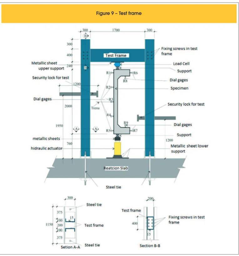
2.8 Experimental analysis
The pillars had two meters high and two consoles whose purpose was to allow the load to be applied eccentrically to the central
sec-tion. The central section represents the region of interest analysis. The strengthening of the consoles served only to ensure that the rupture occurred in the center section. The tests were performed in the laboratory of the Federal University of Goiás structures. The
load was applied by a hydraulic actuator, the Yelow Power brand, with nominal capacity of 1500 kN, triggered by a manual hydraulic
pump. The hydraulic actuator was positioned at the bottom of the column. To control the applied loading, a load cell with load reading
capacity of 1500 kN (Kratos) at the head of the column has been
positioned as shown in Figure [9]. The load was applied
consider-ing 100 kN load steps, coincidconsider-ing simultaneously with the readconsider-ing
of all instruments.
3. Results and discussions
All reinforced pillars obtained the last force larger than that the
abutment reference (P) and near of the load monolithic pillar (PMON), but still being smaller.
The resistive load expected of the models studied, was deined
based on the analysis in several similar previous studies and also depending on the results of numerical analysis of the same. It has been found that the use of the reinforcement armature little
inluence on the behavior of the models studied, and also did not
prevent the peeling of the reinforcement of concrete. All pillars had
rupture of the sudden kind, caused by strengthening peeling. Unlike the compressive strength of the concrete substrate and the reinforcement of concrete, the pillar P1 was 5.9 MPa, P2, P3 6.5 MPa and 18.9 MPa.
The reinforced pillars had a higher breaking load values as from
3.96 to 4.28 times the reference load of the pillar, as shown in Table
[2]. The pillars reached on average 94% load of the monolithic pillar.
On Table [2] there is a comparative analysis of all the pillars, with the concrete characteristics, last strength, larger displacement, greater deformation and failure modes.
It was observed that there was the appearance of various cracks in reinforced pillars, but it was not possible to check a critical crack
that could lead to rupture according of the loading increasing.
806 IBRACON Structures and Materials Journal • 2016 • vol. 9 • nº 5
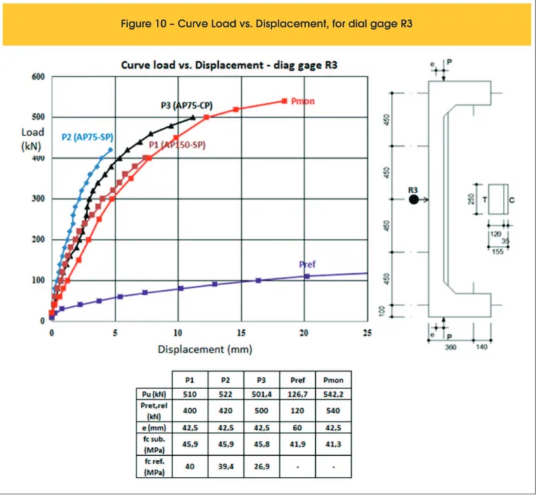
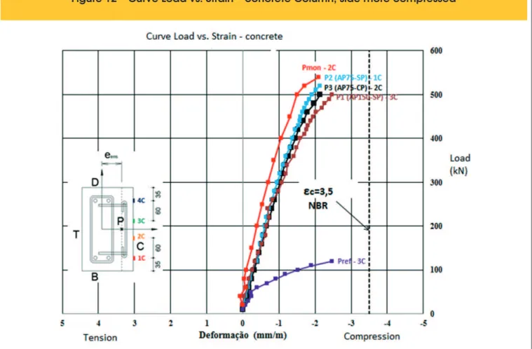
That’s because one of the pillars was rupture in the upper region, one in the central region and in the region below the surface stud-ied, occurring shortly after the peeling of the reinforcement. Before the reinforcement layer peeling, the pillars had a behavior similar to the monolithic pillar, both displacements, as shown in Figure
[10], as the deformations. They showed a tendency to low and crush -ing of concrete steel, Figures [11] and [12] characteristic of ductile
rupture, but the enhancement of peeling caused a sharp break in the
models. Since the reference columns and monolithic had a smooth
breakage, featuring a relatively ductile and gradual breakage.
The dial gauges were removed before the rupture of the pillars to be undamaged. After removal of the dial indicators reading the
shifts in R3 clock position, continued to be made by monitoring the naked eye, through the displacement of a measuring tape with mil -limeter scale, properly secured to the pillar. The largest
displace-ments were veriied by measuring tape and the dial indicator R3,
positioned in the central region of the T face of the pillars. Figure [11] shows the greatest deformation of the tensioned forcement (face T). Figure [13] shows the deformation of the rein-forcement of the reinrein-forcement bars in the most compressed re-gion (face C). The steel bars with a diameter of 10 mm (longitudinal reinforcement substrate) and 5 mm (reinforcing armature), were
properly characterized and obtained a low beginning of deforma
-tion (εy) 2.5 ‰ and 3.5 ‰, respectively.
The limit for the crushing of the concrete was adopted as indicated
in ISO 6118 [5], 3.5 ‰, considering the case of lexible pressing.
4. Conclusion
The last strength of the pillars P1, P2 and P3 were on average from
3.96 to 4.28 times greater than the inal column of the reference power and an average 94% load monolithic pillar employee con
-irming the enhancement of the eiciency and highlighting possibil -ity of using this type of reinforcement in structural rehabilitation, considering certain safety factor, in order to prevent the peeling of the reinforcement layer.
The displacements and deformations observed on the pillars P1, P2 and P3 were close to the monolithic pillar, but there was peeling of the reinforcement layer, causing a sharp break.
The variation in the spacing of the reinforcement of armor, had little
in-luence in the breaking loads and displacements of the studied pillars.
In none of the studied pillars was rupture of the anchor bolts.
So that the strengthening technique applied can be used in real
situations. However, it is necessary the use of safety factors and a thorough detailed analysis of the part to be rehabilitated. And then show a proper sizing model that will avoid peeling and follow normative policies.
5. Acknowledgements
On the Coordination of Higher Education Personnel Improvement - CAPES for inancial support in the form of the irst author. To
Redimix Concrete Brazil S.A. for the supply of materials for
mold-ing the concrete used. Mr. Divine Pedro Rocha for the transport of materials characterization. The Laboratory Carlos Campos Con
-sultoria e Projetos Ltda for the characterization of materials, con
-crete dosing study and availability of equipment and hand labor for professional pressure washer operation. At PUC-GO by steel bars
tensile testing.
6. Referências bibliográicas
[1] SAHB, K. F. P. Análise Experimental de Pilares de Concreto Armado Submetidos à Flexo-Compressão, Reforçados com Concreto Auto Adensável e Chumbadores. 224f. Disserta
-ção (Mestrado), UFG, Goiânia, Goiás, 2008.
[2] VIRGENS, P. J. Análise experimental de pilares de concreto armado, com carga excêntrica, reforçados com chumbadores
e concreto auto adensável (caa), REEC – Revista Eletrônica
de Engenharia Civil, volume 8, nº 1, Goiânia, Goiás, 2014.
[3] MARQUES, M. G. Análise do comportamento de pilares de concreto armado reforçados com chumbadores e concreto
auto adensável. 197f. Dissertação (Mestrado), UFG, Goiâ -nia, Goiás, 2014.
[4] FERREIRA, D. B.. Análise experimental de pilares de con -creto armado reforçados com con-creto auto adensável e
conectores. 199f. Dissertação (Mestrado), UFG, Goiânia,
Goiás, 2014.
[5] ABNT NBR 6118: Projeto de estruturas de concreto – Pro
-cedimento. Rio de Janeiro, 2014.
808 IBRACON Structures and Materials Journal • 2016 • vol. 9 • nº 5 [6] BASTOS, P. S. d. S., Fundamentos do Concreto Armado,
Bauru, São Paulo (UNESP), 2004, 107P. Notas de Aula. [7] OMAR, Mohamad Y.M. Análise experimental de pilares de
concreto armado reforçados com concreto auto adensável
(CAA). Dissertação (Mestrado) – Universidade Federal de Goiás, Goiânia, 2006.
[8] NASCIMENTO, P. P. Análise experimental de pilares de con
-creto armado submetidos à lexo-compressão, reforçados com concreto auto adensável e conectores. 205f. Disserta
-ção (Mestrado), UFG, Goiânia, Goiás, 2009.
[9] ARAÚJO, L. M. B. Análise teórico experimental de pilares de concreto armado submetidos à lexão normal composta. 196f. Dissertação (Mestrado), UFG, Goiânia, 2004.
[10] ADORNO, A. L. C. Análise Teórica e Experimental de Pila
-res em Concreto Simples e Armado sob Flexo-Comp-ressão
Reta. 399p. Tese (Doutorado) - Departamento de Engen
-haria Civil e Ambiental/UnB, Brasília, DF, 2004.
[11] ABNT NBR 6152: Metais metálicos – Determinação das pro
-priedades mecânicas à tração, Rio de Janeiro, 2002. [12] MELO, C. E. L. Análise Experimental e Numérica de Pila
-res Birrotulados de Concreto Armado Submetidos a
Flexo-Compressão Normal. Tese (Doutorado) - Departamento de Engenharia Civil e Ambiental/UnB, Brasília, DF, 2009. [13] ABNT NBR 15823: Concreto auto-adensável, Rio de Janei
-ro, 2010.
[14] ABNT NBR 5738: Concreto – Procedimento para Moldagem e Cura de Corpos-de-prova, Rio de Janeiro, 2007.
[15] ABNT NBR 5739: Concreto – Ensaios de compressão de Corpos-de-prova Cilíndricos, Rio de Janeiro, 2007.
[16] ABNT NBR 7222: Concreto e argamassa – Determinação da
resistência à tração por compressão diametral de Corpos-de-prova Cilíndricos, Rio de Janeiro, 2011.
[17] ABNT NBR 8522: Concreto – Determinação do módulo es