Safety variability assessment of reinforced concrete
beams subjected to bending moment considering the
NBR 6118:2014 safety partial factors
Avaliação da variabilidade da segurança de vigas
em concreto armado submetidas ao momento letor
considerando os coeicientes parciais de segurança
da NBR 6118:2014
a Universidade Estadual Paulista, Faculdade de Engenharia, Departamento de Engenharia Civil, Bauru – SP, Brasil.
Received: 08 Dec 2015 • Accepted: 12 Apr 2016 • Available Online: 23 Sep 2016
C. G. NOGUEIRA a
M. D. T. PINTO a
Abstract
Resumo
This paper presents a study about safety of reinforced concrete beams subjected to bending moment and designed with the partial safety factors proposed by ABNT NBR 6118:2014. The main goal was to assess the uniformity in the safety of the beams considering diferent values for the neutral axis position and the load ratio, by using the Reliability Theory. A simpliied procedure to calibrate the partial safety factors was proposed taking into account the nature of each random variable and a target reliability index. From the analysis of the results, an alternative method for the design of reinforced concrete beams was also proposed, in which safety is guaranteed by the using of a probability of failure instead a set of partial safety factors. The results showed the lack of uniformity in the safety of the beams design with de constant set of partial safety factors. The procedures of design and calibration of the new safety factors were capable of to give uniformity to the safety of the beams and to achieve the proper structural coniguration with the required safety level.
Keywords: reinforced concrete structures, partial safety factors, reliability, calibration.
Este artigo apresenta um estudo sobre a segurança de vigas em concreto armado solicitadas por momento letor dimensionadas com os coei-cientes parciais de segurança da ABNT NBR 6118:2014. O principal objetivo foi avaliar a uniformidade na segurança das vigas para diferentes posições da linha neutra e razão de carregamentos, com o uso da Teoria da Coniabilidade. Um procedimento simpliicado para a calibração dos coeicientes parciais de segurança foi proposto, levando-se em conta a natureza de cada variável aleatória e um valor alvo para o índice de con -iabilidade. A partir desses resultados, um método alternativo para o dimensionamento à lexão das vigas foi também proposto, no qual a seguran-ça é veriicada através de uma probabilidade de falha e não mais por coeicientes parciais. Os resultados mostraram a falta de uniformidade na segurança das vigas quando dimensionados com o conjunto ixo de coeicientes parciais. Os processos de calibração e dimensionamento alter-nativos mostraram-se capazes de uniformizar a segurança e ainda obter a coniguração estrutural que apresenta o nível de segurança requerido.
1. Introduction
The design of structures can be understood as an iterative process that seeks to establish dimensions and conigurations to the con-stituent elements of the structural system, in which a set of bounds is respected to guarantee the requirements of security, economic, aesthetic, functionality and durability. Within this context, the stan-dard design codes represent a fundamental role in the process, because they are the instruments that deine this acceptable lim -its set that ensure the performance requirements of the structural system. Regarding to the safety of the structure, the current codes are based on the Limit State Design which has to ensure for the diferent behaviors (limit states) governing the structural system the following condition: Rd ≥ Sd. In other words, the design value of the resistance (Rd) must always be greater than or equal to the de-sign solicitation (Sd). In each considered limit state, each of these portions depends on various parameters, such as: dimensions of the cross sections, resistance of materials, quantities of steel re-inforcement, positions of these reinforcements and internal eforts among others.
In the development of a project, after the design of the structural system, the next step is to quantify the acting loads on the structure and specify the materials used for the construction of structural el-ements, as well as its mechanical properties. However, there are uncertainties arising from the very nature of each parameter, as well as the procedures for obtaining the materials, use of construc-tion, construction techniques, methods of analysis and variations in loads that, and if not handled properly, can lead to an excessive risk, compromising the safety and/or the use of the buildings in an extreme situation. To consider the presence of uncertainties, the current design codes adopt the so-called safety partial factors. Such factors afect the loads increasing its efects and reducing the resistance of the material. So, after application of the safety factors, resistance and solicitation (reason the index “d” in R and S shown above) for each limit state considered in the project are ob-tained. In fact, with this procedure, it originates a safety margin re-garding to the magnitude of these adopted safety partial factors. In general, the greater these factors are, the greater the safety mar-gin and hence greater the limit state safety level. This approach improves the quantiication of structures performance because considers, in a more rational way, the uncertainties inherent to the design parameters and requires the explicit evaluation of security conditions for both situations: on service and to extreme states that indicate possible individual ruptures and/or the system as a whole (Ellingwood and Galambos [1]).
The safety factors, for many years, were determined according to the experience and judgment of professional manufacturers and even improved from accidents and disasters of buildings, show-ing the construction process of trial and error. It was only from the end of the 18th century that the irst structural calculations were recognized, being credited to Coulomb and Navier, while only at the end of the 20th century, advances in concepts and methods of structural analysis, accompanied by the development and dif-fusion of computers, allowed to better understand the behavior of structures, enabling signiicant improvements in engineering proj-ects (Ellingwood [2]). However, the uncertainties inherent in load-ing and material properties remained, so that, thanks to these un-certainties, the risks arise on the structural projects, giving rise to
occurrence of adverse events. The consequences in these cases can bring serious damage in terms of loss of human life and in economic aspects to the society. To avoid these types of events, the current design codes adopt again the safety partial factors to ensure that the behavior of the systems and the risks associated with projects remain within acceptable limits for the whole society. Given this, there are questions such as: a) if even with the use of safety factor there are still risks, how safe are currently designed structures? b) or, which is the “distance” in terms of security be-tween a service status and a possible situation of failure to a cer-tain limit state? In addition, before the advances in materials tech-nology, methods of numerical analysis and also fewer resources available for the construction of buildings, there is a need to im-prove the behavior prediction of structural systems, as well as to assess more consistently the safety of these structures. Thus, the deinition of the safety partial factors based on experience and pro -fessional judgment is no longer justiied, which introduce the need to calibrate these coeicients more rationally.
During the last decades, design codes based on the limit state method have calibrated the partial safety coeicients from proba -bilistic approaches. There are several criteria to perform the cali-bration process of these coeicients, so that resulting in a set of values that cover all structures belonging to a certain class, de-ined in the scope of the code [3-5]. The Reliability Theory has been used for such task, once the stochastic nature of the risks, accidental loads and material properties make evident the need of probabilistic treatment for coeicients calibration [2 and 6]. The great advantage of this approach is that the limit state method with calibrated safety coeicients based on probabilistic procedures, has transformed the classical integral that deines the problem of structural reliability [7] in a practical and direct way for use in proj-ects, even for professionals who are not familiar with the concepts of the Reliability Theory.
However, the design codes adopt a ixed set of partial safety fac-tors that are applied to all structures present in the implementation scope of the code. This assumption makes that diferent types of structural elements designed with such coeicients do not have uni -form safety levels for the various limit states. This approach tends to generate structural systems with reliability greater than minimum amounts required, oversizing structures. On the other hand, it is possible that the adoption of constants safety factors generates structures with global reliability lower than the recommended mini-mum values, which is clearly against the security situations [8-9]. In this context, Mohamed et al. [9] highlighted the lack of uniformity in the safety of pillars in reinforced concrete designed with partial fac-tors proposed by Eurocode 2, considering variations in important parameters like slenderness index, concrete resistance, axial load eccentricity and longitudinal steel reinforcement. After conirmation of lack of uniformity, a method was proposed for calibration of the coeicients on the basis of a uniform reliability level. Castillo et al. [10] presented a design methodology of reliability based opti-mization in which reliability constraints were incorporated into the formulation of the optimization problem. Thus, the safety partial factors applied to the used random variables were calibrated so that the designed structure present uniform reliability and minimum cost. The process was carried out considering the simultaneous occurrence of more than one failure mode in the design of a bridge crane beam. The authors found that in these cases the optimized
683
IBRACON Structures and Materials Journal • 2016 • vol. 9 • nº 5
design makes active one or more reliability constraints, calibrating the partial factors for these restrictions, but let the other restric-tions remain inactive exceeding the amount required for security in those restrictions. It is important to note that the same reliability target can produce several solutions that correspond to diferent combinations of partial factors, once the calibration process can be accomplished in several ways. A criterion to guide the choice of the best set of coeicients may be adopted as the one that generates the minimum cost structure (Gayton et al. [11]).
Stucchi and Santos [12] made a study on the design philosophy adopted in the Brazilian standards NBR 6118 [13] and North Ameri-can ACI 318-05 [14], comparing the reliability obtained for beams and slabs designed with both codes. Although the way to consider-ation of safety factor is diferent in both codes, the safety level ob-tained with each of them can be compared for reliability analysis. The authors also concluded that both design codes do not provide uniformity of safety in terms of the reliability index. However, the ACI showed better uniformity than the Brazilian standard, consid-ering various criteria of load combinations for the design of struc-tural elements, while the Brazilian standard uses only one combi-nation for live and dead loads.
Once detected the deiciency of design codes to provide uniform security for structures inserted in their categories, a current alterna-tive is to attempt to propose calibration methods of partial factors, in order to generate more uniform safety level. Beck and Souza Jr. [15] proposed a calibration procedure for the safety partial fac-tors of the Brazilian standards NBR 8800 [16] and American ANSI / AISC [17], from the solution of an optimization problem written in terms of the reliability indices obtained for structural elements compared with required values. Several loading ratios were tested between live and dead loads, as well as between wind and dead loads. The results showed that the new set of partial factors result-ed in greater uniformity of the elements designresult-ed with both codes. In this context, the main purpose of this paper is to evaluate the uniformity (or lack thereof) of the safety of reinforced concrete beams designed according to the criteria of NBR 6118 [13] con-sidering the proposed safety partial factors and the variation of the
relative position of the neutral axis and the active load ratios. Then, a process of safety partial factors calibration was proposed in order to standardize the safety of beams for the ultimate limit state of loss of load capacity to bending moment and, therefore, an alterna-tive design procedure of beams using reliability was performed and compared with the current procedure.
2. Flexural resistance of reinforced
concrete beams
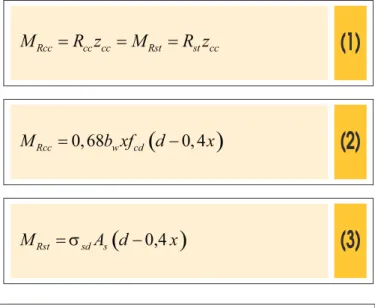
The resistance of reinforced concrete beams of rectangular cross-section to the bending moment comes from the classical equations of equilibrium (ΣN = 0 and ΣM = 0) and of the provisions recom-mended by the NBR 6118 [13]. Figure 1 shows the coniguration used to assess the resistance to bending moment in rectangular beams with simple reinforcement for values of fck ≤ 50 MPa. The internal resistant bending moment referent to the compressed concrete (MRcc) and tensioned reinforcement (MRst), as well as the bending moment resistance of the cross-section (MR) are given re-spectively by:
=
=
=
Rcc cc cc Rst st cc
M
R z
M
R z
(1)
(2)
(
)
0,68
0,4
=
-Rcc w cd
M
b xf d
x
(3)
(
0,4
)
=
-Rst sd s
M
s
A d
x
(4)
=
=
R Rcc Rst
M
M
M
Replacing the position of the neutral axis (x) by the dimensionless relative value (bx = x/d) in Equations (2) and (3) we have:
(5)
(
)
2
0,68
1 0,4
=
-Rcc w x cd x
M
b
b
d f
b
(6)
(
1 0,4
)
=
-Rst sd s x
M
s
A d
b
In the ultimate limit state, the moment resistance must be greater than or equal to the solicitation moment (Md), which determines the reinforcement area necessary for the beam as:
(7)
(
1 0,4
)
=
-
d s sd xM
A
d
s
b
The equilibrium equation in terms of horizontal forces (SN = 0 à
Rcc – Rst = 0) is given by:
(8)
0,68
b d f
wb
x cd-
s
sd sA
=
0
Where: bw is the cross section width; fcd is the design value for concrete compressive strength given by fck (characteristic value of concrete compressive strength) reduced by the safety partial factor gc = 1,4; ssd is the normal stress in the tensioned reinforce-ment, which depends on the neutral axis position. In cases of the deformation domains 2 and 3, which are the more usual situations where the beams are dimensioned to bending moment, the steel is already in yielding. So ssd can be replaced by fyk (characteristic value of the steel yield stress) divided by the safety partial factor gs = 1,15.
The equation 5, which is the result of the balance of moments in the cross section (SM = 0), can only be applied from the prior knowledge of the cross section height (d) and the relative neutral axis position (bx). Therefore, the design is inalized by adopting one of these variables and then applying the balance of the horizontal forces (Equation 8) to determine the other unknown variable. Both cases are quite used, the height of the beams can be adopted pre-viously in function of the pre-design or of architectural constraints of the project, as well as the neutral axis position can be set on the basis of normative criteria (ductility) and compatibility of deforma-tions. It is worth to mention that this description was not considered compression reinforcement.
Thus, it can be veriied that there are a variety of possible solutions for the cross section of the beams, as they adopt diferent values for the neutral axis position, even keeping the safety partial factors and the original height.
3. Reliability theory and methods
of analysis
In general, the main purpose of the structural reliability analysis is related to the probabilities determination of occurrence of scenari-os of interest related to the problem under study. More speciically, according to the several uncertainties inherent in the design pa-rameters of the structural system, as well as the structural analysis processes and even constructive methods, there will always be a probability of violation of one or more limit states which deine system behavior. Thus, the failure probability can be deined as a violation of a limit state. In this context, the limit states are rep-resented by mathematical functions described from deterministic and random parameters, setting a boundary between the security and failure regions in the ield of the problem possibilities. Math -ematically it can be expressed by:
(9)
(
,
)
=
(
1, , , ,
2¼
n)
G X U
f x x
x U
Where: X is the set of random variables; U is the set of determinis -tic parameters. When G = 0 one has the deinition of the event that causes the limit state.
Thus, each realization of the random set of system parameters that violates the limit state function is considered as a point in the failure domain of the problem. Let R is taken as a resistance ran-dom variable and S deined as a solicitation ranran-dom variable, both being dependent on X and U, one of the ways to write Equation (9) can be given by G = R – S. The failure probability (Pf) can then be deined as the probability of G < 0 and written by:
(10)
(
0
)
+¥( )
,
-¥-¥
=
- £
=
òò
sf RS
P
P R S
f
r s dr ds
Where: fRS is the joint probability density function of the variables R and S; r and s are the assumed values for R and S from each of the realization of the parameters of X and U.
However, the direct evaluation of failure probability by Equation (10) in practical terms is very complicated, since there is no known information about the joint probability density function of the ran-dom variables. To resolve this issue, several alternative methods have been developed to determine the failure probability, where we can mention the FORM, SORM, Response Surface Method and Monte Carlo Simulation Method among others.
in the standard normal space (FORM , SORM). More details about the methods can be found in Nowak and Collins [4].
4. Formulation of the problem
before calibration
The initial problem before the calibration proposal of the safety par-tial factors was formulated from the possibility of obtaining several diferent solutions to the same beam depending on the neutral axis position in cross section. In addition, in order to verify the inluence of the live loads on the safety of the beams, it was considered a set of load ratios (R) as deined by the ratio between the nominal bending moments from the live loads (Mnq) and dead loads (Mng). The following values for the relative neutral axis position were: 0,167; 0,200; 0,231; 0,259; 0,280; 0,304; 0,333; 0,412; 0,466; 0,500; 0,538; 0,608 and 0,628. Similarly, the load ratios assumed the following values: 0,1; 0,3; 0,5; 0,7; 0,9; 1,1; 1,3 e 1,5. The con-crete and steel resistance values were kept constant in the study with fck = 20 MPa and fyk = 500 MPa, respectively.
In the irst step, the reinforced concrete beams were design to bending moment considering constant values for the cross-sec-tion’s width of 14 cm and efective depth of 45 cm (overall thick-ness of 50 cm). The safety partial factors were kept the same as recommended by NBR 6118 [13], i.e. gc = 1,4 and gs = 1,15. Given these parameters and each value for the relative position of the neutral axis, the tension reinforcement area was dimensioned from Equation (8). With the tensioned reinforcement values, the bend -ing moment resistance of the cross section was obtained for each neutral axis position by Equation (6).
Then, the reliability analyzes were performed for the diferent designed cross-sections in the previous step. In this step, the re-questing bending moments were deined from the moment resis-tance of the beam, as:
(11)
=
+
R g ng q nq
M
g
M
g
M
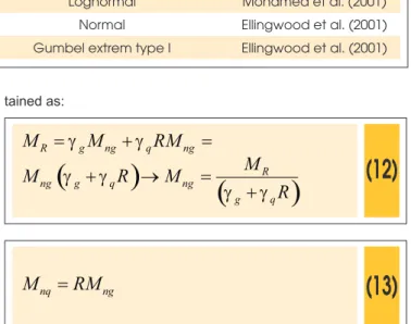
Where: MR is the bending moment resistance of the cross sec-tion, which is, in the design condisec-tion, equal to the total request -ing bend-ing moment; Mng and Mnq are respectively the requesting nominal bending moments relating to dead and live loads; gg and gq are respectively the safety partial factors that provide security for dead and live bending moments, both adopted as 1,4.
Once the load ratio is given by R = Mnq / Mng and was varied from 0,1 to 1,5 as previously described, the solicitation values were
ob-tained as:
(12)
=
+
=
R g ng q ng
M
g
M
g
RM
(
+
)
®
=
(
)
+
Rng g q ng
g q
M
M
R
M
R
g
g
g
g
(13)
=
nq ng
M
RM
The random variables considered in the study were: compressive strength of the concrete (fc), strength of the steel (fy), dead bending moment (Mg) and live bending moment (Mq). Table 1 shows the statistics associated with the variables in order to take into account the uncertainties.
The limit state equation that represents the safety of reinforced concrete beams is given by:
(14)
=
R-
g-
qG M
M
M
(15)
(
)
2 2
0,408
1
=
+
-R w c x s y x
M
b f d
b
A f d
b
The reliability analyzes were performed considering the FORM with direct coupling, in which the derivatives of G are evaluated im-plicitly by inite diferences. The convergence in the search process was written in terms of failure probability and design point with an error tolerance of 10-4.
5. Results before calibration
Table 2 illustrates the averages of random variables, considering each of the load ratios as well as the reliability indices (b) obtained in the analysis. All these results refer to a single value of the rela-tive position of the neutral axis. This process was repeated for all other values of bx, leading to 104 analyzes in total.
Figure 2 shows the results of the beams analyzes in terms of
Table 1 – The adopted random variables on the problem
Random variable Mean C.O.V. Probability distribution Reference
fc (MPa) 25 12% Lognormal Mohamed et al. (2001) fy (MPa) 550 6% Lognormal Mohamed et al. (2001) Mg (kNcm) 1,05×Mng 10% Normal Ellingwood et al. (2001)
687 IBRACON Structures and Materials Journal • 2016 • vol. 9 • nº 5
C. G. NOGUEIRA | M. D. T. PINTO
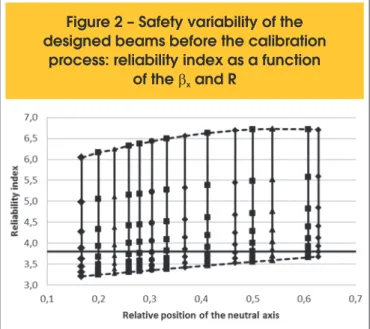
variability of the reliability index considering the diferent neutral axis positions for all load ratios. The horizontal line represents the target value of b = 3,8 recommended by Eurocode 2 [20] to the ul-timate limit state. The vertical lines contain the results for all values of R for the same neutral axis position, in which the top points are referred to R = 0,1 while the bottom points represent R = 1,5. Considering all the possibilities for the neutral axis position in the same cross section and the several load ratios, the reliability in-dex resulted from bmin = 3,21 and bmax = 6,72 relecting in failure probabilities Pf,min = 8,89×10
-12 and P
f,max = 6,64×10
-4. This large diference shows the lack of uniformity in the safety of the beams designed with the ixed set of partial safety factors. Furthermore, it was found that in some cases the reliability index resulted lower than the limit values recommended by Eurocode 2, which is clearly a design situation against the safety. The design situations with higher values of R, in the case where the live portion of moment increases in relation to the dead moment resulted in lower rates of reliability when compared to beams designed for lower load ratios. This is consistent because the uncertainties present in quantify -ing live loads are signiicantly higher than those observed in the dead loads, which results in less structural safety. Similarly, as the overall thickness of the beams was always kept constant, larger values of bx also resulted in larger values of resistant bending mo-ments, which suggest an increase in the bending resistance of the beam, since the amount of longitudinal reinforcement increases. Therefore, for situations where the overall thickness of the beams is limited by architectural issues and kept constant, higher values in the neutral axis provide larger values for the resistant bending moment. However, it is worth to mention in such cases, the failure may occur by the concrete crushing on the top ibers of the cross section. This condition must always be avoided in the design of reinforced concrete beams because it changes the behavior of the beams from ductile to brittle resulting in a very dangerous situation in designing. For such reason, the NBR 6118 [13] restricts the rela-tive neutral axis position as a function of the concrete compressive strength in order to avoid structures with a brittle behavior and high amounts of longitudinal reinforcement.
The average values for the reliability index for each of the neutral axis position resulted, in general, between 4,0 and 5,0. This means that, on average, the design of reinforced concrete beams consid-ering the safety partial factors of NBR 6118 [13] is acceptable and yet not so distant from the target value of b = 3,8.
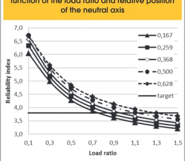
In Figure 3 it was represented the evolution of reliability index for some values of the relative neutral axis position depend-ing on the load ratio. It was observed as the effect of live load increases on the structural behavior, the safety level of the beams decreases. In this case, as the depth of the cross sec-tion was kept constant, higher values of bx result in greater safety to the bending moment. Considering bx = 0,500, it was verified that only values of R ≥ 1,1 the obtained b was less than 3,8. For load ratios between 0,3 and 0,7 which match the many of the usual situations in practice in reinforced concrete structures, the reliability index resulted between the values 4.0 and 5.0 as already noted. This shows that for beams designed in the domain 3 of deformation, the safety against bending mo-ment is assured.
However, it is worth to note that due to the lack of uniformity ob-served, the use of ixed set of partial factors can lead to design structures against security. On the other hand, it is also possible that the designed beams present an excessive safety level, such as observed in cases where the live loads are very small when compared to dead loads. In such cases, it is clearly observed that
Table 2 – Results in terms of reliability index for
b
x= 0,167
fck (MPa) R fc,mean (MPa) fy, mean (MPa) Mg,mean (kNcm) Mq,mean (kNcm) b
20
0,1
25 550
2926,3 278,7 6,04
0,3 2476,1 707,5 4,98
0,5 2146,0 1021,9 4,28
0,7 1893,5 1262,3 3,88
0,9 1694,2 1452,2 3,62
1,1 1532,8 1605,8 3,44
1,3 1399,6 1732,8 3,31
1,5 1287,6 1839,4 3,21
Figure 2 – Safety variability of the
designed beams before the calibration
structures result oversized and at the same time anti-economical. Another result that deserves to be discussed is the sensitivity of ran-dom variables and its evolution over the parametric analysis. Figure 4 illustrates the average sensibilities of the variables obtained con-sidering all the load ratios for some relative position of the neutral axis. As no ductility constraint was imposed in the analysis, it was observed that the importance of concrete resistance increases as the position of the neutral axis also increases. On the other hand, the resistance of steel sufers the reverse process. As the position of the neutral axis increases, the portion of the concrete in bending mo-ment also increases, while the portion of reinforcemo-ment decreases, as can be seen in equation (15). Regarding to the requesting bend-ing moments, the portion of variable moment is much more
inluen-tial than the portion of the permanent bending moment. This behav-ior becomes more evident, as the load ratios R increases.
6. Formulation of the problem
for calibration
In order to obtain more uniform safety levels in the design of re-inforced concrete beams subjected to bending moment, it was performed a calibration procedure of safety partial factors of the random variables based on the procedure proposed by Mohamed et al. [9]. In general, the partial safety factors acting as resistance reducers (gR) or increasers (gS) of the load efects can be written as:
(16)
=
kR d
X
X
g
(17)
=
d fk
X
X
g
Where: Xk and Xd are, respectively, the characteristic values and design values of the considered parameters.
In case of the characteristic values, these are obtained from the quantile, which ensure that the overcoming of such values is very unlikely (in general, it allows to 5% quantile value). As for the de-sign values, these are deined by the reliability analysis, in which the coordinate of the design point related to the analyzed variable (X*) is given in the standard normal space by:
(18)
*=
=
-d X
X
X
a b
Where: aX corresponds to the cosine director of the random vari-able X; b is the reliability index obtained in the iteration.
According to Mohamed et al. [9], the characteristic value of a vari-able, regardless of the probability distribution can be written in func-tion of the average (mX) and the standard deviation (sX) in the form: Xk = mX ± dsX , where d expresses the probability (conidence level) that the Xk value is exceeded. In the case of compression strength of the concrete, assuming normal distribution and the probabilities of 5% quantile for setting the characteristic value, d takes on a value of 1,645. For the other probability distributions, Xk can be given generally by:
(19)
[
>
]
(
)
®
=
-1( )
1
-k k X
P X X variável resistência
X F
p
( 2 0 )
(20)
[
<
]
(
)
®
=
-1( )
k k X
P X X variável solicitação
X F p
Figure 3 – Variation of the reliability index in
function of the load ratio and relative position
of the neutral axis
Figure 4 – Variation on the random variables
sensitivity regarding to failure probability of the
689 IBRACON Structures and Materials Journal • 2016 • vol. 9 • nº 5
C. G. NOGUEIRA | M. D. T. PINTO
Where: FX–1 is the inverse of the cumulative probability distribution of the random variable; X is the current value of the random variable; p corresponds to the level of conidence which deines the required probability for the variable violates the characteristic value. In the case of a resistance variable and 5% conidence level, the probability that the value considered to overcome resistance Xk is 95%. On the other hand, for a solicitation variable with the same level of conidence, in just 5% of the time the value considered can overcome Xk.Therefore, the equations (16) and (17) can be rewritten, respectively, as:
(21)
(
)
(
)
1 1
1
Φ
-=
=
é
-
ù
ë
û
X k
R
d X X
F
p
X
X
F
g
a b
(22)
(
)
( )
1 1
Φ
-é
-
ù
ë
û
=
d=
X Xf
k X
F
X
X
F
p
a b
g
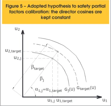
Where: F is the standard normal cumulative probability function. The adopted hypothesis for the safety partial factors calibration consists in choose a target value for the reliability index and admit that the co-sines directors of the random variables are kept constant. With that, the origin of standard normal system is moved so that the distance from the origin to the design point is equal to the target reliability index (Figure 5). For the calibration process, the target reliability index was 3,8 rec-ommended by Eurocode 2 [20] to ultimate limit states. The used cosines directors of random variables were obtained by the reliabil-ity analysis, via FORM, performed in the previous step, i.e., during the safety evaluation of the beams before calibration.
In order to verify all the possibilities in the calibration process, the safety partial factors were obtained considering all the values of the relative position of the neutral axis for each load ratio. Thus, there were 104 calibrations of partial factors covering all cases in-tended for the beams design.
7. Results after calibration
Table 3 shows the results obtained with the calibration process, in terms of the new safety partial factors, the design point
coordi-nates in physical space and reliability indices for bx = 0,167 in all load ratios.
Figure 6 illustrates the reliability indices of the beams designed with the new values of safety partial factors, considering all combinations between load ratios and the relative position of the neutral axis. As can be seen, the design of beams using the calibrated partial factors resulted in uniformity of the safety for the bending moment, achieving the target value of 3,8 speciied for the ULS.
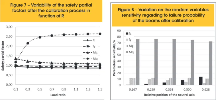
Figure 7 shows the safety partial factors for each load ratio, ob-tained by assessing the arithmetic mean between the values cali-brated to the diferent relative positions of the neutral axis. The par-tial factors for the resistance of concrete and steel resulted slightly less than unity, meaning that the characteristic values are more pessimistic than the design values. The partial factor for the dead load ranged from 1,09 (R = 1,5) and 1,35 (R = 0,1), whereas for the live load, the variation was 1,18 (R = 0,1) to 2,64 (R = 1,5). As R increases and, therefore, the importance of the live load increases, consequently, the value of its partial factor also increases. High
Figure 5 – Adopted hypothesis to safety partial
factors calibration: the director cosines are
kept constant
Table 3 – Results of the calibration process for
b
x= 0,167
R fc (MPa) fy (MPa) Mg (kNcm) Mq (kNcm) gc gy gg gq b
values above 2.00 relect the greater uncertainty inherent in this variable when compared to the others.
Regarding to the sensitivity factors of the random variables, the same general behavior was observed when compared to prior calibration results, as can be seen in Figure 8. The inluence of concrete and steel strength variables is signiicantly sensitive to the relative position of neutral axis, alternating its importance as bx increases. Since the parameters that depend on the dead and live loads, in which case are given by the bending moment, are more sensitive to variations in the load ratio than the neutral axis position.
The results showed that due to the calibration of safety partial fac-tors of the resistances and active loads, it was possible to obtain uniformity in the safety of reinforced concrete beams subjected to bending moments. Thus, instead of using a single set of partial
factors for all types of structures or design possibilities, a set of these coeicients are calibrated considering the particularities of each project, so that the desired safety level is actually achieved. The main disadvantage of this approach is not to present a ixed set of safety partial factors, which in principle can cause strange-ness among design engineers. Moreover, the calibration of these coeicients requires knowledge, even if minimum, on statistical concepts and reliability theory. Such concepts are not easy-going and wide domain among professionals who work in the practice of the current structural engineering. However, the approach brings a major advantage: from the partial factor calibration process it is possible to specify and obtain the security level of the structural system according to the particular needs of each project. Thus, even if important parameters as the load ratios and the neutral axis are changed in design, the security obtained for the system remains the same.
Another important aspect that should be discussed is related to the possibility of obtaining a set of safety partial factors for the target reliability can be achieved. By varying each of the safety factors values for more or less, it is simply necessary to adjust the others parameters to keep the same reliability index, showing the various possibilities for adoption of the safety partial factors. Thus, the use of other criteria in addition with the calibration process is neces-sary to achieve the best partial factors, as for example, the solution with minimum cost regarding the designed coniguration so that the optimal solution is reached. The minimum cost criterion in the calibration process was not considered in this paper.
8. Proposal for a simpliied
design method
Based on the results obtained with the safety partial factors cali-bration process, it was proposed a simpliied alternative method for design reinforced concrete beams subjected to bending moment, whose steps are described below:
Figure 6 – Safety variability of the designed
beams after the calibration process: reliability
index as a function of the
b
xand R
Figure 7 – Variability of the safety partial
factors after the calibration process in
function of R
Figure 8 – Variation on the random variables
sensitivity regarding to failure probability
691 IBRACON Structures and Materials Journal • 2016 • vol. 9 • nº 5
C. G. NOGUEIRA | M. D. T. PINTO
1. Select the desired security level, setting a value for the target reliability index;
2. Select the relative position of the neutral axis in the cross sec-tion for the ultimate limit state;
3. After the measurement of the loads on the beam, the load ratio R is assessed;
4. Evaluation of the cosines directors (ai) for each random vari-able in the process, which in the case are: fc, fy, Mg e Mq; 5. Evaluation of the safety partial factors of the variables from the
Equations 21 and 22;
6. Designing of the cross section of the beam, obtaining the efec -tive depth and tension reinforcement area.
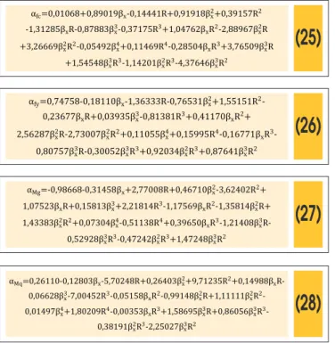
The greatest diiculty in this process is to determine the cosine di -rectors of the design variables. The most direct way is to conduct a reliability analysis via FORM, for example, to obtain these sensitivi-ties from the statistics of the random variables. However, the use of this alternative would be quite restricted to the domain of strong computational tools for evaluating the structural reliability, prevent-ing the application of this alternative design method. In order to overcome this problem, it was proposed an approximate way to get the cosine directors without the need to perform reliability analysis. As the relative position of the neutral axis and the load ratio are important parameters for the structural safety of the beams, a set of complete polynomials with 2º and 4º degrees for approaching each cosine director directly were adopted. Nogueira and Pinto [18] presented results of this procedure considering polynomials of 2º degree and concluded that the inal level of safety obtained oscillated around the value the reliability index target. The authors concluded that the 2º degree polynomials were not suiciently able to accurately represent the results of cosine directors obtained in reliability analysis. Furthermore, the study found values of R
be-tween 0.1 and 5.0 with non-constant variation, which increased the dispersion of the results, impairing the quality of the calibration. In general, the complete polynomials of 4º degree considered can be written as:
(23)
α
i=m
0+m
1β
x+m
2R+m
3β
2x+m
4R
2+m
5β
xR+m
6β
x3+m
7R
3+m
8β
xR
2+m
9β
x2R
+m
10β
x2R
2+m
11β
x4+m
12R
4+m
13β
xR
3+m
14β
x3R+m
15β
x3R
3+m
16β
x2R
3+m
17β
x3R
2Where: mi are the coeicients of the considered polynomial of co-sines directors to be determined.
The least square method was used to determine the polynomials coeicients from the minimization of the error function given by:
(24)
(
)
2, 1
,
=
é
ù
=
å
npë
x i-
FORM iû
ierro min
a b
R
a
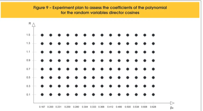
Where: a(bx, R)i corresponds to the cosine director value of the variable considered for the point i; aFORM,i is the value of the same cosine director, however from the original reliability analysis via FORM; np is the number of points of the considered experiment plan for the regression process. The solution algorithm of Equation (24) is described in details in Nogueira [19].
The experiment plan used to solve this problem was deined from all combinations considered among bx and R in the process of the safety partial factors calibration, as illustrated in Figure 9.
(25)
αfc=0,01068+0,89019βx-0,14441R+0,91918βx2+0,39157R2
-1,31285βxR-0,87883βx3-0,37175R3+1,04762βxR2-2,88967βx2R
+3,26669βx2R2-0,05492βx4+0,11469R4-0,28504βxR3+3,76509βx3R
+1,54548βx3R3-1,14201β2xR3-4,37646βx3R2
(26)
αfy=0,74758-0,18110βx-1,36333R-0,76531βx2+1,55151R2
-0,23677βxR+0,03935βx3-0,81381R3+0,41170βxR2+
2,56287βx2R-2,73007βx2R2+0,11055βx4+0,15995R4-0,16771βxR3
-0,80757βx3R-0,30052βx3R3+0,92034βx2R3+0,87641βx3R2
(27)
αMg=-0,98668-0,31458βx+2,77008R+0,46710βx2-3,62402R2+ 1,07523βxR+0,15813βx3+2,21814R3-1,17569βxR2-1,35814βx2R+ 1,43383βx2R2+0,07304βx4-0,51138R4+0,39650βxR3-1,21408βx3
R-0,52928βx3R3-0,47242β2xR3+1,47248βx3R2
(28)
αMq=0,26110-0,12803βx-5,70248R+0,26403βx2+9,71235R2+0,14988βxR-0,06628βx3-7,00452R3-0,05158βxR2-0,99148βx2R+1,11111βx2R2
-0,01497βx4+1,80209R4-0,00353βxR3+1,58695βx3R+0,86056βx3R3
-0,38191βx2R3-2,25027βx3R2
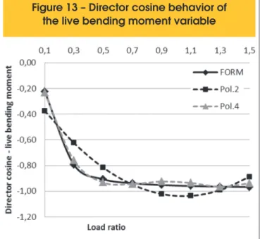
Figures 10 to 13 illustrate the accuracy of the 4º degree polynomial to obtain the cosine directors, compared to the solutions given by Nogueira and Pinto [18] with a 2º degree polynomial and the FORM. With that, during the design of the beams with the proposed method, it is suicient to calculate the values of the cosine directors by Equa-tions (25) to (28) without the need for auxiliary reliability analysis.
9. Calculation example
To demonstrate the application of the simpliied method proposed in this study, a reinforced concrete beam was designed to bend-ing moment, varybend-ing the use of the structure and consequently
the load ratio. Figure 14 shows the characteristics of the ictitious pavement considered as well as the beam V2 chosen for design. The dead loads were estimated considering: reinforced con-crete solid slab with a thickness of 10 cm; regularization on the slab of cement and sand mortar with a thickness of 2 cm; ce-ramic loor on the regularization with speciic weight of 18 kN/ m3 and a thickness of 6 mm; coated liner on the bottom of the slab composed of cement and sand mortar with a thickness of 1 cm. All values of the speciic weights of the materials were ob -tained from NBR 6120 [21]. The total dead load on the slab was 3,24 kN/m2, which resulted in uniformly distributed dead load (g) transmitted to the beam V2 with 16,2 kN/m. Regarding the live load (q) considered over the entire slab, the recommended val -ues have been adopted by the NBR 6120 [21] according to the building functionality. Thus, the following legend was adopted: A - terraces or liners without people access; B - bedrooms, liv-ing room, kitchen and bath; C - pantry, laundry area and laundry room; D - reading room in libraries; E - garages for common vehicles; F – stadium bleachers; G - dance hall and
gymna-Figure 10 – Director cosine behavior
of the concrete strength variable
693 IBRACON Structures and Materials Journal • 2016 • vol. 9 • nº 5
C. G. NOGUEIRA | M. D. T. PINTO
sium. These nomenclatures are placed in the “Type” column in Table 4.
For comparative purposes, the beams were designed consid-ering the conventional safety partial factors of NBR 6118 [13] and then considering the calibrated partial factors in accordance with the proposed process. The width of the beam was kept constant at the value of 14 cm and the characteristics resistance of concrete and steel was adopted, respectively, in the amounts
of 20 MPa and 500 MPa. The safety factors were calibrated to reliability index target of 3,8. In all cases the relative position of the neutral axis at ULS was adopted and kept constant at 0,45 for that the ductility constraint imposed by the NBR 6118 [13] always have been respected. Table 4 gathers the results of this analysis. As can be seen, the major diferences between the two calculation methods are for low values of the load ratio. This shows that in situations where live loads are signiicantly small-er than the dead loads, the partial factors used by NBR 6118 [13] lead to excessively secure design. This behavior changes as R increases, where the security level of the beams tends to decrease, violating the limit of 3,8 proposed by Eurocode 2 [20]. Thus, the lack of uniformity in the beams security is evi-dent. Moreover, when calibrating the partial factors according to the project need, it is possible to obtain uniformity of structural safety, as the reliability index values obtained in the analysis. The bmedium obtained with the proposed method was 3,80 while for the model of NBR 6118 [13] was 4,50, which demonstrates once again that the proposed calibration procedure allows, be-sides reaching the target security level speciied in the design, ensure uniformity of structural safety.
10. Conclusions
In this article it was presented a study about the safety of rein-forced concrete beams designed to bending moment, considering the set of partial factors for resistance of the materials (steel and concrete) and the action efects (permanent and variable bending moments) through the reliability theory. After the performed ana-lyzes, the following conclusions were highlighted:
Figure 13 – Director cosine behavior of
the live bending moment variable
Table 4 – Design of the beams considering the set of calibrated
safety factors and the standard ones
Proposed method NBR 6118
Type q (kN/m2) R d (cm) A
S (cm2) b d (cm) AS (cm2) b
A 0,5 0,14 40,15 7,01 3,70 49,50 6,97 6,51
B 1,5 0,42 46,84 8,43 3,86 55,20 7,77 4,92
C 2,0 0,56 50,44 9,16 3,90 57,85 8,14 4,51
D 2,5 0,70 53,43 9,75 3,83 60,39 8,50 4,24
E 3,0 0,84 56,13 10,27 3,75 62,82 8,84 4,03
F 4,0 1,11 62,06 11,38 3,77 67,41 9,49 3,75
G 5,0 1,39 68,31 12,55 3,88 71,72 10,09 3,56
n It has been found, indeed, the lack of uniformity in the safety of the beams subjected to bending moment when they are always designed with the same values of safety partial fac-tors for diferent situations of the neutral axis position and load ratios. Using the same safety partial factors values does not take into account the inluence of the neutral axis position and the ratio of the efects produced by the dead and live loads on the behavior of the beams. Thus, for low values of R, the security level obtained is too high, while for high values of R, the level decreases, resulting in situations against security;
n The proposed calibration process of the safety based on the results of reliability analysis was stable and capable of en-suring the reliability index target for beams designed with the new partial factors. Polynomials with degree of 4 to cal-culate the cosine directors of the project variables were ade-quate, because they allowed the design method was applied without the need for new reliability analysis, achieving good results. Thus, the uniformity was guaranteed in the safety of the beams subjected to bending moment;
n Therefore, instead of using a ixed set of safety partial
fac-tors, the method proposes the adoption of the security level required in the project through the reliability index or failure probability for the considered limit state and, from that in-formation, calibrate the partial factors to achieve this level of safety;
n It is worth to note that, there are several of possible com-binations to partial factors that result in the same values of reliability index. Thus, it is necessary to quantify the costs of the beams construction designed with new safety factors, compare them with the costs obtained with the standard process and assess what the optimal set of factors ensures the required safety, relecting the lower cost to the structure. This cost analysis was not performed in this work and is cur-rently under development.
11. Acknowledgements
The authors would like to acknowledge UNESP - FEB for the sup-port in the research development.
12. References
[1] ELLINGWOOD, B.; GALAMBOS, T.V. Probability-based criteria for structural design. Structural Safety, v.1, 1982; p.15-26.
[2] ELLINGWOOD, B. LRFD: implementing structural reliability in professional practice. Engineering Structures, v.22, 2000; p.106-115.
[3] SØRENSEN, J.D.; KROON, I.B.; FABER, M.H. Optimal reli-ability-based code calibration. Structural Safety, v.15, 1994, p.197-208.
[4] NOWAK, A.S.; COLLINS, K.R. Reliability of structures. Mich-igan: McGraw-Hill, 2000, 338 p.
[5] MADSEN, H.O.; KRENK, S.; LIND, N.C. Methods of struc-tural safety. Prentice-Hall, Englewood Clifs, N.J., 1986. [6] HAN, B.K. Reliability assessment and design load factors for
reinforced concrete containment structures. Reliability Engi-neering and System Safety, v.62, 1998, p.235-240.
[7] FREUDENTHAL, A.M. The safety of structures. Transac-tions of ASCE, v.112, 1947, p.125-180.
[8] KOGUT, G.F.; CHOU, K.C. Partial resistance factor design on steel-concrete beam-columns. Engineering Structures, v.26, 2004, p.857-866.
[9] MOHAMED, A.; SOARES, R.; VENTURINI, W.S. Partial safety factors for homogeneous reliability of nonlinear re-inforced concrete columns. Structural Safety, v.23, 2001, p. 137-156.
[10] CASTILLO, E.; CONEJO, A.J.; MÍNGUEZ, R.; CASTILLO, C. An alternative approach for addressing the failure proba-bility-safety factor method with sensitivity analysis. Reliability Engineering and System Safety, v.82, 2003, p.207-216. [11] GAYTON, N.; MOHAMED, A.; SORENSEN, J.D.;
PEN-DOLA, M.; LEMAIRE, M. Calibration methods for reliability-based design codes. Structural Safety, v.26, 2004, p.91-121. [12] STUCCHI, F.R.; SANTOS, S.H.C. Reliability based compari-son between ACI 318-05 and NBR 6118. IBRACON Struc-tural Journal, v.3, n.2, June, 2007, p.230-239.
695 IBRACON Structures and Materials Journal • 2016 • vol. 9 • nº 5
C. G. NOGUEIRA | M. D. T. PINTO
[14] ACI COMMITTEE 318, Building code requirements for struc-tural concrete (ACI 318-05) and commentary (318R-05), American Concrete Institute, Farmington Hills, Michigan, 2005, 430 p.
[15] BECK, A.T.; SOUZA JR, A.C. A irst attempt towards reliabili-ty-based calibration of Brazilian structural design codes. J. of the Braz. Soc. Of Mech. Sci. & Eng. v.XXXII, n.2, April-June, 2010, p.119-127.
[16] BRAZILIAN ASSOCIATION OF TECHNICAL STANDARDS (ABNT). Design of steel and steel-concrete composite structures: procedures (NBR 8800), Rio de Janeiro, 2008. (in Portuguese)
[17] ANSI/AISC 360. Speciication for structural steel buildings. American Institute of Steel Construction, Chicago, Illinois, 2005.
[18] NOGUEIRA, C.G.; PINTO, M.D.T. Análise de coniabilidade de vigas em concreto armado segundo a ABNT NBR 6118: avaliação da segurança e calibração dos coeicientes parci -ais de segurança. In: 56º Congresso Brasileiro do Concreto, Natal, 2014, Anais, Rio Grande do Norte, 2014.
[19] NOGUEIRA, C.G. Desenvolvimento de modelos mecânicos, de coniabilidade e de otimização para aplicação em estrutu -ras de concreto armado. Tese de Doutorado, Escola de En-genharia de São Carlos, Universidade de São Paulo, 2010. [20] EUROCODE 2. Design of concrete structures. Part 1:
gen-eral rules and rules for buildings. Brussels: CEN, 1989. [21] BRAZILIAN ASSOCIATION OF TECHNICAL STANDARDS