Abstract
Abrupt track vertical stiffness variations along railway tracks can lead to increased dynamic loads, asymmetric deformations, damaged track components, and consequently, increased maintenance costs. The junction of slab track and ballasted track is one of the existing areas where vertical track stiffness can suddenly change, therefore requiring a transition zone that smoothes the track stiffness change. One of the methods for constructing the transition zone at the junc-tion of slab and ballasted tracks is to install auxiliary rails along the transition zone. In the present study, the dynamic behavior of this type of transition zone was evaluated by a train-track interaction model. For this purpose, a 3D model of the railway track was made, representing the slab track, the transition zone, and the ballasted track. Then, the modeling results were validated by the results of field tests. Afterwards, in order to study the dynamic behavior of the transition zone with auxiliary rails, different sensitive analyses, such as vehicle speed, vehicle load, number of auxiliary rails and railpad stiffness, were performed with the model. The obtained results showed that the use of auxiliary rails reduced the rail deflection var-iations along the transition zone from 35% to 28% for low and me-dium speeds (120, 160, 200 km/h), and from 40% to 33% for high speeds (250, 300 km/h).
Keywords
Railway track, transition zone of slab track to ballasted track, aux-iliary rails, 3D train-track interaction model.
Investigating the Influence of Auxiliary Rails on Dynamic Behavior
of Railway Transition Zone by a 3D Train-Track Interaction Model
1 INTRODUCTION
One of the vulnerable areas along railway lines are locations where the track vertical stiffness changes significantly and rapidly, as for example conjunction points between slab tracks and ballasted tracks. Abrupt changes of the track stiffness can lead to asymmetric deformations, damage of track and
H. Heydari-Noghabi a, * J. N. Varandas b M. Esmaeili c J. Zakeri d
a Iran University of Science and
Technology, Tehran, Iran: [email protected]
b CEris, ICIST, Dept. of Civil
Engineering, FCT, Universidade NOVA de Lisboa, Portugal; [email protected]
c Iran University of Science and
Technology, Tehran, Iran; [email protected]
d Iran University of Science and
Technology, Tehran, Iran; [email protected]
* Corresponding author
http://dx.doi.org/10.1590/1679-78253906
vehicle components, disturbance of rail alignments and, as a result, increased maintenance costs. Studies showed that significant track stiffness variations along railway lines is one of the main reason of track geometric disturbance. In the Netherlands, 40% of maintenance costs is related to maintaining track standard geometric conditions and the maintenance costs of transition zones are 2-4 times higher than other areas of railway lines (Holscher and Meijers 2007). According to Sasaoka and Davies (2005), annually about 200 M$ are spent for the maintenance of transition zones in American railway tracks. In Europe, annually 85 M€ are also spent for the maintenance of transition zones (Hyslip et. al. 2009).
The weak behavior of railway track along transition zones is generally caused by permanent relative settlement, geotechnical defects and sudden changes of vertical track stiffness (Sasaoka and Davies 2005, Coelho et. al. 2009). Li et al. (2010) categorized the track main damages in transition zones in three categories: a) geometric disturbance of track, b) mud pumping and c) damages of track components. The numerical results of Lei and Zhang (2010) et al. showed that the stiffness transition pattern of the track has a significant effect on the dynamic behavior of track and train, and that a gradual track stiffness transition can significantly decrease the wheel-rail interaction forces at the transition zone.
In order to provide a mild variation of the track stiffness along the railway track transition zone, a large variety of approaches have been proposed. Insa et al. (2012) investigated the effect of under sleeper pads in the transition zone adjacent to the bridges. Shan et al. (2013) investigated the transi-tion zone behavior located on the embankment adjacent to the bridges. In this study, two types of transition zones, including inverted trapezoid section and two-part transition section, were evaluated by 3D modeling using ANSYS software. In some tracks, constructing a transition zone by reinforcing or stabilizing the weak subgrade using methods such as hot mix asphalt, soil cement, stone columns, piling, and geo-synthetic materials can be recognized as an appropriate solution (Read and Li 2006). Construction of transition zones through gradually changing the sleepers’ length (AREMA 2005), gradually changing the sleepers’ spacing (Sussman and Selig 1998), or through the use of inclined concrete approach slab (TCRP 2000) are also among the traditional methods for transition zone construction. Zakeri and Ghorbani (2011) conducted a numerical study on the behavior of the tran-sition zone from the ballasted track to ballastless track including approach slab with variable thick-ness. Coelho et al. (2010, 2011) investigated the transition zone adjacent to the concrete culvert located on the soft soil embankment. In this study, presence of the unsupported sleepers in the tran-sition zone was evaluated as the main reason for the poor performance of the trantran-sition zone. Varandas et. al. (2013, 2016) examined the long-term behavior of the transition zone adjacent to the concrete culvert numerically. In this study, the behavior of the transition zones including the approach slab around the culverts was examined in several-month periods. Real et. al. (2016) studied a transition zone with prefabricated reinforced concrete slabs by means of a 3-D FEM model.
rails. Therefore, in this study, the dynamic behavior of this type of transition zone was investigated by developing a 3D model of the railway track, that considers the train-track interaction. After con-structing the model, the model was validated with results from field measurements performed in the analyzed railway transition Then, in order to investigate the dynamic behavior of the transition zone with auxiliary rails, different sensitive analyses such as vehicle speed, vehicle load, number of auxiliary rails and railpad stiffness, were performed with the model. The obtained results and their interpreta-tion are presented in the current article.
2 MODELING
2.1 Overview of the Model
In this study, a 3D train-track interaction model was programmed to investigate the dynamic behav-iour of a railway transition from slab track to ballasted track. This program was fully coded in MATLAB. The program uses the finite element method to discretize the spatial domain. This pro-gram includes the three main distinct systems: the vehicle system, the track superstructure system and the substructure/soil system, as presented in Figure 1. The procedure of modelling and its vali-dation is explained in this section.
Figure 1: Model of railway track transition zone from slab track to ballasted track.
2.2 Model of Vehicle System
The vehicle system was modeled as an assemblage of rigid bodies, damper and spring elements. Figure 2 shows the longitudinal and front views of the railway vehicle model. As depicted in this figure, each vehicle was considered with seven degrees-of-freedom, including three translations and four rotations. The matrices of mass, damping and stiffness were derived as below:
M
v 7 7
diag M
w1I
w x1M
w2I
w x2M I
b bxI
by
(1)
K
v 7 7
k S
1
v 7 7 (3)
2 2
2 2
7 7
2 2 2
2
2 0 0 0 2 0
1 1
0 0 0 0 0
2 2
0 0 2 0 2 0
1 1
0 0 0 0 0
2 2
2 0 2 0 4 0 0
1 1
0 0 0 0
2 2
0 0 0 0
w
p p
w
v p p
p p p
w w w
d
d d
d
S d d
d d d
d d d
(4)
Where [Mv], [Cv] and [Kv] are matrices of mass, damping and stiffness respectively, c1 and k1 are
respectively damping and stiffness of vehicle primary suspension, [Sv] is a matrix of coefficients, [Mw1],
[Mw2] and [Mb] are mass of front and rear wheelsets and bogie mass, respectively, Iw1x and Iw2x are
mass inertia of front and rear wheelsets in the x-direction, Ibx and Iby are the mass inertia of bogie in
the x- and y-direction.
(a) Longitudinal view (b) Front view
Figure 2: Model of rail vehicle system.
2.3 Model of Track Superstructure System
2.4 Model of Substructure/Soil System
The substructure/soil system includes all soil and layers underneath the sleepers or the concrete slab. In ballasted track it is composed of ballast, subballast, subgrade and soil layer, while in ballastless track, it consisted of HBL(hydraulic bonded layer), FPL(frost protection layer), prepared subgrade, formation layer and soil layer. The substructure/soil system is discretized with low-order eight-node solid hexahedral elements (Bathe 1996, Hughes 2003, Bhatti 2005). Three degrees-of-freedom of trans-lation are considered per node. A series of visco-elastic dampers (dashpots) were used to absorb the propagating waves on lateral boundaries of the model (Lysmer and Kuhlemeyer 1969, Kouroussis et. al. 2011).
2.5 Model of Interaction Forces
As shown in Figure 1, the three main systems contact together by means of two types of interaction forces: wheel/rail and track/substructure interaction forces. These interaction forces were considered only in the vertical direction. The Hertzian contact theory was used to determine the wheel-rail interaction forces (Timoshenko and Goodier 1970, Vale and Calçada 2014):
1.5
/ ,
;
0
;
c j w t j
k
in case of contact
F
otherwise
(5)Where / . is the vertical interaction force between wheel j and rail, is the stiffness coefficient and is the indentation deformation of the solids in contact for wheel .
The vertical interaction force between two nodes of slab (or sleeper) and substructure (or ballast), one belonging to the track system and the other to the substructure/soil system, identified by t.i and s.i, respectively, is determined (at each time step) with:
, , , , , , , ,
t/s,
, , , , ,
(
)
(
) ;
(
)
;
c i t i s i i c i t i s i t i s i i
j
c i t i s i t i s i i
k
u
u
h
c
v
v
if u
u
h
F
c
v
v
if u
u
h
(6)Where / . is the vertical interaction force between nodes t.i and s.i , . and . are the correspond-ing contact and friction parameters, . and . are the corresponding vertical displacements, . and . are the corresponding vertical velocities and represents the height of gap space between sleeper and the ballast surface, when existent.
2.6 Solving the Motion Equations of Model
, /
,t / t/s
,s t/s
v v v v v v g v w t
t t t t t t g w t
s s s s s s g
M a
C v
K u
f
f
M a
C v
K u
f
f
f
M a
C v
K u
f
f
(7)where the subscripts , and refer to the vehicle, track and substructure/soil systems, respectively. Irrespective of the subscripts, , and are the global stiffness,damping and mass matrices of the structural systems, , and are, respectively, the vectors of nodal displacements, velocities and accelerations, is the vector of the gravity loads, / is the vector of the wheel-rail interaction forces, and / is the vector of the interaction forces between the slab (or sleepers) and the substruc-ture (or ballast).
The global stiffness and mass matrices of track and substructure/soil systems were obtained by traditional finite element assembling procedure. The damping matrices and , representing the material damping of the track and substructure/soil systems respectively, were determined following the Rayleigh damping concept (Hughes 2003). According to Rayleigh concept, damping matrix C can be determined by a linear combination of the M mass and K stiffness matrices as (Hughes 2003, Ribes et, al. 2016):
C
M
K (8)Where α and β are respectively the mass and stiffness proportional Rayleigh damping.
The damping ratio for the nth mode natural frequency of a system (ωn) can be calculated by
following equation (Hughes 2003):
1 (
)
2
n n n
(9)In this study, damping ratio for all layers of substructure/soil system is considered equal to 3%. Finally, Zhai’s method (1996) explicit integration scheme was used for integrating the spatially dis-cretized equations with respect to time (Hughes 2003, Zhai 1996).
3 MODEL VALIDATION
3.1 Field Tests
track sections, at location shown in Figure 4. As can be seen, the LVDTs were installed along the slab track, transition zone and ballasted track. The LVDTs were connected to a data logger with 2000 Hz sampling frequency.
(a) (b)
Figure 3: Overview of the test tracks along the transition zone: a) track with auxiliary rails, b) track without auxiliary rails.
Figure 4: Details of track test and measurement devices.
After installing the LVDTs, the field measurements were performed by passages of a rail vehicle over the test tracks as shown in Figure 5(a). The specifications of this railway vehicle, an OBW 10.102 model made by Plasser & Theurer Company (2009), are presented in Table 1. For ensuring the precision of the obtained results, all measuring tests were repeated three times.
The specifications of this vehicle, Gt 26 locomotive, are presented in Table 1. This locomotive passed along the test tracks and recorded the rail displacements every 200 mm.
Wheel-axles Total length
Manufacture Vehicle type
Total weight (kN) No.
230 (130 and 100) 2
11.74 m Plaaser&Theurer
OBW 10.102
1320 (6×220) 6
19,51 m Electro-Motive Diesel (EMD)
GT 26
Table 1: Properties of rail vehicles used in field tests (Plasser & Theurer, 2009) (Electro-Motive Diesel, 1976).
(a)
(b)
Figure 5: Rail vehicles used in the field tests: a) OBW 10.102 railcar, b) GT 26 locomotive.
3.2 Validation of the Model
Mechanical properties of slab track
Item E (MPa) Density (kg/m3) Thickness (m)/Type Element type
Rail 210000 7850 0.3 UIC 60 Beam
Slab 30000 2500 0.2 0.35 Grid Beam
HBL 10000 2200 0.1 0.15 Solid
FPL 110 1900 0.2 0.15 Solid
Prepared Subgrade 100 1900 0.2 0.15 Solid
Formation layer 80 1700 0.2 0.30 Solid
Soil 60 1600 0.2 1.20 Solid
Mechanical properties of ballasted track and transition zone including the Auxiliary rails
Rail/Auxiliary rails 210000 7850 0.3 UIC 60 Beam
Sleeper 50000 2500 0.2 B70 Beam
Ballast 130 1800 0.2 0.30 Solid
Subballast 100 1900 0.2 0.15 Solid
Formation layer 80 1700 0.2 0.30 Solid
Soil 60 1600 0.2 1.20 Solid
Mechanical properties of fastening system
Item Kz
(kN/mm) Kx=Ky (kN/m)
Cz
(kN/mm) Cx=Cy (kN/m) Element type
Fastening system 180 50 15 15 Spring-dashpot
Table 2: Properties of track components of the model (Metra 2009, Esmaeili and Heydari-Noghabi 2013).
According to explanation in section 3.1., two kind of field tests performed for validation of the model: passing of the OBW 10.102 railcar and GT 26 locomotive. Figure 7 presents the obtained measured and numerical displacements due to passing of the OBW 10.102 railcar along the tracks at the analyzed segments with and without auxiliary rails. As illustrated in Figure 7, the measurement and model results, in the slab track, transition zone with auxiliary rails and ballasted track, are in very close agreement. It can be verified that there are however some differences between the trend of measurement and of model diagrams, but their generally tendency is similar. The mentioned differ-ences could be cause by measurement errors, installation faults, modeling discrepancy regard to real condition, etc. The difference between modeling and measurement results in slab track section is slightly higher than the discrepancies in the transition zone and ballasted track. Anyway, the error between the model and measurement results for whole track sections are less than 10%. So, these results show that the numerical model is in good enough agreement with the measurements, which makes it adequate to evaluate the behavior of the railway track transition zone.
(a)
(b)
(c)
Track without auxiliary rails Track with auxiliary rails
(a) Position U1
Track without auxiliary rails Track with auxiliary rails
(b) Position U2
Track without auxiliary rails Track with auxiliary rails
(c) Position U3
Figure 8: Comparison of rail deflections between measurement and numerical results due to passing of the GT 26 locomotive along the test tracks with and without auxiliary rails.
4 SENSITIVITY ANALYSES
To evaluate the dynamic behavior of the railway track transition zone with auxiliary rails, various sensitive analyses were performed. The considered aspects were the passage speed, the vehicle load, the number of auxiliary rails and the railpad stiffness. For this purpose, the track properties were considered as Table 2 and vehicle characteristics supposed be as Table 3. The obtained results from the mentioned sensitive analyses are hereafter presented.
Parameter Notation Value Unit
Mass of wheelset
M
w 2.200 tMass of bogie
M
b 10.75 tMoment of inertia of wheelset in x-direction
I
wx 0.90 t.m2Moment of inertia of bogie in x-direction
I
bx 2.10 t.m2Moment of inertia of bogie in y-direction
I
by 9.60 t.m2Stiffness of suspension system
k
1 4360 kN/mDamping of suspension system
c
1 220 kN.s/mDistance of bogie wheelset
d
w 2.50 mDistance of suspension system
d
p 2.14 mWheelset radius
R
w 0.445 mStiffness coefficient of Hertzian wheel/rail contact
k
c 104 GN/m1.54.1 Investigating the Effect of Passage Speed
In this section, the effects of the vehicle passage at speeds of 120, 160, 200, 250, and 300 km/h on the behaviour of the transition zone with auxiliary rails is investigated. Figure 9 shows the diagrams of maximum downward rail deflection variations along the transition zone for various speeds and Figure 10 demonstrates the variation trend of the rail deflections in different track sections (slab track, transition zone with auxiliary rails and ballasted track) for various vehicle speeds.
In these figures, the diagrams of the rail deflection variations with and without auxiliary rails are compared. According to Figure 9(a), the maximum rail deflection variations in the absence of the auxiliary rails are suddenly increased for all the speeds. The notable point at these variations is that the increase in the rail deflections in the absence of auxiliary rails was about 35% for low and medium speeds (120, 160, 200 km/h), while for the high speeds (250, 300 km/h), it is more intense and reaches about 40%. Figure 9(b) shows the variations of the maximum rail deflection in the case of using two auxiliary rails at the transition zone from slab to ballasted tracks. As seen in this figure, the increase of the rail deflection variations at the transition zone is 28% and 33% for low/medium speeds and high speeds, respectively. According to these results, the use of auxiliary rails leads to lower rail deflection variations from slab to ballasted tracks for all the speeds.
(a) (b)
Figure 9: Comparison of maximum rail deflection variations for 180 kN vehicle load and various speeds along the track line: a) without transition zone, b) with transition zone including auxiliary rails.
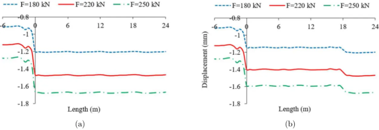
4.2 Investigating the Effect of Vehicle Load
In this section, the effect of vehicle load in the range of 180-250 kN on the behavior of the rail track at the transition zone with auxiliary rails is investigated. The diagrams of Figure 11 demonstrate the rail deflection variations for various vehicle loads in cases of presence and absence of the auxiliary rails. Moreover, the rail deflection variations in different track sections (slab track, transition zone with auxiliary rails and ballasted track) for different vehicle loads shown in Figure 12.
As seen in Figure 11(a), the maximum rail deflection from slab to ballasted tracks in the absence of auxiliary rails is suddenly increased, which is the same for all the vehicle loads and nearly 35%. Figure 11(b) shows the variations of the maximum rail deflection along the rail line in the case of transition zone with auxiliary rails for various vehicle loads. As seen in these figure, the increase in the rail deflection variations for various vehicle loads is on average 27% and 34% at the transition zone and in the ballasted track, respectively. Thus, the presence of the transition zone with auxiliary rails for vehicle loads of the range of 180-250 kN had an almost similar effect and led to the reduction in the intensity of rail deflection variations.
(a) (b)
Figure 11: Comparison of maximum rail deflection variations for 200 km/h speed and various vehicle loads along the track line: a) without transition zone, b) with transition zone include of auxiliary rails.
4.3 Investigating the Effect of Auxiliary Rails Number
One of the factors that can change track stiffness is the number of auxiliary rails. In this section, the transition zone is investigated with 2, 4, and 6 auxiliary rails. Figure 13shows the rail deflection variations along the track for different numbers of auxiliary rails. According to this figure, as expected, increasing the number of auxiliary rails, decreases the rail deflections in the transition zone. It should be noted however that, by adding 2 auxiliary rails, the track stiffness is very significantly increased, but by adding more auxiliary rails, the intensity of variations is reduced. Furthermore, it can be found that after adding 4 auxiliary rails, the effect of adding further auxiliary rail on the rail deflection variations became approximately insignificant.
Figure 13: Comparison of maximum rail deflection variations along the track line with various numbers of auxiliary rails (200 km/h speed and 180 kN vehicle load).
4.4 Investigating the Effect of Rail Pad Stiffness
In this section, the effect of railpad stiffness variations in the reasonable range of 40-250 kN/mm (Esmaeili and Heydari 2013) on the behavior of the transition zone with auxiliary rails is investigated. Figure 14 represents the maximum rail deflection variations along the rail line for various railpad stiffness in the cases of presence and absence of the auxiliary rails and Figure 15 shows the rail deflection variations in different track sections (slab track, transition zone with auxiliary rails and ballasted track) for various railpad stiffness values.
Figure 14(b) shows the maximum rail deflection variations for different railpad stiffness values in the case of using the auxiliary rails at the transition zone. As seen in this diagram, the presence of the auxiliary rails in tracks with railpad stiffness of 40, 180, and 250 kN/mm, causes an increase of rail deflections at the transition zone by 15%, 28%, and 30% respectively and increases up to 18%, 35%, and 38% respectively. Thus, it can be said that for the various cases of railpad stiffness, the use of auxiliary rails can lead to lower rail deflection variations along the track.
(a) (b)
Figure 14: Comparison of maximum rail dflection variations for various railpad stiffness along the track line: a) without transition zone, b) with transition zone include of auxiliary rails (200 km/h speed and 180 kN vehicle load).
Figure 15: Variations of rail deflection for various railpad stiffness in different track sections: slab track, transition zone with auxiliary rails, ballasted track (200 km/h speed and 180 kN vehicle load).
5 CONCLUSION
The use of two auxiliary rails leads to lower rail deflection variations from the slab to ballasted tracks for all analyzed speeds. The increase in rail deflections at the transition zone in the absence of the auxiliary rails was nearly 35% and 40% for low/medium speeds and high speeds, respectively, while with the use of the two auxiliary rails the rail deflection variation at the transition zone decreased to 28% and 33% for low/medium speeds and high speeds, respectively. The addition of more than two auxiliary rails further decreases the rail deflection variation
along the railway transition. However, the reduction is small, making the choice for more than two auxiliary rails less attractive.
The use of softer railpads along the transition segment of the track contributes for a smoother rail deflection variation. It this study it was seen that with auxiliary rails the rail deflection increase from the slab track to the transition zone was about 28% in case of stiff railpads, and only 12,5% in the case of soft railpads.
By studying the effect of using auxiliary rails in transitions from slab tracks to ballasted tracks under different loading conditions using a rather detailed 3D FEM train-track interaction model, it was again shown that numerical approaches can be valuable tools to designers and to rail infrastruc-ture managers in assessing and quantifying the influence of different design approaches to mitigate problems at railway transitions.
References
AREMA (2005). Portfolio of Trackwork Plans., American Railway Engineering and Maintenance-of-Way Association. Plan NO. 913-52.
Bathe, K. J. (1996). Finite Element Procedures. Prentice Hall, New Jersey, United States.
Bhatti, M. A. (2005). Fundamental Finite Element Analysis and Applications: with Mathematica and Matlab Com-putations. John Wiley & Sons, Inc, 1st edition, New Jersey, United States.
Christopher, D. Norman, (2004). Measurement of Track Modulus from a Moving Railcar. Master Thesis, University of Nebraska, Lincoln, United States.
Coelho, B., Priest, J., Holscher, P., Powrie, W. (2009). Monitoring of transition zones in railways. In M. Forde (Ed.), Railway engineering 2009. Engineering Technics Press.
Electro-Motive Diesel (EMD) (1967). United States, http://www.progressrail.com/.
Esmaeili, M., Heydari-Noghabi, H. (2013). Investigating Seismic Behavior of Ballasted Railway Track in Earthquake Excitation Using Finite-Element Model in Three-Dimensional Space. Journal of Transportation Engineering, 139 (7): 697-708.
Holscher, P., and Meijers, P. (2007). Literature study of knowledge and experience of transition zones. Technical report, GeoDelft.
Hughes, T.J.R. (2003). The Finite Element Method. Dover Publications Inc, New York, United States.
Hyslip, J. P., Li, D., McDaniel, C. R. (2009). Railway bridge transition case study. In E. Tutumluer and L. Al-Qadi (Eds.), Proceedings of the 8th International Conference Bearing Capacity of Roads, Railways and Airfields, CRC Press, 1341–1348.
Insa, R., Salvador, P., Inarejos, J., Roda, A. (2012). Analysis of the influence of under sleeper pads on the railway vehicle/track dynamic interaction in transition zone. Journal of Rail and Rapid Transit, 226 (4): 409-420.
Lei, X., Zhang, B. (2010). Influence of track stiffness distribution on vehicle and track interactions in track transition. Proceedings of the Institution of Mechanical Engineers, Part F: Journal of Rail and Rapid Transit, 224(6): 592-604. Li, D., Otter, D., Carr, G. (2010). Railway bridge approaches under heavy axle load traffic: problems, causes, and remedies. Proceedings of the Institution of Mechanical Engineers, Part F: Journal of Rail and Rapid Transit, 224 (5): 383– 390.
Lysmer, J., Kuhlemeyer, R.L. (1969). Finite dynamic model for infinite media. Journal of the Engineering Mechanics Division, 95(EM4): 859–877.
Metra Company (2009). Project reports (in Persian); Constructing of underground railway lines through urban area: geotechnical properties of soil layers and substructure characteristics. Metra Consulting Engineering Company. Metra Company (2009). Project reports (in Persian); Constructing project of underground railway lines through urban area: specification of superstructure system of railway track. Metra Consulting Engineering Company.
Plasser & Theurer Company. (2009). Austria, Wien, https://www.plassertheurer.com/.
Read, D., Li, D. (2006). Research results digest 79- Design of Track Transitions. Transportation Technology Center, Inc. (TTCI).
Real, J., Zamorano, C., Real, T., and Morales, S. (2016). New Transition Wedge Design Composed by Prefabricated Reinforced Concrete Slabs. Latin American Journal of Solids and Structures, 13: 1431-1449.
Ribes, F., Velarte, J., Perez, J., and Real, J. (2016). Study of Vibrations in a Short-Span Bridge Under Resonance Conditions Considering Train-Track Interaction. Latin American Journal of Solids and Structures, 13: 1236-1249. Sasaoka, C. D., Davies, D. (2005). Implementing track transition solutions for heavy axle load service. In AREMA 2005.
Shan, Y., Albers, B., Savidis, T. A. (2013). Influence of different transition zones on the dynamic response. Computers and Geotechnics, 48: 21-28.
Sussman, T.R., Selig, E.T. (1998). Track Component Contributions to Track Stiffness. E. T. Selig, Inc. Amherst, MA. TCRP (2000). Track Design Hand-book for Light Rail Transit. TCRP Report 57, Transportation Research Board, National Research Council, Washington, DC.
Timoshenko, S., Goodier, J. (1970). Theory of Elasticity. McGraw-Hill Higher Education, 3rd edition, ISBN 0070858055, New York, United States.
TML (2013). Tokyo Sokki Kenkyujo Company. Tokyo, Japan, http://www.tml.jp/.
Vale, C., Calçada, R., (2014). A Dynamic Vehicle-Track Interaction Model for Predicting the Track Degradation Process. Journal of Infrastructure Systems, 20 (3): 04014016-1-13.
Varandas, J.N., Hölscher, P., Silva, M.A.G. (2013). Settlement of ballasted track under traffic loading. Application to transition zones. Proceedings of the Institution of Mechanical Engineers, Part F: Journal of Rail and Rapid Transit, 228(3): 242-259.
Varandas, J.N., Hölscher, P., Silva, M.A.G. (2016). Three-dimensional track-ballast interaction model for the study of a culvert transition. Soil Dynamics and Earthquake Engineering, 89: 116-127.
Zakeri, J.A., Xia, H. (2008). Sensitivity analysis of track parameters on train-track dynamic interaction. Journal of Mechanical Science and Technology, 22 (7): 1299–1304.
Zakeri, J.A., Ghorbani, V. (2011). Investigation on dynamic behavior of railway track in transition zone. Journal of Mechanical Science and Technology, 25 (2): 287-292.
Zhai, W.M. (1996). Two simple fast integration methods for Large-Scale dynamic problems in engineering. Interna-tional Journal for Numerical Methods in Engineering, 39 (24): 4199–4214.
Zuada Coelho, B.E. (2010). Dynamics of railway transition zones in soft soils. PhD. Thesis, Delft University of Tech-nology.
Zuada Coelho, B.E., Hölscher, P., Priest, J., Powrie, W., Barends, F.B.J. (2010). An assessment of transition zone performance. Proc. IMechE Part F: J. Rail and Rapid Transit, 224: 1-11.