Abstract
A new fifth-order shear and normal deformation theory (FOSNDT) is developed for the static bending and elastic buckling analysis of functionally graded beams. The properties of functionally graded material are assumed to vary through the thickness direction according to power-law distribution (P-FGM). The most important feature of the present theory is that it includes the effects of transverse shear and normal deformations. Axial and transverse displacements involve polynomial shape functions to include the effects of transverse shear and normal deformations. A polynomial shape function expanded up to fifth-order in terms of the thickness coordinate is used to account for the effects of transverse shear and normal deformations. The kinematics of the present theory is based on six independent field variables. The theory satisfies the traction free boundary conditions at top and bottom surfaces of the beam without using problem dependent shear correction factor. The closed-form solutions of simply supported FG beams are obtained using Navier’s solution procedure and non-dimensional results are compared with those obtained by using classical beam theory, first order shear deformation theory and other higher order shear deformation theories. It is concluded that the present theory is accurate and efficient in predicting the bending and buckling responses of functionally graded beams.
Keywords
Functionally graded beam, transverse shear deformation, transverse normal deformation, bending, buckling.
A New Fifth-Order Shear and Normal Deformation Theory
for Static Bending and Elastic Buckling of P-FGM Beams
1 INTRODUCTION
Today great emphasis is being placed on developing new materials or material systems tailored for specific applications. Currently the main focus of the researcher is to develop new composite
S. M. Ghumare a, * A. S. Sayyad b
a Research Scholar, Department of Civil Engineering, SRES’s Sanjivani College of Engineering, Savitribai Phule Pune University, Kopargaon-423603, Maharashtra, India.
E-mail: [email protected] b Professor, Department of Civil
Engineering, SRES’s Sanjivani College of Engineering, Savitribai Phule Pune University, Kopargaon-423603, Maharashtra, India.
E-mail: [email protected]
* Corresponding author
http://dx.doi.org/10.1590/1679-78253972
materials due to enormous benefits like improvements in material performance, ability to support optimized structural designs, continued lowering of manufacturing costs, and the ability to perform reliably in service. The traditional composite material is incapable to employ under the high-temperature environments and may fail due to delamination or stress concentration. A functionally graded material (FGM) is a novel class of material having unique characteristics and can be used alternatively to overcome the delamination failure that usually occurs in laminated composites. FGM have received major attention as a heat-shielding advanced structural material in various engineering applications like automobile, aircraft, aerospace projects and defense industry.Functionally graded materials (FGMs) are those in which the volume fraction of two or more materials is varied continuously as a function of position along certain directions of the structure (normally in thickness direction). The FG materials are generally ceramic and metal constituents. The ceramic constituent provides high-temperature resistance due to its low thermal conductivity; whereas the ductile metal constituent prevents fracture caused by stresses due to the high temperature gradient in a very short span of time and provides stronger mechanical performance.
Functionally graded material is the first time developed in 1984 by a group of material scientists in Japan during a space plane project in the form of thermal barrier material which can withstand a huge temperature fluctuation across a very thin cross-section. Development in FG material and its applications can be found in the literature by Koizumi (1993, 1997), Muller et al. (2003) and Birman and Byrd (2006, 2007). Rasheedat et al. (2012) discussed the various processing techniques and interdisciplinary applications of FGM. The more information on beams and plates made of FGM is found in Jha et al. (2013) and Swaminathan et al. (2014).
The well-known elasticity solution for simply supported functionally gradient beams subjected to sinusoidal loading was developed by Sankar (2001). Material properties are assumed to vary according to an exponential law. Further, few more researchers have presented research on elasticity solutions for functionally graded beams Zhong and Yu (2007), Daouadji et al. (2013), Chu et al. (2015). 2D elasticity solutions for thick functionally graded beams are analytically very difficult and computationally cumbersome. Therefore, several analytical and numerical methods have been proposed by researchers to analyze the FG beams accurately using approximate lower and higher order shear deformation theories.
Reddy (1984) developed well known third order parabolic shear deformation theory for the analysis of composite beams, plates and shells. Benatta et al. (2008) presented a static analysis of functionally graded shear deformable beams considering three point bending. Li et al. (2010) developed the higher order shear deformation theory for bending of functionally graded beams and proved that the displacements and stresses are depend on the gradient variation of material properties. Pendhari et al. (2010) developed a simple mixed semi analytical model for 2D stress analysis of functionally graded beams subjected to transverse load and compared the results with those obtained by using Navier’s closed form solution. Giunta et al. (2010, 2011) proposed several higher order refined theories based on the Carrera’s unified formulation for the analysis of functionally graded beams. Thai and Vo (2012) studied static bending and free vibration of functionally graded beams based on various higher-order shear deformation beam theories and Navier’s solution technique.Li and Batra (2013) applied CBT and FSDT for the buckling analysis of functionally graded beams of various boundary conditions. Nguyen et al. (2013) presented bending and free vibration of functionally graded beams using FSDT. Vo et al. (2014) presented static and free vibration analysis of functionally graded beams using refined shear deformation theory. Bourada et al. (2015) developed a new trigonometric shear and normal deformation theory for bending and free vibration of functionally graded beams. Simsek (2016) presented buckling of bi-directional functionally graded Timoshenko beams with different boundary conditions using Ritz method. Recently, Sayyad and Ghugal (2017b) developed a unified shear deformation theory for bending of functionally graded plates and beams and obtained closed form solutions using Navier’s solution technique.
In the present study, a fifth-order shear and normal deformation theory is developed for the bending and buckling analysis of functionally graded beams subjected to transverse and axial loadings. The most important feature of the present theory is that it includes for the effects of transverse shear and normal deformations. A polynomial shape function expanded up to fifth-order in terms of the thickness coordinate is used to account the effects of transverse shear and normal deformations. The kinematics of the present theory are based on six independent field variables. The theory satisfies the traction free boundary conditions at top and bottom surfaces of the beam without using problem dependent shear correction factor. The closed-form solutions of simply supported FG beams are obtained using Navier’s solution procedure and non-dimensional results are compared with those obtained by using classical beam theory, first order shear deformation theory and other higher order shear deformation theories.
2 FORMULATION OF THE PRESENT THEORY
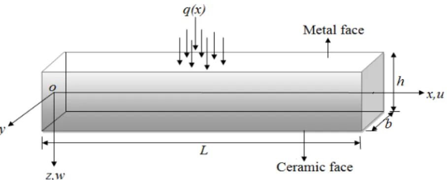
Figure 1: Geometry and coordinates of P-FGM beam under consideration
2.1 Novelty of the Present Theory
The transverse shear and normal deformations play an important role in predicting the accurate structural behaviour of beams and plates made of advanced composite materials. Therefore, any refinements of classical beam theories are generally meaningless, unless the effects of transverse shear and normal strains are both taken into account. This is also discussed by Carrera (2005) and Carrera et al. (2011). In the view of this, the present theory is having following important features.
1)The most important feature of the present theory is that it includes the effects of transverse shear and normal deformations.
2)The axial displacement in the x direction consists of extension, bending and shear components. The axial displacement is expressed in terms of polynomial shape function expanded up to the fifth-order in terms of the thickness coordinate.
3)The transverse displacement is a function of both x and z coordinates. Hence the theory is designated as the fifth-order shear and normal deformation theory.
4)The theory contains six independent unknown variables.
5)The theory enforces the parabolic variation of the transverse shear stress across the thickness of the beam. Thus, the theory obviates the need for the shear correction factor.
2.2 Kinematics
Based on the above features, the displacement field of the present theory is as follows:
2 4
0
0 2 4
2 4
0 2 4
4 16
, 1 1
3 5
, 1 4 1 16
x x
z z
dw z z
u x z u x z z x z x
dx h h
z z
w x z w x x x
h h
(1)
with the transverse shear deformation whereas
z and
z are the shear slopes associated with the transverse normal deformations. Third order and fifth-order polynomial functions are assigned according to the shearing stress distribution through the thickness of the beam in such a way that shear stress vanishes at top and bottom surfaces of the beam.The nonzero strain components associated with the present theory are obtained using linear theory of elasticity.
1
20 1 2
1 2
'' ''
1 2
' '
1 2
( ) ( )
b
x x x x x
z z z
s s
xz xz xz
zk f z f z
f z f z
f z f z
(2)
where
1 2
2
0 0 0 1 2
2
2 4 2 4
' '
1 2 2 4 1 2 2 4
3 " "
1 2 2 4
, , , , , ,
4 16
1 , 1 , 1 4 , 1 16
3 5
8 , 64
s s
b x x z z
x x x x xz x xz x
u w
k
x x x x x x
z z z z
f z z f z z f z f z
h h h h
z z
f z f z z
h h
(3)
2.3 Material Gradation and Constitutive Relation
The properties of functionally graded materials vary continuously due to gradually change in the volume fraction of the constituent materials. In the present study, the material properties of FG beam are assumed to vary continuously through the thickness of the beam according to a power law distribution.
m
c m
1
2
Pz
E z
E
E
E
h
(4)100 200 300 400 E(Z) -0.5 -0.25 0 0.25 0.5 z/h
P=Power Law Index P=0.1 P=0.2 P=0.5 P=1 P=2 P=5 P=10 P=0(Ceramic) P=etal
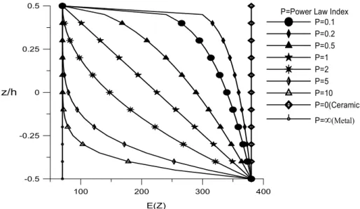
Figure 2: Variation of Young’s modulus through the thickness of a P-FGM beam for various values of the power law index.
The linear constitutive relations at a point of the functionally graded beam can be written as
11 13 13 33 550
0
0
0
x x z z xz xzQ
z
Q
z
Q
z
Q
z
Q
z
(5) Where
11 33 1 ( )2, 13 1 ( )2 , 55 2(1( ))
E z E z E z
Q z Q z Q z
Q z
(6)
2.4 Governing Differential Equations
The six variationally consistent governing differential equations of the present theory are obtained using the principle of virtual displacements.
/2
0 0
0 0
0 /2 0
L h L
x x z z xz xz
h
dw d w
dz dx q x w N dx
dx dx
(7)where the symbol
denotes the variational operator. Substituting strains from Eq. (2) into the Eq. (7) one can write
1 2 1 2
2
1
0 0
2 0
1 2 2 0 0
0 0
0
L
S S S S
b x x
x x x x z z z z xz x
L
z z
xz xz x xz
d u d w d d
N M M M Q Q Q
dx dx dx dx
dw d w
d d
Q Q Q dx q x w N dx
dx dx dx dx
where
1 2 1 2 /2 1 2 /2 /21 2 ' '
1 2 /2 /2 " " 1 2 /2
, , , 1, , , ,
, , ,
, ,
h
S S
b
x x x x x
h h
xz xz xz
h
h
S S
z z z
h
N M M M z f z f z dz
Q Q f z f z dz
Q Q f z f z dz
(9)where Nxis the resultant axial force, b X
M is the resultant moment due to bending, S1
X
M and S2
X
M are the resultant moment due to shear deformation and Q1xz,
2
xz
Q , S1, S2
z z
Q Q are the resultant shear forces. Integrating Eq. (8) by parts and setting the coefficients of u , w ,0 0 x, x, z, zequals
to zero, the following governing differential equations are obtained
1 2
1 2
2 2
0
0 0 2 0 2
1 2
1 2
: 0, : 0,
: 0, : 0,
: 0, : 0
b
x x
S S
x x
x xz x xz
S S
xz xz
z z z z
dN d M d w
u w q N
dx dx dx
dM dM Q Q dx dx dQ dQ Q Q dx dx (10)
The boundary conditions obtained atx0 and xLare of the following form
Either Nx 0 or u0is prescribed (11)
Either b 0 x
M or dw0
dx is prescribed (12)
Either 0
b x
dM
dx or wbis prescribed (13)
Either S1 0
x
M or xis prescribed (14)
Either S2 0
x
M or xis prescribed (15)
Either Q1xz0 or zis prescribed (16)
Either Qxz2 0 or zis prescribed (17)
Substitution of stress resultants from Eq. (9) into Eq. (10) leads to the following form of governing differential equations in-terms of unknown displacement variables.
2 3 2 2
0 0
0: 11 2 11 3 11 2x 11 2x 13 z 13 z 0
d u d w d d d d
u A B C D F H
dx dx dx dx dx dx
3 4 3 3 2 2 2
0 0 0
0: 11 2 S11 4 S11 3x S11 3x S13 2Z S13 2Z 0 2
d u d w d d d d d w
w B A C D F H q N
dx dx dx dx dx dx dx
(19)
2 3 2 2
0 0
11 2 11 3 111 2 211 2 13 13
155 55
:
0
x x Z Z
x S SS SS SS SS
x x
SS x SSS x
d u d w d d d d
C C C C F H
dx dx dx dx dx dx
d d F H dx dx
(20)2 3 2 2
0 0
11 2 11 3 211 2 211 2 13 13
55 255
:
0
x x Z Z
x S SS SS SSS SSS
z z
SSS x SS x
d u d w d d d d
D D C D F H
dx dx dx dx dx dx
d H F x dx
(21) 2 0 013 13 2 13 13 133 233
2 2
155 2 55 2
:
0
x x
z S SS SSS SSS Z SSS z
x z x z
SS SSS
du d w d d
F F F F F F
dx dx dx dx
d d d d
F H
dx dx dx dx
(22) 2 0 013 13 2 13 13 233 233
2 2
55 2 255 2
:
0
x x
z S SS SSS SSS Z SSS z
x z x z
SSS SS
du d w d d
H H H H F H
dx dx dx dx
d d d d
H F
dx dx dx dx
(23) Where
/2 1 2 /2/2 '' ''
1 2 1 2
/2
/2
1 2 /2 1 1 2
/2 2
2 /2 2
, , , 1, , , ,
, , , , , , , ( ), ( ) ,
, ( ) ( ), ( ) ,
,
h
ij ij ij ij h ij
h
Sij S ij Sij Sij Sij h ij
h
SS ij SS ij h ij
h
SS ij h ij
A B C D Q z z f z f z dz
A C D F H Q z z z f z f z f z f z dz
C C Q z f z f z f z dz
D Q z f z dz F
/2 " /2 "
1 2
/2 /2
/2 '' ''
1 1 2
/2
/2 ' ' '
2 /2 2 1 2
/2 '' ''
2 1 2
/2 , , , ( ), , , , ( ) , , , ( ) h h
ij h ij ij h ij
h
SS ij SS ij h ij
h
SSS ij SS ij h ij
h
SS Sij SSS ij h ij
Q z f z dz H Q z f z dz
F H Q z f z f z f z dz
H F Q z f z f z f z dz
F H Q z f z f z f z dz
/2 ' ' /2 '' ''
1 /2 1 1 1 /2 1 1
/2 " " "
2 2 /2 2 1 2
, ,
, , ,
h h
SS ij h ij SSS ij h ij
h
SSS ij SSS ij h ij
F Q z f z f z dz F Q z f z f z dz
F H Q z f z f z f z dz
2.5 Analytical Solutions
A functionally graded beam simply supported at its edges
x
0
andx
L
is considered for the analytical solutions. Analytical solution for the bending analysis of simply supported functionally graded beams is obtained using Navier’s solution technique. According to Navier’s technique, the displacement variables are expanded into a single trigonometric series.0 0
1 1 1
1 1 1
cos , sin , cos ,
cos , sin , sin
m m x x m
m m m
x xm z zm z zm
m m m
u u x w w x x
x x x
(25)whereum,wm, xm, xm, zm, zmare unknown coefficients and
m
/L. The transverse load q(x)acting on the top surface of the beam is also expanded in a single trigonometric series.
1 msin
m
q x q
x
(26)Where
0 0 Sinusoidal load4 Uniformly distributed load
m m q q q q m
(27)Substituting the trigonometric form of u w0, , , , ,0 x x z z and q x( )from Eqs. (25)-(27) into
governing equations (18)-(23), the analytical solutions can be obtained from the following equation.
K
f (28)where [K] is the stiffness matrix,
f is the force vector and
is the vector of unknowns coefficients. The elements of the
K ,
and
f are as follows,2 3 2 2
11 11 12 11 13 11 14 11 15 13 16 13
3 4 3 3 2 2
21 11 22 11 23 11 24 11 25 13 26 13
2 3 2 2
31 11 32 11 33 111 155 34 211 55
35
, , , , , ,
, , , , ,
, , ( ), ( ),
S S S S S
S SS SS SS SSS
K A K B K C K D K F K H
K B K A K C K D K F K H
K C K C K C F K C H
K
2 3
13 155 36 13 55 41 11 42 11
2 2
43 211 55 44 211 255 45 13 55
2
46 13 255 51 13 52 13 53 13 155
( ) , ( ) , , ,
( ), ( ), ( ) ,
( ) , , , ( ) ,
SS SS SS SSS S
SS SSS SS SS SSS SSS
SSS SS S SS SS
F F K H H K D K D
K C H K D F K F H
K H F K F K F K F F
2
54 13 55 55 155 133
2 2
56 155 233 61 13 62 13 63 13 55
2 2
64 13 255 65 55 233 66 255 233
( ) , ( ),
( ), , , ( ) ,
( ) , ( ), ( )
, , , , ,
SSS SSS SS SSS
SSS SSS S SS SSS
SSS SS SSS SSS SS SSS
m m xm xm zm
K F H K F F
K H F K H K H K H H
K H F K H F K F H
u w
T and
0 0 0 0 0
Tzm f qm
3 NUMERICAL RESULTS AND DISCUSSION
In the section static bending and elastic buckling problems are presented and discussed to verify the accuracy of the present theory. For numerical results, the P-FGM beam made of metal (Aluminum:
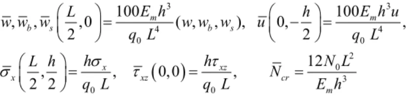
Em= 70 GPa and μm= 0.3) and ceramic (Alumina: Ec= 380GPa, μc= 0.3) is considered. The material properties of P-FGM beam varying continuously in the thickness direction according to the power-law distribution. Displacements and stresses are presented in the following non-dimensional form
3 3
4 4
0 0
2 0
3
0 0
100 100
, , ,0 ( , , ), 0, ,
2 2
12
, , 0,0 ,
2 2
m m
b s b s
x xz
x xz cr
m
E h E h u
L h
w w w w w w u
q L q L
h h N L
L h
N
q L q L E h
(30)
3.1 Bending of P-FGM Beam
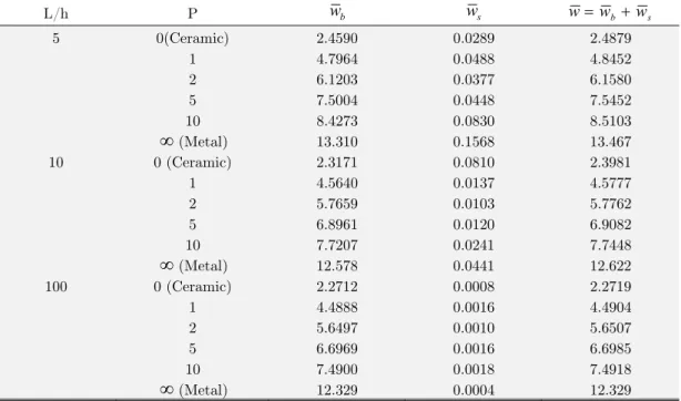
Table 1 shows non-dimensional bending (wb) and shear components (ws) of transverse
displacement (w) for FG beams subjected to a sinusoidal load. The numerical results are obtained for various values of the power law index and aspect ratios. From Table 1 it reveals that shear component of transverse displacement is decreases with increase in aspect ratio. This is in fact due to, shear deformation is more pronounced in thick beams than the slender beams. Also, the transverse displacement is increases with an increase in power law index which is due to decrease in stiffness of the beam.
compressive in nature when the beam is of fully metal and tensile when it is of fully ceramic. The variation of axial stress is non-linear through the thickness for P = 1, 5, 10 and linear for P = 0 and ∞. It is also pointed out that the axial stresses in metal and ceramic beams are identical. The Fig. 6 shows through the thickness distribution of transverse shear stress, which is zero at top and bottom surfaces, but not maximum at the center of the cross-section due to continuous variation of material properties through the thickness of the beam.
L/h P wb ws wwb ws
5 0(Ceramic) 2.4590 0.0289 2.4879
1 4.7964 0.0488 4.8452
2 6.1203 0.0377 6.1580
5 7.5004 0.0448 7.5452
10 8.4273 0.0830 8.5103
(Metal) 13.310 0.1568 13.46710 0 (Ceramic) 2.3171 0.0810 2.3981
1 4.5640 0.0137 4.5777
2 5.7659 0.0103 5.7762
5 6.8961 0.0120 6.9082
10 7.7207 0.0241 7.7448
(Metal) 12.578 0.0441 12.622100 0 (Ceramic) 2.2712 0.0008 2.2719
1 4.4888 0.0016 4.4904
2 5.6497 0.0010 5.6507
5 6.6969 0.0016 6.6985
10 7.4900 0.0018 7.4918
(Metal) 12.329 0.0004 12.329Table 1: Non–dimensional bending and shear components of transverse displacement of P-FGM beams subjected to sinusoidal load.
-4 -2 0 2 4
-0.5 -0.25 0 0.25 0.5
z/h
P=Power Law Index P=0 (Ceramic) P=1 P=5 P=10 P=
Metal)P Theory Model u (-h/2)
w
(0)
x (h/2)
xz
(0) 0 (Ceramic) Present (z0) FOSNDT 0.7202 2.4808 3.0999 0.5474
Reddy (1984) (z0) PSDT 0.7251 2.5020 3.0916 0.4769 Sayyad and Ghugal (2017b) (z0) TSDT 0.7259 2.5016 3.0949 0.4920 Sayyad and Ghugal (2017b) (z0) HSDT 0.7247 2.5003 3.0899 0.4739 Sayyad and Ghugal (2017b) (z0) ESDT 0.7280 2.4974 3.1039 0.4871 Timoshenko (1921) (z0) FSDT 0.7129 2.5023 3.0396 0.3183 Bernoulli-Euler (z0) CBT 0.7129 2.2693 3.0396 ---
1 Present (z0) FOSNDT 1.7131 4.8452 4.7667 0.5225
Reddy [1984] (z0) PSDT 1.7793 4.9458 4.7856 0.5243 Sayyad and Ghugal (2017b) (z0) TSDT 1.7806 4.9451 4.7912 0.5331 Sayyad and Ghugal (2017b) (z0) HSDT 1.7517 4.9257 4.7165 0.6025 Sayyad and Ghugal (2017b) (z0) ESDT 1.7819 4.9432 4.7964 0.5430 Timoshenko (1921) (z0) FSDT 1.7588 4.8807 4.6979 0.5376 Bernoulli-Euler (z0) CBT 1.7588 4.5528 4.6979 ---
5 Present (z0) Present 2.7339 7.5452 6.3352 0.5026
Reddy (1984) (z0) PSDT 2.8644 7.7723 6.6057 0.5314 Sayyad and Ghugal (2017b) (z0) TSDT 2.8671 7.7792 6.6172 0.5144 Sayyad and Ghugal (2017b) (z0) HSDT 2.8641 7.7715 6.6047 0.5332 Sayyad and Ghugal (2017b) (z0) ESDT 2.8697 7.7830 6.6281 0.5022 Timoshenko (1921) (z0) FSDT 2.8250 7.5056 6.4382 0.9942 Bernoulli-Euler (z0) CBT 2.8250 6.8994 6.4382 ---
10 Present (z0) FOSNDT 2.8969 8.5103 7.8979 0.4431
Reddy (1984) (z0) PSDT 2.9989 8.6530 7.9080 0.4226 Sayyad and Ghugal (2017b) (z0) TSDT 3.0022 8.6561 7.9195 0.4392 Sayyad and Ghugal (2017b) (z0) HSDT 2.9986 8.6527 7.9070 0.4211 Sayyad and Ghugal (2017b) (z0) ESDT 3.0054 8.6547 7.9301 0.4558 Timoshenko (1921) (z0) FSDT 2.9488 8.3259 7.7189 1.2320 Bernoulli-Euler (z0) CBT 2.9488 7.5746 7.7189 ---
(Metal) Present(z0) FOSNDT 3.9097 13.505 3.0999 0.5474Reddy (1984) (z0) PSDT 3.9363 13.582 3.0916 0.4769
Sayyad and Ghugal (2017b)(z0) ESDT 3.9444 13.574 3.0980 0.5072
Timoshenko (1921) (z0) FSDT 3.8702 12.552 3.0396 0.3183
Bernoulli-Euler (z0) CBT 3.8702 12.319 3.0396 ----
0 20 40 60 80 100
L / h 0
2 4 6 8 10 12 14 16 18
20 P=Power Law Index
P=0 (Ceramic) P= 1 P= 5 P=10 P= etal)
Figure 4: Variation of non-dimensional transverse displacement (w) of simply supported P-FGM beam subjected to sinusoidal load using various aspect ratios.
-4 -2 0 2 4 6 8
-0.5 -0.25 0 0.25 0.5
z/h
P=Power Law Index P=0 (Ceramic) P= 1 P=5 P=10 P=
Metal)Figure 5: Through thickness variation of non-dimensional bending stress (x) of
simply supported P-FGM beam subjected to sinusoidal load (L/h=5).
0 0.2 0.4 0.6
-0.5 -0.25 0 0.25 0.5
z/h
P=Power Law Index P=0 (Ceramic) P=1 P=5 P=10 P=Metal)
Figure 6: Through thickness variation of non-dimensional transverse shear stress (xz ) of
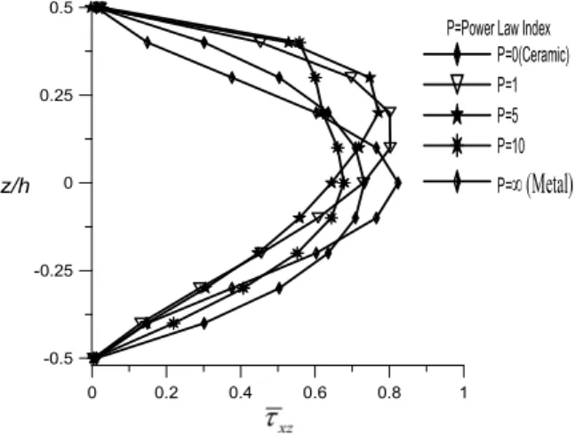
Comparison of maximum non-dimensional displacements and stresses of FG beam subjected to a uniformly distributed load for various values of the power law index is presented in Table 3. The present results are compared with those obtained by using other higher order theories. It is observed that displacements and stresses are increased with an increase in power law index. This is due to the fact that an increase of the power law index increases the flexibility of FG beam. Displacements and stresses predicted by using the present theory are in excellent agreement with those obtained by using other higher order beam theories. Through thickness distributions of axial displacement, bending stress and transverse shear stress are plotted in Figures 7, 9 and 10 respectively, whereas variation of transverse displacement with respect to L/h ratio is shown in Fig. 8.
-8 -4 0 4 8
-0.5 -0.25 0 0.25 0.5
z/h
P=Power Law Index P=0 (Ceramic) P=1 P=5 P=10 P=etal
Figure 7: Through thickness variation of non-dimensional axial displacement (u) of simply supported P-FGM beam subjected to uniformly distributed load (L/h=5).
0 20 40 60 80 100 L/h
0 5 10 15 20
25 P=Power Law Index
P=0 (Ceramic) P=1 P=5 P=10 P=
etalP Theory Model u (-h/2)
w
(0)
x (h/2)
xz
(0) 0 (Ceramic) Present (z0) FOSNDT 0.9260 3.1395 3.7931 0.7325
Reddy (1984) (z0) PSDT 0.9397 3.1654 3.8028 0.7305
Sayyad and Ghugal (2017b)(z0) TSDT 0.9409 3.1649 3.8061 0.7524 Sayyad and Ghugal (2017b) (z0) HSDT 0.9391 3.1633 3.8010 0.7246
Sayyad and Ghugal (2017b)(z0) ESDT 0.9441 3.1598 3.8152 0.7438
Timoshenko (1921) (z0) FSDT 0.9210 3.1657 3.7501 0.4922
Bernoulli-Euler (z0) CBT 0.9210 2.8783 3.7501 ----
1 Present (z0) FOSNDT 2.2161 6.1335 5.8674 0.8024
Reddy (1984) (z0) PSDT 2.3037 6.2594 5.8850 0.8031
Sayyad and Ghugal (2017b)(z0) TSDT 2.3036 6.2586 5.8906 0.8152
Sayyad and Ghugal (2017b) (z0) HSDT 2.2618 6.2361 5.8150 0.8811
Sayyad and Ghugal (2017b)(z0) ESDT 2.3074 6.2563 5.8958 0.8288
Timoshenko (1921) (z0) FSDT 2.2722 6.1790 5.7960 0.8313
Bernoulli-Euler (z0) CBT 2.2722 5.7746 5.7960 ----
5 Present (z0) Present 3.5388 9.5411 7.7638 0.7709
Reddy (1984) (z0) PSDT 3.7098 9.8281 8.1127 0.8114 Sayyad and Ghugal (2017b)(z0) TSDT 3.7138 9.8367 8.1242 0.7836
Sayyad and Ghugal (2017b) (z0) HSDT 3.7095 9.8271 8.1117 0.8144
Sayyad and Ghugal (2017b)(z0) ESDT 3.7176 9.8414 8.1351 0.7633
Timoshenko (1921) (z0) FSDT 3.6496 9.4987 7.9430 1.5373
Bernoulli-Euler (z0) CBT 3.6496 8.7508 7.9430 ----
10 Present (z0) FOSNDT 3.7514 10.760 9.7170 0.6596
Reddy (1984) (z0) PSDT 3.8861 10.938 9.7146 0.6451
Sayyad and Ghugal (2017b)(z0) TSDT 3.8910 10.942 9.7261 0.6691
Sayyad and Ghugal (2017b) (z0) HSDT 3.8857 10.937 9.7137 0.6432 Sayyad and Ghugal (2017b)(z0) ESDT 3.8956 10.940 9.7367 0.6929
Timoshenko (1921) (z0) FSDT 3.8096 10.534 9.5231 1.9050
Bernoulli-Euler (z0) CBT 1.8096 9.6072 9.5231 ----
(Metal) Present(z0) FOSNDT 5.0210 17.110 3.7984 0.8232Reddy (1984) (z0) PSDT 5.1012 17.183 3.8028 0.7305
Sayyad and Ghugal (2017b)(z0) ESDT 5.1133 17.173 3.8084 0.7741 Timoshenko (1921) (z0) FSDT 5.0000 15.912 3.7501 0.4922
Bernoulli-Euler (z0) CBT 5.0000 15.625 3.7501 ---
-4 0 4 8 12 -0.5
-0.25 0 0.25 0.5
z/h
P=Power Law Index P=0 (Ceramic) P=1 P=5 P=10 P=
etalFigure 9: Through thickness variation of non-dimensional bending stress (x) of simply
supported functionally graded beam subjected to uniformly distributed load (L/h=5).
0 0.2 0.4 0.6 0.8 1 -0.5
-0.25 0 0.25 0.5
z/h
P=Power Law Index P=0(Ceramic) P=1 P=5 P=10 P=etal
Figure 10: Through thickness variation of non-dimensional transverse shear stress (xz ) of simply
supported functionally graded beam subjected to uniformly distributed load (L/h=5).
3.2 Buckling of P-FGM beam
Power law index
L/h Theory Model 0(Ceramic) 1 2 5 10
(Metal)5 Present (z0) FOSNDT 49.4448 25.3494 19.8659 16.2105 14.4279 9.1082
Li and Batra (2013) PSDT 48.8350 24.6870 19.2450 16.0240 14.4270 ---- Nguyen et al.(2013) FSDT 48.8350 24.6870 19.2450 16.0240 14.4270 ---- Vo et al.(2014) HSDT 48.8372 24.6898 19.2479 16.0263 14.4286 ---- Vo et al. (2014) FSDT 48.8401 24.6911 19.1605 15.7400 14.1468 ---- 10 Present (z0) FOSNDT 52.4734 26.6399 21.0870 17.6309 15.7480 9.6662
Li and Batra (2013) PSDT 52.3090 26.1710 20.4160 17.1920 15.6120 ---- Nguyen et al.(2013) FSDT 52.3090 26.1710 20.4160 17.1940 15.6120 ---- Vo et al.(2014) HSDT 52.3085 26.1728 20.4187 17.1959 15.6134 ---- Vo et al (2014) FSDT 52.3082 26.1727 20.3963 17.1118 15.5291 ----
Table 4: Comparison of Non-dimensional critical buckling load (Fcr) o simply supported P-FGM beams with various values of power law index (P).
0 2 4 6 8 10
Power Law Index (P)
10 20 30 40 50 60
L / h = 5 L / h = 10
Figure 11: The variation of non-dimensional critical buckling load with respect to the power law index for simply supported P-FGM beam.
4 CONCLUSIONS
1)Since shear deformation is more pronounced in thick beam, shear component of transverse displacement decreases with increase in aspect ratio.
2)An Increase in the power law index decreases the stiffness of the beam. Therefore, displacements are increased with an increase in the power law index.
3)The variation of axial stress is non-linear through the thickness for P = 1, 5, 10 and linear for
P = 0 and ∞. Axial stress is compressive in nature when the beam is of fully metal and tensile when it is of fully ceramic.
4)The transverse shear stress is not maximum at the center of the cross-section due to continuous variation of material properties through the thickness of the beam.
5)From the buckling response of the functionally graded beam, it is observed that the critical buckling load decreases with an increase in power law index and increases with increase in
L/h ratio.
References
Benatta, M. A., Mechab, I., Tounsi, A., Bedia, E. A. A. (2008). Static analysis of functionally graded short beams including warping and shear deformation effects. Computational Material Science 44:765–773.
Birman, V., and Byrd, L.W. (2006). Functionally graded stitched laminates: illustration on the example of a double cantilever beam. ASCE Journal of Aerospace Enginering19:217-226.
Birman, V., and Byrd, L.W. (2007). Modeling and analysis offunctionally graded materials and structures. ASME Applied Mechanics Review 60:195-216.
Bourada M., Kaci A., Houari M. S. A., and Tounsi A. (2015). A new simple shear and normal deformations theory for functionally graded beams. Steel and Composite Structures 18:409-423.
Carrera, E. (2005). Transverse normal strain effects on termal stress analysis of homogeneous and layered plates. AIAA Journal 43(10):2232-2242.
Carrera, E., Giunta, G., and Petrolo, M. (2011). Beam Structures: Classical and Advanced TheoriesJohn Wiley & Sons Ltd U.K.
Chu, P., Li, X. F., Wu, J. X., Lee, K. Y. (2015). Two-dimensional elasticity solution of elastic strips and beams made of functionally graded materials under tension and bending. Acta Meccanica226:2235–2253.
Daouadji, T. H., Henni, A.H.,Tounsi, A, Bedia E. A. A. (2013). Elasticity solution of a cantilever functionally graded beam. Applied Composite Material 20:1–15.
Giunta, G., Belouettar, S., and Carrera, E. (2010). Analysis of FGM beams by means of classical and advanced theories. Mechanics of Advanced Materials and Structures 17(8):622-635.
Giunta, G., Crisafulli, D., Belouettar, S., Carrera, E. (2011). Hierarchical theories for the free vibration analysis of functionally graded beams. Composite Structures 94(1):68-74.
Jha, D. K., Kant, T., and Singh, R. K. (2013). A critical review of recent research on functionally graded plates. Composite Structures 96:833–849.
Koizumi, M. (1993). The concept of FGM. Ceramic Transactions. Functionally Gradient Materials 34:3-10. Koizumi, M. (1997). FGM activities in Japan. Composite Part B 28:1–4.
Li, S.R., and Batra, R.C. (2013). Relations between buckling loads of functionally graded Timoshenko and homogeneous Euler–Bernoulli beams. Composite Structures 95:5–9.
Muller, E., Drasar, C., Schilz, J., Kaysser, W. A. (2003). Functionally graded materials for sensor and energy applications. Material Science and Engineering A362:17–39.
Nguyen, T.K., Vo, T.P., Thai, H.T. (2013). Static and free vibration of axially loaded functionally gradedbeams based on the first-order shear deformation theory. Composite Part B 55:147–157.
Pendhari, S. S., Kant, T., Desai, Y. M., Subbaiah, C. V. (2010). On deformation of functionally graded narrow beams under transverse loads. International Journal of Mechanics and Material Design 6:269–282.
Rasheedat, M. M., Esther, T. A., Muku, S., and Sisa, P. (2012). Functionally Graded Material: An Overview. Procedding of World Congress on Engineering3:1-5.
Reddy, J.N. (1984).A simple higher order theory for laminated composite plates. ASME Journal of Applied Mechanics51:745-752.
Sankar, B. V. (2001).An elasticity solution for functionally graded beams. Composite Scienceand Technology 61:689– 696.
Sayyad, A. S., and Ghugal, Y. M. (2015). On the free vibration analysis of laminated composite and sandwich plates: A review of recent literature with some numerical results. Composite Structures 129:177–201.
Sayyad, A. S., and Ghugal, Y. M. (2017a). Bending, buckling and free vibration of laminated composite and sandwich beams: A critical rivew of literature. Composite Structures 171:486–504.
Sayyad, A. S., and Ghugal, Y. M. (2017b). A unified shear deformation theory for the bending of isotropic, functionally graded, laminated and sandwich beams and plates. International Journal of Applied Mechanics 9(1): 1-36.
Simsek, M. (2016). Buckling of Timoshenko beams composed of two-dimensional functionally graded material 2D-FGM having different boundary conditions. Composite Structures149:304-331.
Swaminathan, K., Naveenkumar, D. T., Zenkour, A. M., and Carrera E. (2014). Stress, vibration and buckling analyses of FGM plates-A state-of-the-art review. Composite Structures 120:10-31.
Thai, H. T., and Vo, T. P. (2012). Bending and free vibration of functionally graded beams using various higher-order shear deformation beam theories. International Journal of Mechanical Sciences 62:57–66.
Timoshenko, S. P. (1921). On the correction for shear of the differential equation for the transverse vibration of prismatic bars. Philosophical Magazine 41:742-746.
Vo, T.P., Thai, H.T., Nguyen, T.K., Inam, F. (2014). Static and vibration analysis of functionally graded beams using refined shear deformation theory. Meccanica 49:155–168.