*e-mail: [email protected]
Fabrication and Characterization of Nanofibrous Scaffold
Developed by Electrospinning
Brahatheeswaran Dhandayuthapani, Yasuhiko Yoshida, Toru Maekawa, D. Sakthi Kumar*
Bio Nano Electronics Research Centre, Graduate School of Interdisciplinary New Science,
Toyo University, Kawagoe, Saitama, Japan
Received: October 29, 2010; Revised: June 17, 2011
Electrospinning has been recognized as an efficient technique for the forming of polymer nanofibers. Silk fibroin (SF) nanofibers were electrospun from SF solution using trifluoroacetic acid solution as a solvent. In the present work, we have systematically evaluated the effects of instrument parameters, including applied voltage, tip-target distance, solution flow rate, solution parameters; such as polymer concentration and solution viscosity on the morphology of electrospun SF fibers. The applied voltage and flow rate was monitored at fixed tip target distance during the electrospinning process and it was correlated with the characteristics of the fibers obtained. The number of deposited fibers also increases with the applied voltage. Also, viscosity, flow rate and applied voltage strongly affect the shape and morphology of the fibers. A particular interest, we demonstrated that by monitoring the applied voltage and flow rate it is possible to control the fibers morphology and bead concentration. Rheological study showed a strong dependence of spinnability and fiber morphology on solution viscosity. Solution concentrations has been found to most strongly affect fiber size, with fiber diameter increasing with increasing solution concentration and the morphology of the deposition on the collector changed from spherical beads to interconnected fibrous networks. FTIR analysis clearly shows that there are no spectral differences between fibers and which suggests that there was no chemical modification developed during the process. Under optimized conditions, homogenous (not interconnected) SF fibers with a mean diameter of 234 nm were prepared.
Keywords: silk fibroin, electrospinning, nanofiber, scaffold
1. Introduction
The process of using electrostatic forces to form synthetic fibers has been known for over 100 years. Interest in the electrospinning process has been increased in recent years due to the various potential applications of nanofibers in different fields such as tissue templates, medical prostheses, artificial organ, wound dressing, drug delivery, pharmaceutical composition as a result of their unique properties1-3. While electrospinning has proven to be a relatively simple and versatile method for forming non-woven fibrous mats, a number of processing parameters can greatly influence the properties of the generated fibers. In fact, a number of processing parameters must be optimized in order to generate fibers as opposed to droplets. Electrospinning apparatus can be used to form fibers, droplets, or a beaded structure depending on the various processing parameters4-7, and these parameters include:
i) The solution properties, such as: viscosity, elasticity, conductivity and surface tension;
ii) Operational variables such as hydrostatic pressure in the capillary tube, electric potential at the capillary tip and the gap (distance between the tip and the collecting screen); iii) Environmental conditions such as solution temperature,
humidity and air velocity in the electrospinning chamber. Nanofibers produced by electrospinning are of industrial and scientific interest due to their long lengths, small diameters, and high surface area per unit volume8. The process is complex with the resulting jet (fiber) diameter being influenced by numerous material, design, and operating parameters. Nanofibers have amazing
characteristics such as very large surface area-to-volume ratio and high porosity with very small pore size. Nanofibers from various synthetic polymers have been reported, as well as those from natural polymers, including proteins9,10 nucleic acids11 and polysaccharides12,13. They have been electrospun from solvent solutions using trifluoroethanol, hexafluoro-2-propanol, formic acid, etc.
A wide variety of biomaterials have been used in the synthesis of nanofibrous scaffolds, including natural, synthetic, biodegradable, and nonbiodegradable polymers14. Recently, many researchers have investigated silk proteins, mainly silk fibroin (SF), as one of the candidate materials for biomedical applications, due to its several distinctive biological properties including good biocompatibility, good oxygen and water vapor permeability, biodegradability, and minimal inflammatory reactions15-17. Silk is a typical fibrous protein produced by a variety of insects including silkworm. Silk consists of two types of proteins, fibroin and sericin. Fibroin is the protein that forms the filaments of silkworm silk and can be regenerated in various forms, such as gels, powders, fibers, or membranes, depending on its application18.
SF has been electrospun before mainly by degummed raw cocoon of Bombyx mori9,19-21. The electrospinning of B. mori cocoon silk was first reported by Zarkoob et al.22 They used solution of 0.23-1.2 wt. (%) silk in hexafluoro-2-propanol. Silk fibers with diameters in the range of 6.5-200 nm were produced. Buchko et al.23 electrospun recombinant hybrid silk with fibronectin functionality in 96% formic acid solution. They were able to produce nanofibers with
diameters ranging from ~60-200 nm. Jin et al.24 were electrospun different blends of poly-(ethylene oxide) and silk fibroin using aqueous hexaflouro-2-propanol. Uniform fibers (800 ± 100 nm) were obtained. Ohgo et al.25 used hexafluoroacetone-hydrate for preparation of the recombinant silk. The average diameter of the fibers obtained using this solvent was 300 nm respectively.
The purpose of the current work is to look systematically at the effects of accelerating voltage, flow rate and solution concentration on the structure and morphology of electrospun SF fibers. An electrospun nonwoven fabric has not yet been prepared from a pure SF system (powder form). Our present study was undertaken to examine the electrospinning of pure SF without any further treatment. Silk powder generally obtained by fine cutting of the fibroin fiber and then grinding it as it is. We electrospun homogeneous nanofibers of pure SF dissolved in strongly concentrated trifluroacetic acid (TFA) solution without addition of other solvents, The high volatility of TFA is advantageous for the rapid solidification of the electrified jet of the SF-TFA solution, which have not been reported yet. The electrospinning process was optimized varying applied voltage, flow rate and concentration to fabricate continuous uniform fibers of 234 nm in diameter.
2. Experimental Section
Silk fibroin (SF) was purchased from KB Serien Ltd., (Shiga, Japan). The solvent used were trifluroacetic acid (TFA) was purchased from Kanto Chemical Co., (Tokyo, Japan) used as such without further purification.
2.1. Preparation of SF solutions
The spinning solutions were prepared from single solvent system. SF was dissolved in TFA (100%) to form a homogeneous solutions were maintained under constant stirring for 24 hours. The concentrations of the SF solutions used for electrospinning were in the range of 18, 20, 22, 24 wt. (%) respectively.
2.2. Electrospinning process
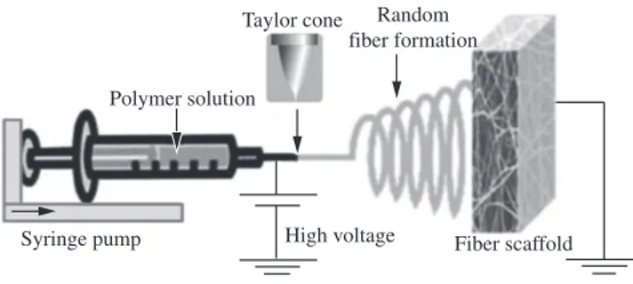
To optimize the electrospinning process parameters and to fabricate the ultrafine nanofibrous scaffold by using NANON electrospinning setup (NANON-01A, MECC Co., Ltd., Fukuoka, Japan). The electrospinning setup includes several parts. The basic layout is shown in Figure 1. The SF solutions for electrospinning were loaded into a 10 mL glass syringes equipped with blunt needle with a tip of 0.838 mm inner in diameter. The syringe was then placed in a syringe pump and needle was connected to the positive output of high voltage supply. The solution flow rates were tested at a range of 0.02, 0.05 and 0.08 mL/h respectively. The electrospinning voltage of 1.5, 2.0 and 2.5 kV.cm–1 was applied between the syringe tip and a collector covered with aluminum foil placed at 10 cm on which fibers were collected. All the electrospinning experiments were performed at room temperature and the process parameters applied dur ing the experiments are summarized in Table 1.
2.3. Viscosity measurements
In an attempt to correlate Rheology properties of various electrospinning solutions to electrospinnability, the viscosity of SF solutions (18, 20, 22 and 24 wt. (%)) in TFA (100%) was measured. The rheological measurements were performed on a Bohlin Gemini 200 HRnano Rheometer (Bohlin Instruments, UK) with a CP 4/40 cone-plate geometry (cone diameter 40 mm, angle 4°). The shear rate was linearly increased from 0.05 to 150/s.
Table 1. Specification of technological parameters applied during the electro-spinning.
Polymer concentration
(wt. (%))
Applied voltage (kV.cm–1)
3.2.1. Effect of SF concentration at 18 wt. (%) and its
operating parameters
At 18 wt. (%) concentration chain entanglements may not be enough, resulting in beads and fibers deposition on the collector (Figure 3). A possible reason for such an observation is that at low concentrations and viscosity, fibers will break up into droplets before reaching the collector due to the effects of surface tension30. Figure 3a, b and c show the effect of electric field on the fibers. Many short branches appeared in the accelerating voltages 1.5, 2.0 and 2.5 kV.cm–1 at the flow rate of 0.02 mL/h. Applied voltage below 1.5 kV.cm–1 did not permit electrospinning jet formations, resulting in no fiber deposition (data not shown). There is an optimal range of electric field strengths for a certain polymer/solvent system. Either too weak or too strong a field will lead to the formation of beaded fibers4. Increasing the flow rate from 0.02 to 0.05 mL/h and the applied voltage varied from 1.5-2.5 kV.cm–1 resulted in beads with interconnected fibers as shown in Figure 3d, e and f. Although small amount of fibers were produced, beads were still dominant on the collector. Though the flow rate increased to 0.08 mL/h, favorable fibrous did not occurred (Figure 3g, h and i). Significant beads defects were noticed at this condition suggest that jet takes longer time to dry due to the greater volume of solution drawn from the needle tip. As a result, the solvents in the deposited fibers may not have enough time to evaporate. Incomplete fiber drying also leads to the formation of ribbon like (or flattened) fibers as compared to fibers with a circular cross section31. This clearly suggests that the solution flow rate must also be accounted for the characterization of electrospun fiber morphology. Essentially, solution flow rate adjustments are made in order to maintain a stabilized Taylor cone during electrospinning32. It has been reported that at lower concentrations, not only the beads formed, but also they are harder to dry before they reach the collector at high flow rate33. The viscosity was not high enough for stable liquid jet formation and hence the beaded fibers were formed.
3.2.2. Effect of SF concentration at 20 wt. (%) and its
operating parameters
At 20 wt. (%) concentration it was found that fibers were predominantly deposited while the bead fraction remarkably decreased in comparison with 18 wt. (%) solution. As illustrated in Figure 4a, b and c, it was impossible to collect a continuous fiber. It
2.4. Characterization of electrospun fiber
The morphology and diameters of electrospun fibers were determined using scanning electron microscope (JSM-7400F, JEOL, Japan). The sample was sputter coated with a thin platinum layer using an auto sputter fine coater (E-1030 Ion sputter, Hitachi, Japan) before imaging. According to the SEM images, the diameter and distributions of ultrafine fibers were measured.
2.5. Fourier transform infra red (FT-IR) spectroscopy
To observe any chemical changes in SF fiber that may have been taking place in electrospinning solution (SF-TFA solution). The collected fibers were scraped from the aluminum foil and analyzed using an FTIR. The infrared spectra were obtained on a Perkin Elmer Spectrum 100 FT-IR system (Perkin Elmer, USA). Samples were prepared on KBr pellets and scanned against a blank KBr pellet background at the wave number range 4000-450 cm–1 with the resolution of 4.0 cm–1.
2.6. Statistics
One-way ANOVA statistical analysis was performed to investigate the effects of the solution concentration on fiber diameter.
3. Results and Discussion
3.1. Rheological properties of SF solution
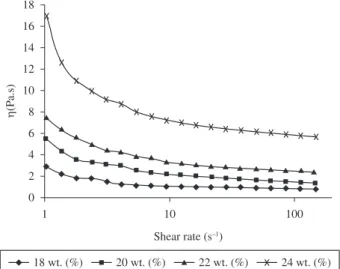
Rheological behavior of polymer solution examined repeatedly for studying the interactions between solvent and polymer. Figure 2 shows the rheological behavior of SF solutions with different concentrations at 18, 20, 22 and 24 wt. (%) respectively. Shear viscosity plotted against shear rate. The viscosity is nearly stable in the range of high shear rates. At low shear rates, molecules with preferred conformations that are long and thin are not oriented very well in the direction of the flow and have large effective cross-sections, leading to a relatively high viscosity. However, at high shear rates, the molecules align with the flow, giving much smaller effective cross sections and thus much lower viscosities. In case of the solutions of SF (18 and 20 wt. (%)), the values of viscosity were maintained constantly around 3 and 5.4 Pa.s, respectively, these values increased with increasing of concentration. Specifically, the viscosity increased from 7.2 to 16.87 Pa.s for solution concentration from 22 to 24 wt. (%). The solutions with higher concentrations showed higher viscosities, as might be expected for common SF solution. The decrease of shear viscosity against shear rate is known to due to entangled chain networks in polymer solution26. If a particular solution has a high viscosity, then solvent molecules spread more evenly over the entangled polymer. Therefore, a higher solution viscosity results in more polymer entanglement, which serves to maintain a continuous jet during electrospinning.
3.2. Electrospinning processing parameters
Electrospun nanofiber morphology is also heavily dependent on processing conditions. Therefore, processing parameters must be optimized in order to generate fibers as opposed to droplets. To investigate the concentration effect of the solution; the tip target distance for all concentrations was kept constant at 10 cm. The applied voltage and flow rate were varied in the range of 1.5-2.5 kV.cm–1 and 0.02-0.08 mL/h respectively. Most biomacromolecular nanofibers have been formed at the electric field range of 0.5-4 kV.cm–1[27-29].
in the collector which did not evaporate with varying accelerating voltage 1.5-2.5 kV.cm–1. The residual solvents may cause the fibers to fuse together while they make contact forming webs.
3.2.3. Effect of SF concentration at 22 wt. (%) and its
operating parameters
While using 22 wt. (%) SF solution; we observed primarily fibers when the applied applied voltage were 1.5-2.5 kV.cm–1 at the flow rate of 0.02 mL/h and found that the collection of the fibers was extremely low (Figure 5). There was a significant decrease in bead formation and the beads were more integrated into fibers. The electrospinning process was hard to maintain uniform fibers with the presence of junctions in the fibers as shown in Figure 5a, b and c. was hard to obtain fibers from the applied voltage varied in the range
voltage38 which we had observed in our case too. The fibrous structure becomes stable at flow rate 0.05 mL/h. As flow rate increases further to 0.08 mL/h, thicker fibers were produced with varied accelerating voltage and an irregular form of deposition occurred as shown in Figure 5g, h and i respectively.
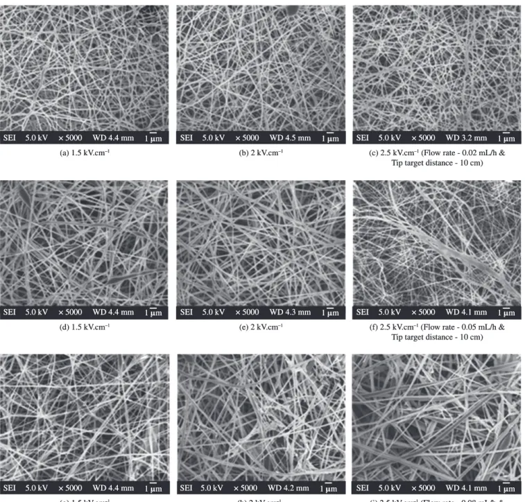
3.2.4. Effect of SF concentration at 24 wt. (%) and its
operating parameters
As the SF concentration was increased to 24 wt. (%), evidence of fusing fibers were obtained at 0.02 mL/h and there was a significant decrease in bead formation and the beads were more integrated into fibers (Figure 6a, b and c). More uniform fibers and the thicker diameters of fibers were formed with the increase of the The fibers may exhibit branching and splitting of the fibers which
varying the accelerating voltage (Figure 6g, h and i). Depending on the solution property, the effect of varying the voltage may have a significant effect on the fiber morphology. Figure 6e illustrates that experimental test runs with the aforementioned solution parameters having 0.05 mL/h volumetric flow rate and the applied voltage 2 kV.cm–1 allowed for the best results. The high volatility of TFA is advantageous for the rapid solidification of the electrified jet of the SF-TFA solution might be a possible reason why the electrospinning of SF is successful when using TFA. The high solution concentration and correspondingly high solution viscosity could be the possible causes resulting in an increase in the fiber diameter39. However, if the solution concentration is high then fibers cannot be formed due to the high viscosity, which makes it difficult to control the solution flow rate through the capillary.
SF concentration. Upon an increase in polymer concentration to 24 wt. (%) and thus by an increase in viscosity, the distance between beads decreased and smooth, uniform fibers were observed. An almost homogenous network of the electrospun SF fibers was observed with increasing the electric field strength from 1.5 to 2.0 kV.cm–1 decreased the bead density, while increasing the flow rate from 0.02 to 0.05 mL/h (Figure 6d, e and f). When the electric field was high enough to overcome the surface tension of SF solution, particularly in 2 kV.cm–1, uniform and homogeneous fibers were obtained (Figure 6e). However, while using an applied voltage 2.5 kV.cm–1 (Figure 6f) it was found that the fiber thus produced with many defects possibly due to increased elongation force and instability of charged jet induced by the stronger electric field. However, thicker fibers were produced and an irregular form of deposition occurred while using 0.08 mL/h at
(a) 1.5 kV.cm–1 (b) 2 kV.cm–1 (c) 2.5 kV.cm–1 (Flow rate - 0.02 mL/h &
Tip target distance - 10 cm) 1 µm
SEI 5.0 kV × 5000 WD 4.3 mm SEI 5.0 kV × 5000 WD 4.4 mm 1 µm SEI 5.0 kV × 5000 WD 4.4 mm 1 µm
(d) 1.5 kV.cm–1 (e) 2 kV.cm–1 (f) 2.5 kV.cm–1 (Flow rate - 0.05 mL/h &
Tip target distance - 10 cm) 1 µm
SEI 5.0 kV × 5000 WD 4.0 mm SEI 5.0 kV × 5000 WD 4.2 mm 1 µm SEI 5.0 kV × 5000 WD 4.2 mm 1 µm
(g) 1.5 kV.cm–1 (h) 2 kV.cm–1 (i) 2.5 kV.cm–1 (Flow rate - 0.08 mL/h &
Tip target distance - 10 cm) 1 µm
SEI 5.0 kV × 5000 WD 3.7 mm SEI 5.0 kV × 5000 WD 4.4 mm 1 µm SEI 5.0 kV × 5000 WD 3.7 mm 1 µm
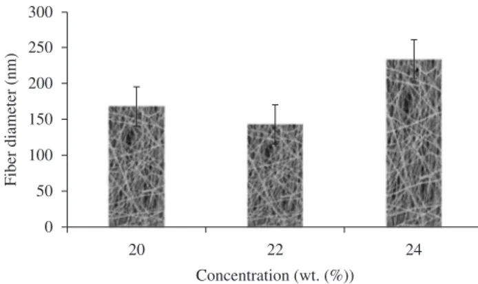
distribution is very high due to non-uniform fibers (Figure 4e; average diameter, 168 ± 8.9 nm; diameter distribution, 125-210 nm). At a SF concentration of 22 wt. (%), since there was still some form of spindle-like beads, only the diameters of the fibers without beads were chosen to be measured, fiber diameter distribution decreased with thin fibers (Figure 5e; average diameter, 143 ± 3.2 nm; diameter distribution, 122-158nm). An almost homogenous network of the electrospun SF fibers was observed at 24 wt. (%), the fiber diameter equally distributed due to the more uniform fibers (Figure 6e; average diameter, 234 ± 3.1 nm; diameter distribution, 225-255 nm). The average nanofiber diameter 22 and 24 wt. (%) SF electrospun web increased from 143 to 234 nm, respectively, A higher elongational viscosity induces a stronger stretching, resulting in fibers of finer
3.3. Fiber diameter distribution
The images obtained from scanning electron microscope were studied for the effect of the SF concentration and electric field on fiber diameter and its distribution. Mean diameters were compared between the samples that actually produced fibers with minimal beads. Thus, fibers produced from 20, 22 and 24 wt. (%) SF concentrations under the same conditions were compared (flow rate of 0.05 mL/h and applied voltage of 2 kV.cm–1 respectively). Figure 7 show the range of diameters for this concentration. For 20 wt. (%) SF concentration, fibers were predominantly deposited while the bead fraction remarkably decreased; only the diameters of the fibers without beads were chosen to be measured, the fiber diameter
(a) 1.5 kV.cm–1 (b) 2 kV.cm–1 (c) 2.5 kV.cm–1 (Flow rate - 0.02 mL/h &
Tip target distance - 10 cm) 1 µm
SEI 5.0 kV × 5000 WD 4.4 mm SEI 5.0 kV × 5000 WD 4.5 mm 1 µm SEI 5.0 kV × 5000 WD 3.2 mm 1 µm
(d) 1.5 kV.cm–1 (e) 2 kV.cm–1 (f) 2.5 kV.cm–1 (Flow rate - 0.05 mL/h &
Tip target distance - 10 cm) 1 µm
SEI 5.0 kV × 5000 WD 4.4 mm SEI 5.0 kV × 5000 WD 4.3 mm 1 µm SEI 5.0 kV × 5000 WD 4.1 mm 1 µm
(g) 1.5 kV.cm–1 (h) 2 kV.cm–1 (i) 2.5 kV.cm–1 (Flow rate - 0.08 mL/h &
Tip target distance - 10 cm) 1 µm
SEI 5.0 kV × 5000 WD 4.4 mm SEI 5.0 kV × 5000 WD 4.2 mm 1 µm SEI 5.0 kV × 5000 WD 4.1 mm 1 µm
4. Conclusion
Nanofibrous scaffold of SF were successfully produced in a standard electrospinning setup (NANON-01A). Although the parameter tests were extremely exhaustive, they provided exceptional insight regarding the complex process of electrospinning. Both the electrospinning solution and electrospinning apparatus parameters derived from these preliminary experiments provided the basis for all subsequent experiments in the study. From the data gathered, it was determined that an 24 wt. (%) SF-TFA solution would produce optimum fiber deposition when electrospun with an 18 gauge needle, 10 cm tip target distance, 2 kV.cm–1 potential and 0.05 mL/h flow rate. Optimally, a lower solution flow rate, while maintaining the Taylor cone is more ideal since it permits time for solvent evaporation and produces better fibers. A lower feed rate is more desirable as the solvent need more time for evaporation. Under optimized conditions, homogenous (not interconnected) SF fibers with a mean diameter of 234 nm were prepared. As the SF concentration was increased, the morphology of the deposition on the collector changed from spherical beads to interconnected fibrous networks. Drastic morphological changes were found when the concentration of the solution was changed. Compared to the other variables concentration and the corresponding viscosity are the most effective variables to control the fiber morphology. These parameters produced consistent results in multiple experimental test runs. When the concentration of SF solution was more than 24 wt. (%), the electrospinning process was hard to maintain due to the high viscosity of the solution. The rheological properties of SF solutions were improved by increasing the concentration of SF. Additionally, FT-IR results demonstrated that there was no chemical modification on SF and the developed mat could be used for prolong application.
Acknowledgements
D. Brahatheeswaran, would like to acknowledge the Japanese Government, Ministry of Education, Culture, Sports, Science and Technology (MEXT) for the scholarships provided for the doctoral studies.
References
1. Deitzel JM, Kleinmeyer JD, Harris D and Beck Tan NC. The effect of processing variables on the morphology of electrospun nanofibers and textiles. Polymer. 2001; 42:261-272. http://dx.doi.org/10.1016/S0032-3861(00)00250-0
2. Huang ZM, Zhang YZ, Kotaki M and Ramakrishna S. A review on polymer nanofibers by electrospinning and their applications in nanocomposites. Composites Science and Technology. 2003; 63:2223-2253. http://dx.doi. org/10.1016/S0266-3538(03)00178-7
3. Gibson P, Gibson HS and Rivin D. Transport properties of porous membranes based on electrospun nanofibers. Colloids and Surfaces A. 2001; 187-188:469-481. http://dx.doi.org/10.1016/S0927-7757(01)00616-1
4. Meechaisue C, Dubin R, Supaphol P, Hoven VP and Kohn J. Electrospun mat of tyrosine-derived polycarbonate fibers for potential use as tissue scaffolding material. Journal of Biomaterials Science Polymer Edition. 2006; 17(9):1039-1056. http://dx.doi.org/10.1163/156856206778365988
5. Buchko CJ, Chen LC, Shen Y and Martin DC. Processing and microstructural characterization of porous biocompatible protein polymer thin films. Polymer. 1999; 40:7397-7407. http://dx.doi.org/10.1016/ S0032-3861(98)00866-0
6. Katti DS, Robinson KW, Ko FK and Laurencin CT. Bioresorbable nanofiber-based systems for wound healing and drug delivery: optimization of fabrication parameters. Journal of Biomedical Material Research. 2004; 70B(2):286-296. PMid:15264311. http://dx.doi.org/10.1002/jbm.b.30041
7. Matthews JA, Wnek GE, Simpson DG and Bowlin GL. Electrospinning of collagen nanofibers. Biomacromolecules. 2002; 3(2):232-238. PMid:11888306. http://dx.doi.org/10.1021/bm015533u
diameter. Fiber diameter also increased with viscosity. It is widely reported that higher concentrations result in larger fiber diameters1,40-43.
In our case also we found that solution concentration plays the most significant factor controlling the fiber diameter in the electrospinning process. The fiber diameter of the 24 wt. (%) concentration of SF nanofibers was statistically highly significant compared to the lower concentration of 20 and 22 wt. (%) SF nanofibers (significant factor p < 0.0001).
3.4. Spectroscopic characterization of SF fibers
The IR spectrum of the SF fiber is given in Figure 8. The SF Raw (Figure 8a) displayed a strong absorption band at 3239 cm–1 (NH-stretching), assigned to the hydrogen bonded NH groups, in addition to the characteristic amide bands at 1698 and 1631 cm–1 (amide I), 1518 cm–1 (amide II), 1263 and 1231 cm–1 (amide III) assigned to the
β sheet, as described elsewhere44,45. Spectra shows strong twin bands at 996 and 976 cm–1 however no bands at 1015 and 965 cm–1 which can be conclude that in the part of silk fibroin the glycine and alanine residues are arranged alternately just as in periodic sequence46. This conclusion is supported by the presence of sharp bands at 1631 and 1518 cm–1 in the amide I and II range, respectively. Figure 8b shows the structure of the fiber mat which was analyzed after two months of its preparation, there is no substantial spectral change between fibers and raw material. The spectrum conveys that TFA has not profound inference on the chemical structure and also retains the absorption bands at 1698 and 1631 cm–1 (amide I), 1518 cm–1 (amide II), 1263 and 1231 cm–1 (amide III).
Figure 7. The range of fiber diameters for the SF concentration.
Physics. 1998; 199:2385-2394. http://dx.doi.org/10.1002/(SICI)1521-3935(19981101)199:11%3C2385::AID-MACP2385%3E3.0.CO;2-O 27. Huang L, Negapudi K, Apkarian R and Chaikof EL. Engineered
collagen-PEO nanofibers and fabrics. Journal of Biomaterials Science Polymer Edition. 2001; 12:979-994. http://dx.doi.org/10.1163/156856201753252516 28. Um IC, Fang D, Hsiao BS, Okamoto A and Chu B. Electro-spinning
and electro-blowing of hyaluronic acid. Biomacromolecules. 2004; 5:1428-1436. PMid:15244461. http://dx.doi.org/10.1021/bm034539b 29. Huang ZM, Zhang YZ, Ramakrishna S and Lim CT. Electrospinning
and mechanical characterization of gelatin nanofibers. Polymer. 2004; 45:5361-5368. http://dx.doi.org/10.1016/j.polymer.2004.04.005 30. Fong H, Liu W, Wang C and Vaia RA. Generation of electrospun fibers
of nylon 6 and nylon 6-montmorillonite nanocomposite. Polymer. 2002; 43:775-780. http://dx.doi.org/10.1016/S0032-3861(01)00665-6 31. Megelski S, Stephens JS, Chase DB and Rabolt JF. Micro- and nanostructured
surface morphology on electrospun polymer fibers. Macromolecules. 2002; 35(22):8456-8466. http://dx.doi.org/10.1021/ma020444a
32. Ramakrishna S, Fujikara K, Teo WE, Lim TC and Ma Z. Electrospinning and nanofibers. Singapore: World Scientific publishing; 2005. http://dx.doi.org/10.1142/9789812567611
33. Zong X, Kim K, Fang D, Ran S, Hsiao BS and Chu B. Structure and process relationship of electrospun bioabsorbable nanofiber membranes. Polymer. 2002; 43:4403-4412. http://dx.doi.org/10.1016/S0032-3861(02)00275-6 34. El-Refaie K, Layman JM, Watkins JR, Gary LB, Matthews JA, Simpson DG
et al. Electrospinning of poly(ethylene-co-vinyl alcohol) fibers. Biomaterials. 2003; 24:907-913. http://dx.doi.org/10.1016/S0142-9612(02)00422-2 35. Hohman MM, Shin M, Rutledge G and Brenner MP. Electrospinning
and electrically forced jets. II. Applications. Physics of Fluids. 2001; 13:2221-2236. http://dx.doi.org/10.1063/1.1384013
36. Koombhongse S, Liu W and Reneker DH. Flat polymer ribbons and other shapes by electrospinning. Journal of Polymer Science Part B: Polymer Physics. 2001; 39:2598-2606. http://dx.doi.org/10.1002/polb.10015 37. Fong H, Chun I and Reneker DH. Beaded nanofibers formed during
electrospinning. Polymer. 1999; 40:4585-4592. http://dx.doi.org/10.1016/ S0032-3861(99)00068-3
38. Zhong XH, Kim KS, Fang DF, Ran SF, Hsiao BS and Chu B. Structure and process relationship of Electrospun bioabsorbable nanofiber membranes. Polymer. 2002; 43:4403-4412. http://dx.doi.org/10.1016/ S0032-3861(02)00275-6
39. Yuan X, Zhang Y, Dong C and Sheng J. Morphology of ultrafine polysulfone fibers prepared by electrospinning. Polymer International. 2004; 53(11):1704-1710. http://dx.doi.org/10.1002/pi.1538
40. He JH, Wan YQ and Yu JY. Effect of concentration on electrospun polyacrylonitrile (PAN) nanofibers. Fibers and Polymers. 2008; 9:140-142. http://dx.doi.org/10.1007/s12221-008-0023-3
41. Greiner A and Wendorff J. Electrospinning: a fascinating method for the preparation of ultrathin fibers. Angewandte Chemie International Edition. 2007; 46:5670-5703. PMid:17585397. http://dx.doi.org/10.1002/ anie.200604646
42. Li D and Xia Y. Electrospinning of Nanofibers: Reinventing the Wheel? Advanced Materials. 2004; 16(14):1151-1170. http://dx.doi.org/10.1002/ adma.200400719
43. Subbiah T, Bhat GS, Tock RW, Parameswaran S and Ramkumar SS. Electrospinning of nanofibers. Journal of Applied Polymer Science. 2005; 96(2):557-569. http://dx.doi.org/10.1002/app.21481
44. Asakura T, Kuzuhara A, Tabeta R and Saito H. Conformation characterization of Bombyx mori silk fibroin in the solid-state by high-frequency C- 13 cross-polarization magic angle spinning NMR, X-Ray Diffraction, and Infrared Spectroscopy. Macromolecules. 1985; 18:1841-1845. http://dx.doi.org/10.1021/ma00152a009
45. Li M, Lu S, Wu Z, Yan H, Mo J and Wang L. Study on porous silk fibroin materials: I. Fine structure of freeze dried silk fibroin. Journal of Applied Polymer Science. 2001; 79(12):2185-2191. http://dx.doi.org/10.1002/1097-4628(20010321)79:12%3C2185::AID-APP1026%3E3.0.CO;2-3 46. Asai M, Tsuboi H, Shimanouchi T and Mizushima S. Infrared spectra of
polypeptides and related compounds. The Journal of Physical Chemistry. 1955; 59:322-325. http://dx.doi.org/10.1021/j150526a011
8. Reneker DH and Chun I. Nanometer diameter fibers of polymer, produced by electrospinning. Nanotechnology. 1996; 7:216-223. http://dx.doi. org/10.1088/0957-4484/7/3/009
9. Ohgo K, Zhao C, Kobayashi M and Asakura T. Preparation of non-woven nanofibers of Bombyx mori silk, Samia cynthia ricini silk and recombinant hybrid silk with electrospinning method. Polymer. 2002; 44:841-846. http://dx.doi.org/10.1016/S0032-3861(02)00819-4
10. Wnek GE, Carr ME, Simpson DG and Bowlin GL. Electrospinning of nanofiber fibrinogen Structures. Nano Letters. 2003; 3(2):213-216. http://dx.doi.org/10.1021/nl025866c
11. Fang X and Reneker DH. DNA fibers by electrospinning. Journal of Macromolecular Science. 1997; B36(2):169-173. http://dx.doi. org/10.1080/00222349708220422
12. Jiang H, Fang D, Hsiao BS, Chu B and Chen W. Optimization and characterization of dextran membranes prepared by electrospinning. Biomacromolecules. 2004; 5(2):326-333. PMid:15002991. http://dx.doi. org/10.1021/bm034345w
13. Son WK, Youk JH and Park WH. Preparation of ultrafine oxidized cellulose mats via electrospinning. Biomacromolecules. 2004; 5(1):197-201. PMid:14715026. http://dx.doi.org/10.1021/bm034312g 14. Li WJ, Mauck RL and Tuan RS. Electrospun nanofibrous scaffolds:
Production, characterization, and applications for tissue engineering and drug delivery. Journal of Biomedical Nanotechnology. 2005; 1(3):259-275. http://dx.doi.org/10.1166/jbn.2005.032
15. Min BM, Jeong L, Nam YS, Kim JM, Kim JY and Park WH. Formation of silk fibroin matrices with different texture and its cellular response to normal human keratinocytes. International Journal of Biological Macromolecules. 2004; 34:223-230. PMid:15556229. http://dx.doi. org/10.1016/j.ijbiomac.2004.08.004
16. Park WH, Ha WS, Ito H, Miyamoto T, Inagaki H and Noishiki Y. Relationships between antithrombogenicity and surface free energy of regenerated silk fibroin films. Fibers and Polymer. 2001; 2:58-63. http://dx.doi.org/10.1007/BF02875259
17. Santin M, Motta A, Freddi G and Cannas M. In vitro evaluation of the inflammatory potential of the silk fibroin. Journal of Biomedical Material Research. 1999; 46:382-389. http://dx.doi.org/10.1002/(SICI)1097-4636(19990905)46:3%3C382::AID-JBM11%3E3.0.CO;2-R
18. Putthanarat S, Zarkoob S, Magoshi J, Chen JA, Eby RK and Stone M, Effect of processing temperature on the morphology of silk membranes. Polymer. 2002; 43:3405-3413. http://dx.doi.org/10.1016/S0032-3861(02)00161-1 19. Kang GD, Lee KH, Ki CS, Nahm JH and Park YH. Silk Fibroin/Chitosan
conjugate crosslinked by tyrosinase. Macromolecular Research. 2004; 12(5):534-539. http://dx.doi.org/10.1007/BF03218439
20. Ayutsede J, Gandhi M, Sukigara S, Micklus M, Chen HE and Ko F. Regeneration of Bombyx mori silk by electrospinning. Part 3: characterization of electrospun nonwoven mat. Polymer. 2005; 46:1625-1634. http://dx.doi.org/10.1016/j.polymer.2004.11.029 21. Zhang X, Baughman CB and Kaplan DL. In vitro evaluation of
electrospun silk fibroin scaffolds for vascular cell growth. Biomaterials. 2008; 29:2217-2227. PMid:18279952. PMCid:2698960. http://dx.doi. org/10.1016/j.biomaterials.2008.01.022
22. Zarkoob S, Reneker DH, Eby RK, Hudson SD, Ertley D and Adams WW. Structure and morphology of nano electrospun silk fibers. Polymer Preprints. 1998; 39:244-245.
23. Buchko CJ, Chen LC, Shen Y and Marthin DC. Processing and microstructural characterization of porous biocompatible protein polymer thin films. Polymer, 1999; 40:7397-7407. http://dx.doi.org/10.1016/ S0032-3861(98)00866-0
24. Jin HJ, Fridrikh SV, Rutledge GC and Kaplan DL. Electrospinning Bombyx mori Silk with Poly(ethylene oxide). Biomacromolecules. 2002; 3:1233-1239. http://dx.doi.org/10.1021/bm025581u
25. Ogho K, Zhao C, Kobayashi M and Asakura T. Preparation of non-woven nanofibers of Bombyx mori silk, Samia cynthia ricini silk and recombinant hybrid silk with electrospinning method. Polymer. 2003; 44:841-846. http://dx.doi.org/10.1016/S0032-3861(02)00819-4