Analysis of ply damage
using computational micro-mechanics:
transverse shear failure mechanisms
Tiago Vaz Maia Vieira
Dissertation submitted to
Faculdade de Engenharia da Universidade do Porto for the degree of:
Mestre em Engenharia Mecˆanica
Advisor:
Prof. Dr. Albertino Arteiro
Sec¸c˜ao de Mecˆanica Aplicada (SMAp) Departamento de Engenharia Mecˆanica (DEMec) Faculdade de Engenharia da Universidade do Porto (FEUP)
The work presented in this dissertation was performed at the Section of Applied Mechanics
Department of Mechanical Engineering Faculty of Engineering
University of Porto Porto, Portugal.
Tiago Vaz Maia Vieira
E-mail: [email protected] Albertino Jos´e Castanho Arteiro E-mail: [email protected]
Faculdade de Engenharia da Universidade do Porto Departamento de Engenharia Mecˆanica
Sec¸c˜ao de Mecˆanica Aplicada
Rua Dr. Roberto Frias s/n, Edif´ıcio L, Sala L303 4200-465 Porto
Abstract
Qualification of fibre-reinforced polymers for the manufacturing of structural components in the aeronautical industry is usually associated with extensive and costly experimental campaigns. The burden of testing is immense and materials should be characterised under different loading stress states (tensile, compressive, shear) to assess their structural in-tegrity during service conditions. Recent developments in microscale simulation, together with increased computational power and improvements in modeling tools, can be used to alleviate this scenario.
The effect of ply thickness on the onset of ply damage, in terms of matrix cracking, is extremely important for the prediction of the mechanical response of laminated composite structures. This is of particular significance when dealing with the most recent spread-tow, ultra-thin plies, where ply thickness can be extremely low.
By reducing the ply thickness in a multidirectional laminate, an in-situ effect occurs consisting of matrix cracking suppression, which provides high strength and delays damage onset, thereby enhancing the fatigue life of a composite laminate.
During the last few years, computational micro-mechanics proved to be a reliable tool for understanding of the in-situ effect. In this dissertation, a micro-mechanical model is used to study the effect of ply thickness on constrained 90◦ plies subjected to transverse shear loading, thus extending the current understanding of such phenomenon.
The micro-mechanical framework proposed in this work is able to accurately represent the micro-mechanical response of ultra-thin plies when subjected to transverse shear load-ing, including (i) the mechanics of transverse shear cracking onset and propagation, (ii) a consistent orientation of the fracture plane of the 90◦ lamina, (iii) the constraining ef-fect observed in the lamina embedded in a multidirectional laminate (iv) the gradual, slow stress relaxation and progressive transverse cracking observed in very thin plies, and consequent increase of the crack density, and (v) an in-situ effect in transverse shear.
Keywords: Thin-ply composite laminates, In-situ effect, Matrix cracking, Ply damage, Computational micro-mechanics, Finte Element Analyses.
Resumo
A caracteriza¸c˜ao de pol´ımeros refor¸cados com fibras para a produ¸c˜ao de componentes estruturais na ind´ustria aeron´autica ´e usualmente associada a campanhas experimentais extensas e dispendiosas. A dificuldade no teste deste tipo de materiais ´e imensa, e estes devem ser caracterizados sob diferentes tipos de solicita¸c˜ao (tra¸c˜ao, compress˜ao, corte), de forma a avaliar a sua integridade estrutural nas suas condi¸c˜oes de servi¸co. Desen-volvimentos recentes na simula¸c˜ao `a micro-escala, juntamente com o aumento do poder computacional e melhorias em ferramentas de modela¸c˜ao, podem ser usadas para aliviar este cen´ario.
O efeito da espessura da camada na inicia¸c˜ao de dano, em termos de fendas na matriz, ´e extremamente importante para a previs˜ao do comportamento mecˆanico de estruturas laminadas comp´ositas. O mesmo ´e de particular interesse quando se est´a perante os mais recentes comp´ositos de camadas ultrafinas, onde a espessura da camada ´e extremamente pequena.
Ao reduzir-se a espessura da camada num laminado multidirecional, um efeito in-situ ocorre, consistindo na supress˜ao de fendas na matriz, que conduz a uma maior resistˆencia mecˆanica e atrasa o in´ıcio do dano, deste modo aumentando a resistˆencia e a vida `a fadiga do laminado comp´osito.
Ao longo dos ´ultimos anos, a micromecˆanica computacional provou ser uma ferramenta robusta para se compreender o efeito in-situ. Nesta disserta¸c˜ao, um modelo micromecˆanico ´e usado para estudar o efeito da espessura da camada, em camadas a 90◦ embebidas e submetidas a uma carga de corte transversal, estendendo assim o atual conhecimento deste fen´omeno.
A abordagem micromecˆanica proposta neste trabalho ´e adequada para a representa¸c˜ao precisa da resposta micromecˆanica de camadas ultrafinas quando sujeitas a uma solicita¸c˜ao de corte transversal, incluindo (i) a mecˆanica de in´ıcio e propaga¸c˜ao de uma fenda por corte transversal, (ii) uma orienta¸c˜ao do plano de fratura da camada a 90◦ consistente, (iii) o efeito de restri¸c˜ao observado na camada embebida num laminado multidirecional, (iv) uma gradual relaxa¸c˜ao de tens˜ao e progressiva fissura¸c˜ao transversal observada em camadas muito finas, e consequente aumento da densidade de fissura¸c˜ao, e (v) um efeito in-situ em corte transversal.
Keywords: Laminados comp´ositos de camadas ultrafinas, Efeito in-situ, Fendas na matriz, Dano da camada, Micro-mecˆanica computacional, An´alise de Elementos Finitos.
To my parents,
’And however difficult life may seem,
there is always something you can do, and succeed at. It matters that you don’t just give up.’
Acknowledgements
This dissertation ends up a five-year academic route in Mechanical Engineering, where I had contact with the most extraordinary people I ever saw. I sincerely believe that these people not only strongly contributed to the quality of the present work, but also to the whole intellectual development I got during these years. I hope that somehow I have already expressed my praise to all of them, which are certainly not limited to those mentioned here.
Firstly, a special gratification should be given to my advisor, Prof. Dr. Albertino Arteiro, for his scientific rigor, organization, and outstanding capacity in solving problems. This opportunity to work in a team with him was highly motivating for me, as I was conscious I was working with a great professional. I am pretty sure that this was an experience that I will never forget.
Secondly, I would also express my heartfelt gratitude to the Section of Applied Mechanics from the Faculty of Engineering of the University of Porto. Particularly I would like to thank Prof. Dr. Paulo Tavares de Castro, Prof. Dr. Jos´e Dias Rodrigues, Prof. Dr. Pedro Ponces Camanho, Prof. Dr. Renato Natal Jorge, and Prof. Dr. Jos´e Soares Esteves, for their constant effort in teaching and captivating students to the branch of Machine Design and Structural Engineering.
I too owe a special thanks to my friends, Ant´onio Couto Carneiro and Miguel Couto Aires, for never letting one single doubt unclarified, and helping me with the smallest things that eventually made a big difference in the present work.
Finally, I want to thank all the people that were an important part of my life during the past five years.
To my long time friends Andr´e Parente, Miguel ˆAngelo, Orlando Carri¸co and Rui Raj˜ao, for the genuine friendship we established since the beginnings of college. Part of what we are today, we owe to this friendship, where the jokes, the football games, the study, and mainly the personal support, were always the pillars of such relationship.
To all the friends I made in FEUP and accompanied me throughout this journey, espe-cially Jo˜ao Filipe, Lu´ıs Ramos, Miguel Dantas, Pedro Camacho and Tiago Teixeira. This is a farewell to the academic life, however, an introduction to a new stage awaits us, thus, it is only a “see you soon”. You can always count on me, and I wish you all the best.
To my nuclear family, my greatest acknowledgments are adressed. To my parents Maria das Dores and Manuel Vieira, the humblest human beings I ever met, for teaching me the value of honest work, for their unconditional love and support, and for always believing in my capacities. The man I am today I owe you. To my sister Maria Vaz, for being always present in my life, and helping me in taking care of our beloved parents. To my brother in law Samuel Dantas and my uncle Jos´e Rodrigues, whose their silent example, taught me that, inside the engineering world, the humility and hard work need to be present, both at the same level, on our daily routine. Finally, to my beloved goddaughter Maria Beatriz, that although being a baby, is capable of either putting a ripped smile on the godfather’s face, or motivating him to give his best.
Last, but not least, to Marta Pires, my lucky charm, whose, although has not accompa-nied me this journey since the beginning, was crucial to its conclusion. For her tremendous patience in these last months always accompanied by incessant gestures of affection and true love.
My sincere esteem to you all,
Tiago Vaz Maia Vieira
Contents
Abstract i Resumo iii Acknowledgements ix Nomenclature xix 1 Introduction 1 1.1 Background . . . 1 1.2 Motivation . . . 31.2.1 New composite materials technologies . . . 3
1.2.2 Spread-tow thin-ply technology . . . 3
1.3 Objetives . . . 4
1.4 Thesis layout . . . 5
2 State-of-art and literature review 7 2.1 Thin-ply composite laminates . . . 7
2.1.1 Introduction . . . 7
2.1.2 Opportunities in manufacturing and design . . . 8
2.2 Ply thickness scaling and its effect on composite laminates . . . 10
2.2.1 Introduction . . . 10
2.2.2 Matrix cracking and in-situ effect . . . 10
2.2.3 In-situ strengths . . . 11
2.3 Computational micro-mechanics . . . 20
2.3.1 Introduction . . . 20
2.3.2 Micro-mechanical modelling . . . 22
2.3.3 Analysis of the in-situ effect . . . 23
3 Computational micro-mechanics. Model formulation 29 3.1 Constitutive modelling . . . 29
3.1.1 Reinforcing fibres . . . 30
3.1.2 Epoxy matrix . . . 30
3.1.3 Fibre-matrix interface . . . 31
3.1.4 Homogenised outer plies . . . 32
3.1.5 Plies interface . . . 34
3.2 Finite element modelling . . . 34
3.2.1 Introduction . . . 34
3.2.2 Finite element discretisation . . . 34
CONTENTS
3.2.4 Transverse shear deformation in the RVE . . . 42
3.3 Model execution definitions . . . 45
3.3.1 Introduction . . . 45
3.3.2 Quasi-static analysis with ABAQUS®/Explicit . . . 45
3.3.3 Energy balance . . . 45
3.3.4 Mass scaling . . . 46
4 Micro-mechanical analysis of ply damage under transverse shear stress. Numerical results 51 4.1 Mechanics of transverse shear cracking . . . 51
4.2 Fracture plane orientation . . . 62
4.3 Normalised crack height . . . 67
4.4 Homogenised stress-strain response . . . 68
4.5 In-situ effect . . . 73
5 Conclusion 75 5.1 Conclusions . . . 75
5.2 Future Work . . . 76
References 79 A Analysis of ply damage using computational micro-mechanics - In-plane shear fail-ure mechanisms 89 A.1 Introduction . . . 89
A.2 Finite element modelling . . . 89
A.2.1 Loading and Boundary Conditions . . . 89
List of Figures
1.1 Schematic representation of a FRP composite laminate. . . 2 2.1 Schematic representation of a thin-ply and thick-ply morphology (adapted
from [22]). . . 7 2.2 Schematic illustration of ply drops with thin and thick plies (adapted from
Arteiro et al. [23]). . . 8 2.3 Transverse matrix cracks in a cross-ply laminate, where 1 stands for the
longitudinal (fibres) direction, 2 the transverse direction and 3 the through-thickness direction of the embedded 90◦ lamina (adapted from Sebaey et al. [28]). . . 11 2.4 Cracking strain of different glass fibre-reinforced polymer cross-ply
lami-nates (adapted from Garrett and Bailey [40] and Parvizi et al. [41]). . . 11 2.5 In-situ effect on the transverse tensile strength of an embedded 90◦ ply
(adapted from Flaggs and Kural [31]). . . 12 2.6 In-situ transverse tensile strength of an inner 90◦ ply (adapted from Dvorak
and Laws [32]). . . 13 2.7 Schematic views of embedded (inner) and outer plies and in-situ transverse
tensile strength prediction (adapted from Camanho et al. [33]). . . 14 2.8 Linear and nonlinear predictions for the in-situ in-plane shear strength of
an embedded (inner) and outer ply (adapted from Camanho et al. [33]). . . 17 2.9 Definitions of the parameters ηL and ηT (adapted from Camanho et al. [47]). 18
2.10 Transverse shear cracking scenario in multidirectional laminates (adapted from Olsson [48]). . . 19 2.11 Predictions for the in-situ transverse shear strength of a thin embedded ply. 19 2.12 Length-scales for composite laminate damage modelling (adapted from Arteiro
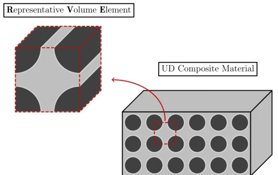
et al. [81]). . . 21 2.13 A schematic UD composite material and definition of representative volume
element. . . 22 2.14 Normalised crack length as a function of applied strain for different 90◦ ply
thicknesses (adapted from Arteiro et al [15]). . . 25 2.15 Homogenised stress-strain curves of the embedded 90◦ ply for different ply
thicknesses (adapted from Arteiro et al [15]). . . 26 2.16 COD as a function of applied strain for different 90◦ply thicknesses (adapted
from Arteiro et al [15]). . . 26 2.17 In-situ transverse tensile strength as a function of the ply thickness (adapted
from Arteiro et al. [15]). . . 27 2.18 In-situ transverse compressive strength as a function of ply thickness (adapted
LIST OF FIGURES
3.1 RVE of a laminate with a discretised 0.02 mm thick 90◦ lamina (adapted from Arteiro et al. [16]). . . 29 3.2 Yield curves given in Equivalent Stress vs. Equivalent Plastic Strain . . . . 32 3.3 Schematic of the RVE of a thin-ply sublaminate (adapted from Arteiro et
al. [15]). . . 35 3.4 Schematic representation of an FE discretisation of part of an RVE with a
0.040 mm thick transverse ply. . . 37 3.5 Schematic representation of the loading and boundary conditions applied to
the micromechanical model for the transverse shear analysis (for simplicity, the loading and boundary conditions are represented separately here, but applied simultaneously in the FE model). . . 40 3.6 Schematic representation of a pure transverse shear stress state applied to
the micro-mechanical model. . . 41 3.7 Homogenised stress-strain curves obtained after performing a first-order
volumetric homogenisation. . . 42 3.8 Comparison between the homogenised transverse shear strain (|γ230 |) and
the applied transverse shear strain ( ¯γ23). . . 43
3.9 Comparison between the evolutions of γ230 and γ230,Eq throughout the step time for a representative analysis. Curve fitting (gray interrupted line) is performed just on the region of γ230 prior to damage onset (full black line). . 44 3.10 Comparison between the equivalent transverse shear strain (γ230,Eq) and the
homogenised transverse shear strain (|γ230 |). The triangular markers repre-sent damage initiation, while the circular markers reprerepre-sent complete dam-age penetration through the thickness. . . 44 3.11 Internal and kinetic energies of a representative FE analysis. . . 46 3.12 Internal and kinetic energies after implementing mass scaling on a
repre-sentative analysis. . . 49 4.1 Contour plots of the matrix damage variable (SDV3) on an RVE of a
0.020 mm thick 90◦ lamina of a sublaminate with 0◦ outer plies (only the 90◦ lamina is presented). . . 53 4.2 Contour plots of the matrix damage variable (SDV3) on an RVE of a
0.040 mm thick 90◦ lamina of a sublaminate with 0◦ outer plies (only the 90◦ lamina is presented). . . 55 4.3 Contour plots of the matrix damage variable (SDV3) on an RVE of a
0.060 mm thick 90◦ lamina of a sublaminate with 0◦ outer plies (only the 90◦ lamina is presented). . . 56 4.4 Contour plots of the matrix damage variable (SDV3) on an RVE of a
0.100 mm thick 90◦ lamina of a sublaminate with 0◦ outer plies (only the 90◦ lamina is presented). . . 58 4.5 Contour plots of the matrix damage variable (SDV3) on an RVE of a
0.140 mm thick 90◦ lamina of a sublaminate with 0◦ outer plies (only the 90◦ lamina is presented). . . 59 4.6 Schematic explanation of the sequence damage events leading to
fibre-matrix interface debonding, for an RVE of a 0.040 mm thick 90◦ lamina of a sublaminate with 0◦ outer plies (only the 90◦ lamina is presented). . . 61
LIST OF FIGURES
4.7 Contour plots of the matrix damage variable (SDV3) in the RVE of 0.020 mm thick 90◦laminae of sublaminates with 0◦outer plies (only the 90◦lamina is presented), and the corresponding orientations of the fracture plane (αFP)
for the different fibre distributions. . . 63 4.8 Contour plots of the matrix damage variable (SDV3) in the RVE of 0.040 mm
thick 90◦laminae of sublaminates with 0◦outer plies (only the 90◦lamina is presented), and the corresponding orientations of the fracture plane (αFP)
for the different fibre distributions. . . 64 4.9 Contour plots of the matrix damage variable (SDV3) in the RVE of 0.060 mm
thick 90◦laminae of sublaminates with 0◦outer plies (only the 90◦lamina is presented), and the corresponding orientations of the fracture plane (αFP)
for the different fibre distributions. . . 66 4.10 Contour plot of the matrix damage variable (SDV3) in an RVE of 0.080 mm
thick 90◦ lamina of a sublaminate with 0◦ outer plies (only the 90◦ lamina is presented), and the corresponding orientation of the fracture plane (αFP). 66
4.11 Orientation of the fracture plane (αFP) as a function of the ply thickness. . 67
4.12 Schematic explanation of the normalised crack height definition. . . 67 4.13 Normalised crack height as a function of γ0,Eq23 for sublaminate RVEs with
0.020 mm, 0.060 mm, 0.100 mm and 0.120 mm thick transverse plies. . . 68 4.14 Homogenised stress-strain curves of the RVEs with an embedded 90◦ ply
for sublaminates with 0◦ outer plies. . . 72 4.15 In-situ equivalent elastic transverse shear strain at failure as a function of
ply thickness (the dotted line is a trendline fitted to the numerical results). 73 A.1 Schematic suggestion of the loading and boundary conditions to apply to
the micromechanical model for the in-plane shear analysis (for simplicity, the loading and boundary conditions are represented separately here, but should be applied simultaneously in the FE model). . . 90
List of Tables
3.1 Fibre diameter, fibre volume fraction and properties of the carbon fibres
[15; 16]. . . 30
3.2 Properties of the epoxy matrix [15; 16]. . . 32
3.3 Fibre-matrix interface properties [15; 16]. . . 33
3.4 Properties of the homogenised outer plies (IM7/8552) [15; 16]. . . 33
3.5 Interlaminar interface properties of the IM7/8552 carbon/epoxy composite system [15; 16]. . . 34
3.6 Dimensions of the thin-ply sublaminate RVE and random fibre distributions. 36 3.7 Different models to assess remote loading on the RVE. . . 41
Nomenclature
General Abbreviations
2D Bi-Dimensional
3D Three-Dimensional
BK Benzeggagh-Kenane
CFRP Carbon Fibre-Reinforced Polymer CMM Computational Micro-Mechanics COD Crack Opening Displacement DIC Digital Image Correlation
ERR Energy Release Rate
FAW Fibre Areal Weight
FPF First-Ply Failure
FRP Fibre-Reinforced Polymer
FE Finite Element
LEFM Linear Elastic Fracture Mechanics
LPF Last-Ply Failure
NCF Non-Crimp Fabrics
PBC Periodic Boundary Condition SEM Scanning Electron Microscope RVE Representative Volume Element
UD Unidirectional
Latin Variables
a RVE width (y-direction)
b RVE thickness (z-direction) c RVE length (x-direction)
cd Dilatational wave speed in a FE
Df Fibre diameter
E Young’s modulus
E1 Longitudinal Young’s modulus
E2 Transverse Young’s modulus
EI Internal energy
EV Viscous energy dissipated
NOMENCLATURE
EKE Kinetic energy
EIHE Internal heat energy
EW Work done by externally applied loads
EP W, ECW Work done by contact and constraint penalties
EM W Work done by propelling added masses
EHF Heat energy through external fluxes
Etotal Total energy
G Shear modulus
G12 In-plane shear modulus
G23 Transverse shear modulus
Gc Critical energy release rate
GIc Critical ERR in mode I GIIc Critical ERR in mode II GIIIc Critical ERR in mode III
h Embedded homogenised material size hc Transverse crack height
K Stiffness
k RVE integration point
Lmin FE characteristic length
Np RVE total number of integration points
SL In-plane shear strength
SLis In-situ in-plane shear strength ST Transverse shear strength
STis In-situ transverse shear strength T0 Stress-free temperature
t Ply thickness
tout Outer ply thickness
V RVE volume
Vf Fibre volume fraction
Vk Associated volume of the RVE integration point
w Applied vertical (z-direction) displacement on the RVE ˙
w Applied vertical (z-direction) velocity on the RVE
XT Tensile strength
XC Compressive strength
YCis In-situ transverse compressive strength YTis In-situ transverse tensile strength
Greek Variables
α Thermal expansion coefficient
α0 Fracture angle
α11 Longitudinal thermal expansion coefficient
α22 Transverse thermal expansion coefficient
NOMENCLATURE
αFP Fracture plane angle
β Shear stress-strain relation non-linearity parameter γ23 Transverse shear strain
¯
γ23 Applied transverse shear strain
γ230 Homogenised transverse shear strain γ230,Eq Equivalent applied transverse shear strain γk
23 Transverse shear strain determined at an integration point
∆t Step time increment
η Mixed-mode interaction parameter ηL Longitudinal friction coefficient
ηL,is In-situ longitudinal friction coefficient
ηT Transverse friction coefficient
ηT ,is In-situ transverse friction coefficient
θ Orientation of the outer plies λ, µ Lam´e constants
ρ Mass density
ν Poisson’s ratio
ν12 Major in-plane Poisson’s ratio
ν23 Transverse Poisson’s ratio
νp Plastic Poisson’s ratio
τ10,τ20 Interfacial shear strengths τ30 Interfacial normal strength τ23 Transverse shear stress
¯
τ23 Applied transverse shear stress
τ230 Homogenised transverse shear stress
τ23k Transverse shear stress determined at an integration point φ Ply configuration parameter
ωmax Maximum eigenfrequency of an assembled mesh
Chapter 1
Introduction
This introductory chapter provides the context for the current dissertation. A brief intro-duction to the increasing importance of composite materials in the design and development of new structural components, particularly for the aeronautical, automotive and marine industries, is presented. Then, a new manufacturing technology for composite laminates is exposed, which introduces the motivation of the present research, whose objectives are formally defined afterwards. Finally, the thesis layout is provided at the end of the chapter.
1.1
Background
A composite material is the result of a macroscopic combination between two or more dif-ferent materials. Such combination is advantageous, as it leads to a material that exhibits superior properties than those of the individual constituent materials acting independently [1; 2]. Most man-made composite materials are made from two materials: a reinforcement material typically in the form of fibres, and a base matrix material. The stiffness and strength present in the composite come from the reinforcement, while the matrix is re-sponsible to keep the fibres together, protect them against environmental threats, and transfer the load between them. Typically, the composite materials emerge on nature under three diferent types: fibrous composites, which consist of continuous or discontin-uous fibres in a matrix material; particulate composites, which are composed of macro size particles in a matrix; and laminated composites, which are made of layers of different materials, including composites of the first two types [3]. The processing flexibility and low-density of polymer materials, turn the so-called FRPs the most common composite materials in industry, especially for structural applications that require high performance. Advanced FRPs are often fabricated in the form of laminates, consisting of a number of thin layers, called laminae or plies, stacked together, each one oriented in a given direction. The thickness and the orientation of each ply, along with the stacking sequence or layup and the interlaminar strength between plies, are factors that influence the mechanical behaviour of a composite laminate - see Figure 1.1.
1. Introduction z x y z x +90◦ +45◦ 0◦ −45◦ −90◦ t
Figure 1.1: Schematic representation of a FRP composite laminate.
Over the last few years, composite materials have seen an increase in structural appli-cations, namely on aeronautical, automotive, and marine industries. Such applicability is gradually evolving from secondary, non-critical applications to lightweight primary load-bearing structural applications. Regarding the aeronautical industry, the incorporation of this technologically advanced materials is tremendous and evident, as nearly all airplanes use composites extensively, having been now introduced in primary structural components in the most recent long-range airplanes such as the center wing box, the fuselage or the wings [4]. In the automotive industry, the new advanced powertrain systems for hybrid and electric vehicles lead to a weight increase, thus the application of advanced FRPs in primary structural components is also becoming increasingly important [5; 6]. Finally, in the marine industry, the demanding in-service conditions due to environmental phenom-ena also motivate application of this type of advanced materials in structural components. Advanced FRPs are ubiquitous in pleasure boat and racing yacht construction and are widely used in the construction of fast ferries, naval and coastguard patrol craft, fishing and workboats, and in offshore oil and gas platforms [7].
One reason for this wider application of FRPs is because components made of compos-ite materials can be engineered to offer outstanding mechanical (stiffness and strength), fatigue, ballistic, thermal, acoustic, corrosion, and electromagnetic properties, typically with reduced weight. Such characteristics promote the use of renewable energy and gen-erally result in a far more sustainable lifestyle. Currently this is becoming even more apparent as the significance of life cycle assessment is being recognised. Another rea-son is due to all existing processing techniques. Composites give designers and engineers tremendous freedom in terms of both form and function. Compound curves and complex geometries can be readily incorporated, maximizing structural integrity and performance. Furthermore, composites also favour the development of integrated design when a part or component is suitable to be manufactured in “one-shot”, avoiding laborious joining and fitting operations.
1.2. Motivation
1.2
Motivation
1.2.1 New composite materials technologies
Knowledge of constituent material properties is an important aspect when defining a com-posite structural component for a given application and in understanding how that compo-nent will respond to the various stimuli likely to be imposed on it. When the development of new manufacturing technologies leads to new composite materials, understanding their potential advantages and disadvantages concerning manufacturing, processing, mechanical behaviour, design and cost-effectiveness is crucial for their successful and safe introduction into new markets and applications.
In the domain of commercial aircraft, advanced laminated composites, namely CFRPs, have seen an increasing use in structural applications in the airframe and other aeronau-tical structures, mainly because when compared to other materials, CFRP-based aero-structures offer: weight saving, which leads to fuel saving, increase in payload, and/or in-crease in range, improving performance; good fatigue resistance, which leads to enhanced life and savings in the long-term cost of the component; and good corrosion resistance, which means fewer requirements for inspection, resulting in savings on maintenance cost [1; 8]. However, in order to ensure safe operation, there is a huge concern when designing composite structures, thus, currently, large safety margins are present in the design pro-cess. This is due to the lack of deep knowledge and predictive capability of the mechanical response and complex failure behaviour of composite materials, which limits full exploita-tion of their benefits. This is also due to the high susceptibility of CFRPs to sub-critical damage mechanisms, which degrade their mechanical performance without showing any external evidence of damage.
Since laminated composites are heterogeneous materials, their damage behaviour is quite different from that of commonly used materials (metals, for instance), generally more complicated, and dependent on several factors, such as the properties of the con-stituent materials, the fibre orientation, the stacking sequence, or the nature of loading, to mention just a few [9]. The typical damage behaviour of laminated composites includes transverse cracking, fibre breakage and delamination. Usually, transverse micro-cracking through the thickness of the ply occurs as FPF mode, followed by delamination. Fiber breakage usually happens at the last stage of the failure process. However, lami-nated composites can totally lose their structural integrity only due to matrix-domilami-nated damage (both micro-cracking and delamination), without any fibre breakage [9].
Accordingly, when promising new composite technologies appear, the aeronautical in-dustry tries to follow up their development, aiming to improve the performance of the aero-structures. One new technology of interest, which is already available comercially, is the spread-tow thin-ply technology.
1.2.2 Spread-tow thin-ply technology
The spread-tow thin-ply technology is a recent technique that is used to continuously and stably open thick fibre tows and obtain uniform plies significantly thinner than the conventional ones [10; 11]. A careful control of the tension in the tows allows to cost-effectively produce flat and straight plies with a dry ply thickness as low as 0.020 mm
1. Introduction
without damaging the filament fibres. There are several potential advantages regarding the use of such ultra-thin plies:
On one hand, the use of thinner plies allows the production of thinner and lighter laminates and composite structures. On the other hand, per given laminate thick-ness, more plies can be accommodated, increasing the design space and leading to a possibility of using smaller relative fibre angles between adjacent plies, which is considered beneficial when it comes to delamination between plies [12].
By reducing the ply thickness in a multidirectional laminate, the in-situ effect char-acterised by an increase in transverse strength of a lamina constrained between two plies with a different fibre orientation gains additional importance. Matrix cracking is suppressed without the use of special resins, providing high strength, enhancing fatigue life, and improving resistance to leakage events [13; 14]. In fact, thin-ply laminates are intrinsically stronger than thick-ply laminates.
Spread-tow plies exhibit improved fibre orientation and distribution, potentially lead-ing to fewer weak zones.
The availability of such thin plies with a ply thickness equal to or below 0.100 mm opens a broad range of new possibilities in composites design, but also new challenges in understanding how ply thickness will affect the mechanical behaviour of composite laminates. Studies assessing the mechanics of thin-ply laminates have been carried out recently, and preliminary conclusions have been reached. Some studies were carried out to assess the in-situ effect and its consequences on ply damage [15–21]. These studies were performed considering transverse, tensile [15; 17–21] and compressive [16] loading scenarios. However, this effect, and its consequences, are not completely characterised. Similar studies considering shear loading scenarios, are scarce, but would be important to further understand the in-situ effect under more general stress states.
1.3
Objetives
The main objective of this dissertation is to study, in a micro-mechanical context, ma-trix cracking development considering shear loading scenarios, therefore, providing a more comprehensive analysis of ply damage within FRP composite laminates under complex loading conditions that would otherwise be very difficult or impossible to assess, for ex-ample, through direct experimental observations. In particular, it is the objective of this work to assess the effect of ply thickness on the transverse shear response of UD laminae embedded in multidirectional laminates.
To accomplish this objective, the following tasks were carried out in the context of this work:
Literature review concerning the introduction and application of thin-ply composite laminates in structural design, the effect of ply thickness on the mechanical behaviour of composite laminates in terms of matrix cracking and the in-situ effect, and the application of CMM to study this deterministic size effect;
Development of a CMM model for the analysis of ply damage, based on the consti-tutive models of the constituent materials of advanced FRPs;
1.4. Thesis layout Micro-mechanical analysis of ply damage in polymer composite laminates subjected
to a transverse shear stress state;
Assessment of the effect of ply thickness on the micro-mechanical response of em-bedded UD laminae subjected to a transverse shear stress state.
1.4
Thesis layout
This thesis is organized in 5 chapters. After this first introductory chapter, the structure of this thesis is as follows:
Chapter 2 - State-of-art and literature review
A brief description and contextualization of the main topics of this study is presented in this chapter. Firstly, thin-ply composite laminates are introduced, followed by a discussion of the effect of ply thickness on the mechanical behaviour of composite laminates in terms of matrix cracking and in-situ effect. Then, the general aspects of CMM and its applicability to study the in-situ effect are reviewed.
Chapter 3 - Computational micro-mechanics. Model formulation
This chapter is devoted to the formulation of the micro-mechanical FE model. Firstly, the models that represent the constituent materials of advanced FRPs are introduced. Then, the modelling techniques employed on the FE model, in terms of mesh discretisation, loading and boundary conditions, and the strategy adopted to characterise the transverse shear strain of the RVE are described. Lastly, the model execution definitions necessary to perform the micro-mechanical analysis are presented.
Chapter 4 - Micro-mechanical analysis of ply damage under transverse shear stress. Numerical results
This chapter presents the numerical results obtained by micro-mechanical analysis. Firstly, the mechanics of the transverse shear cracking in the embedded UD laminae is described. Following, the effect of ply thickness is analysed by means of a nor-malised crack height. Finally, an in-situ effect in transverse shear is documented.
Chapter 5 - Conclusion
A summary of the main conclusions and most relevant contributions of this thesis are presented in this final chapter. In addition, suggestions for future work based on the results of this dissertation are briefly described.
Appendix A - Analysis of ply damage using computational micro-mechanics - In-plane shear
This appendix intends to present a suggestion to perform a similar micro-mechanical analysis to further assess the effet of ply thickness on the in-plane shear response of UD laminae embedded in multidirectional laminates.
Chapter 2
State-of-art and literature review
In this chapter, firstly, a brief introduction to thin-ply composite laminates, and the op-portunities, in terms of manufacturing and design, brought by this new generation of composite laminates, is presented. Then, a comprehensive literature review concerning the effect of ply thickness scaling on the mechanical response of multidirectional compos-ite laminates, in terms of matrix cracking and the in-situ effect, is discussed. A possible way through for the understanding of this effect is the use of CMM. Therefore, lastly, an introduction to CMM, along with a brief literature review of the studies of ply thickness effects using this computational technique, are also presented.
2.1
Thin-ply composite laminates
2.1.1 Introduction
Conventional composite laminates are made of plies with a FAW higher than 100 g m−2. However, a new generation of composite laminates has been introduced in the market — thin-ply composite laminates. This type of laminates is made of plies with a FAW below 100 g m−2, typically 50 g m−2 or even 25 g m−2. The plies are manufactured by a method known as spread tow thin-ply technology, in which large fibre tows are continuously spread to a flat thinner tape. Reduced ply thickness leads to better dispersion of the fibres throughout the composite laminate, which results in a more homogeneous material than conventional composite laminates — see Figure 2.1.
(a) Thin-ply laminate (b) Thick-ply laminate
Figure 2.1: Schematic representation of a thin-ply and thick-ply morphology (adapted from [22]).
The use of thin-ply composite laminates offers a large set of advantages over the con-ventional ones. Besides the general advantages presented in Section 1.2.2, the employment
2. State-of-art and literature review
of this new generation of composite laminates also renders several opportunities in manu-facturing and design of composite laminates. Therefore, it is not surprising to see that the interest of the scientific and industrial communities in the spread-tow thin-ply technology has increased drastically in the last years. A review concerning opportunities in manufac-turing and design with thin-ply composite laminates is presented in the next sections.
2.1.2 Opportunities in manufacturing and design
On first sight, it might appear that structural part production using thin-ply laminates will result in a clear disadvantage, as per laminate thickness, more plies will have to be accommodated. However, novel reinforcement architetures enabled by the unique unifor-mity of thin plies allow their efficient use in laminate design, due to a reduced degree of waviness in NCF and reduced crimp angle and tow flexure in woven fabrics [23]. More-over, heavier tow yarns (with 100 k or 200 k fibre counts) can be used to reduce the cost of the source fibre tows and balance the additional cost of the spreading step required before the stabilisation and the laying or weaving steps. Due to easier homogenisation, there are opening perspectives for automated and continuous lay-up on the structural part production, thus also significantly reducing production costs [15].
The unique ply uniformity of thin plies also leads to an excellent surface appearance which may imply a reduction in the production costs of structural parts in terms of surface finishing and painting. During manufacturing, improved fibre distribution and wider inter-fibre spacing allows easy impregnation by either thermosetting resins or thermoplastic matrices, leading to fewer defects such as voids or resin-rich areas, despite lower fibre volume fractions [23].
In addition, reduced ply thickness favours the suppression of thermally-induced damage [23] as a result of an in-situ effect (please refer to Section 2.2.2). For instance, in an experimental programme conducted by Fernberg and Joffe [24], very few to no transverse cracks in spread-tow fabric laminates after manufacturing were observed, as opposed to conventional woven fabrics. Another advantage of ply thinness is the design of ply drops, which become much smoother — see Figure 2.2. By such design, not only the appearance is improved, but also the structural integrity of the laminates, due to the resultant lower ERR present at the interfaces between ply drops [23].
Thin plies (tply)
(a) Ply drop with thin plies
Thick plies (6tply)
(b) Ply drop with thick plies
Figure 2.2: Schematic illustration of ply drops with thin and thick plies (adapted from Arteiro et al. [23]).
2.1. Thin-ply composite laminates
By employing thinner plies, for the same laminate thickness, more plies can be accom-modated. On one hand, there is an opportunity to widen the design space due to the increased flexibility in accommodating plies of different orientations. On the other hand, laminate homogenisation through the repetition of sub-laminates is easier to reach for the typical laminate thickness currently required in advanced structural design. In partic-ular, mid-plane symmetry becomes irrelevant, since thermal warpage is negligible; as a consequence optimisation may rely only on topological optimisation [23; 25]. In addition, simpler lay-up processes are enabled, since reversing the stacking sequence at the mid-plane is no longer needed. Thereby continuous stacking becomes possible, and ply drops no longer need to be symmetric, thus the processing time, cost, waste and stacking er-rors are reduced. Furthermore, by avoiding the symmetry rule, the laminate design space widens further and the optimisation for out-of-plane loading and damage tolerance, where non-symmetric laminates can perform better, becomes easier [23].
Through the allowance of a higher number of repeated sub-laminates, the potential for a general laminate thickness reduction on buckling- and damage tolerance-driven laminate design also increases. Additionally, minimum gauge structures are expected to benefit from the introduction of thin plies, as it leads to lower discrete steps in terms of ply thickness; when the theoretical minimum gauge corresponds to a non-integer number of plies, by simply adding one thin ply will lead to a thinner, and therefore, lighter structure than adding one conventional ply [23].
As already mentioned in Section 1.2.2, having more plies per laminate thickness leads to the possibility of using smaller relative ply orientations between adjacent plies, further improving delamination [12], as well as impact resistance [23; 26]. It is also observed that sub-laminates with smaller relative ply orientations reduce the gap between FPF and LPF in such a way that matrix cracking can be completely suppressed before the ultimate failure strain of the laminate (please refer to Section 2.2.2).
Thin carbon plies also favour the development of hybrid composite solutions with supe-rior toughness and a non-catastrophic failure behaviour [23]. Moreover, hybrid composites ensure that the resistance of the CFRP thin plies, which approaches the tensile strain-to-failure of the fibres, is fully exploited [23].
The laminate-level homogenisation and absence of sub-critical damage mechanisms such as matrix cracking and delamination (Section 2.2.2) before the ultimate failure strain of thin-ply laminates make the analysis and design much faster and simpler. The simplest methods are based on FPF analysis, designing against the ocurrence of transverse cracking. However, for the most conventional laminates, the FPF strain is much lower than the ultimate failure strain of the laminate, thus the high specific strength of the composite material is compromised [23]. In thin-ply composite laminates, the gap between FPF and LPF is reduced, and the high performance usually associated to composite laminates can be fully exploited by employing closed-form and fast solutions. The suitability of simpler analysis models combined with the intrinsic superior strength and increased design space of thin-ply laminates allow optimisation for enhanced performance and lead to a higher consistency in defining safety factors, with great potential for weight savings and, consenquently, cost reduction either during the conceptual and detailed design stages, either during service life.
2. State-of-art and literature review
2.2
Ply thickness scaling and its effect on composite laminates
2.2.1 Introduction
Thin plies have intrinsic advantages in terms of the mechanical response of composite laminates [23; 27]. Higher in-situ strength is one clear benefit that leads to an improved mechanical response of thin-ply laminates when compared with the conventional ones. In high-performance applications, such as the ones found in the aeronautics industry, if micro-cracking can be supressed or eliminated, there is a further incentive to use thin-ply laminated composite structures in favour of other structural materials, like metals. How-ever, these benefits must be properly quantified, and other potential advantages identified in a systematic manner by means of detailed experimental programmes, complemented by analytical models and numerical, FE-based analysis, which should be carried out to im-prove understanding of the mechanical behaviour of thin-ply laminates. In the past years, several studies have adressed the effect of stacking sequence and ply thickness scaling on several aspects of the mechanical response of composite laminates. These studies, which involved detailed experimental campaigns and/or analysis methods, have contributed to the understanding of the effect of ply thickness scaling on the nature of the damage mech-anisms that cause laminate failure. However, the introduction of spread-tow thin plies makes this analysis more pertinent than ever, since the majority of the studies carried out in the past addressed ply thickness effects by means of ply scaling restricted to a minimum nominal ply thickness of 0.125 mm, considerably above what can be obtained nowadays using tow spreading. A review concerning the effect of ply thickness scaling on the mechanical response and structural integrity of composite laminates, in terms of matrix cracking and in-situ effect, is presented in the next sections.
2.2.2 Matrix cracking and in-situ effect
When embedded in a multidirectional laminate, the laminae whose fibre orientation is perpendicular to the loading direction generally develop matrix cracks at strains lower than the ultimate failure strain of the laminate [13; 14; 28] — see Figure 2.3. These matrix cracks are responsible for the deterioration of the mechanical performance of the laminate, originating other damage modes (e.g. delamination), and creating pathways for chemicals and other substances (critical for applications such as chemical tanks and pressure vessels) [29]. Either under static or fatigue loading, damage onset is generally the result of the nucleation, propagation and multiplication of transverse cracks [30].
Nevertheless, it is observed that the development of these matrix cracks (which define the actual strength of the transverse plies) occurs at applied stresses greater than the transverse strength measured in UD coupons; in fact, the actual strengths of transverse plies are not only higher than those measured in UD coupons, but they reportedly increase with decreasing ply thickness [28; 31–33]. The crack density in embedded transverse plies is also known to increase with decreasing ply thickness [13; 15; 16; 34]. This is a deterministic size effect that occurs at the meso-scale, known as the in-situ effect. The neighbouring plies cause a constraining effect on the embedded ply, reducing the available elastic energy and delaying damage propagation in the matrix [14; 15; 35–37]. Therefore, the ply strengths cannot be treated as intrinsic lamina properties [31; 38], but as in-situ properties, that depend on the material and geometry of the laminate [32; 33; 39].
2.2. Ply thickness scaling and its effect on composite laminates
90◦ 2
3 1
Figure 2.3: Transverse matrix cracks in a cross-ply laminate, where 1 stands for the longi-tudinal (fibres) direction, 2 the transverse direction and 3 the through-thickness direction of the embedded 90◦ lamina (adapted from Sebaey et al. [28]).
2.2.3 In-situ strengths
Several experimental studies in the literature show that the transverse tensile strength and the in-plane shear strength of an embedded ply depend on the ply thickness [28; 31; 38; 40– 43], on the orientation of the adjacent plies [31; 38] and on the ply location in the laminate [33; 44; 45]. Indirect observations also show that the transverse shear strength [46–50] and the transverse compressive strength [16; 46; 47] are in-situ properties too. More recently, a direct experimental demonstration of the transverse shear strength was performed, to further understand this deterministic size effect in other stress states [51].
In-situ tranverse tensile strength
The first studies addressing matrix transverse cracking appeared in the late 1970s, when Bailey and co-authors [40–42] studied the formation of matrix transverse cracking in dif-ferent glass FRP cross-ply composite laminates subjected to tensile tests. It was observed that, as the thickness of the transverse (90◦)-plies is reduced, transverse cracking changes from multiple occurences to slow crack growth, small edge cracks and, finally, complete crack supression, clearly evidencing matrix cracking constraining in the 90◦ plies — see Figure 2.4. 0 0.2 0.4 0.6 0.8 1 1.2 1.4 1.6 1.8 0 0.5 1 1.5 2 2.5 3 3.5 4 4.5 C ra cki ng St ra in (% )
Transverse Ply Thickness (mm)
Garrett and Bailey (1977) Parvizi et al. (1978) UD Parvizi et al. (1978)
Figure 2.4: Cracking strain of different glass fibre-reinforced polymer cross-ply laminates (adapted from Garrett and Bailey [40] and Parvizi et al. [41]).
2. State-of-art and literature review
Flaggs and Kural [31] experimentally showed that the transverse stress at the onset of transverse matrix cracking in the 90◦ laminae of [±θ/90n]s carbon/epoxy laminates not
only strongly depends on the 90◦ laminae thickness, but also on the orientation of the adjacent ±θ laminae, suggesting that transverse tensile strength should not be considered as an instrinsic lamina property — see Figure 2.5. Accordingly, the transverse stress at the onset of matrix cracking increases with decreasing ply thickness and increasing stiffness of the adjacent laminae. In addition, it was the first time that a reference to the existence of an in-situ effect on the tranverse tensile strength was mentioned. Similar results for the influence of ply thickness on the transverse tensile strength of carbon/epoxy laminates were obtained later by Boniface et al. [43] for distinct resin systems, namely single phase and toughened resins.
0 20 40 60 80 100 120 140 0 1 2 3 4 5 6 7 8 9 In -si tu T ra nsverse Str en gt h (M Pa )
Number of Transverse Plies (-)
0° Outer Plies ± 30° Outer Plies ± 60° Outer Plies
UD
Figure 2.5: In-situ effect on the transverse tensile strength of an embedded 90◦ ply (adapted from Flaggs and Kural [31]).
In the early 1980s, in a experimental study about the effect of ply thickness on the mechanical response of angle-ply laminates, Herakovich [44] has shown that the ultimate stress, the strain to failure and the toughness (measured as the area under the experi-mentally obtained stress-strain curves) of angle-ply laminates is higher when plies of the same orientation are dispersed through the laminate instead of blocked together due to a delay in matrix cracking that caused a strong change in the nature and sequence of the failure mechanisms. More recently, Fuller and Wisnom [52] showed that matrix cracking parallel to the fibre direction in angle-ply laminates can be completely suppressed using a spread-tow thin-ply composite material, leading to a brittle type of net-section fibre dominated failure mode.
Dvorak and Laws [32] developed an analytical model to predict the in-situ transverse tensile strength as a function of the ply thickness, based on LEFM. This analytical model was validated by a comparison with experimental results on T300/934 carbon/epoxy com-posite laminates. The authors showed that the in-situ transverse tensile strength increases with decreasing inner 90◦ ply thickness, and that analytical models based on fracture me-chanics are able to accurately predict this in-situ effect — see Figure 2.6.
2.2. Ply thickness scaling and its effect on composite laminates 0 20 40 60 80 100 120 140 0 0.5 1 1.5 2 2.5 In -si tu T ra nsverse Str en gt h (M Pa )
Inner 90° Ply Thickness (mm)
0° Outer Plies ± 25° Outer Plies Analytical Model
UD
Figure 2.6: In-situ transverse tensile strength of an inner 90◦ ply (adapted from Dvorak and Laws [32]).
Later, Camanho et al. [33], based on the derived expression for the interaction energy of a ply with an elliptical slit crack proposed by Laws [53], and consequent expressions for the ERRs for the cases of crack propagation in the transverse and longitudinal directions proposed by Dvorak and Laws [32], predicted, based on LEFM, that the in-situ transverse tensile strength and the in-situ in-plane shear strength also depend upon its location in the laminate, i.e., if the ply is an embedded ply (inner ply), constrained by another ply or group of plies, or if the ply is at the surface of the laminate (outer ply) — see Figures 2.7a and 2.7b. In addition, these predictions were compared with experimental results for several materials and a good correlation was observed.
Around the 1990s, Chang et al. [54] conducted a parametric study, using a progressive damage model formulated taking into account the in-situ effect, to evaluate the effect of ply clustering on the strength and failure mode of angle-ply and cross-ply laminated composites containing an open hole under tensile loading. This model revealed high efficiency, and it accurately captured the reduction in the maximum failure load due to ply clustering. Adolfsson and Gudmundson [35] performed an experimental investigation concerning the evolution of the elastic properties in glass/epoxy cross-ply laminates, considering different stacking sequences, due to matrix cracking. A severe degradation of the elastic properties with increasing transverse ply thickness was observed. Lavoie et al. [55] reported that stress concentrations on the 0◦plies arising from transverse cracking in thick 90◦ply blocks can have a measurable effect on the strength of the 0◦ ligaments and induce premature laminate failure too. Lavoie and Adolfsson [56], based on experiments on carbon/epoxy multidirectional laminates, showed that laminates with thicker ply blocks developed matrix cracks due to existent thermal residual stress, as opposite to laminates with thinner ply blocks, where no thermally induced matrix cracks could be identified.
More recently, an increasing number of studies have demonstrated that the applied stress corresponding to the occurrence of the first transverse crack increases with decreasing ply thickness [29; 45; 57–62], and that a reduction of the stiffness of the adjacent plies promotes transverse cracking [29; 57], both resulting from the presence of an in-situ effect.
2. State-of-art and literature review
(a) Schematic view of an embedded ply (b) Schematic view of an outer ply
0 50 100 150 200 250 300 0 0.05 0.1 0.15 0.2 0.25 0.3 In -si tu T ra nsverse Sreng th (M Pa ) Ply thickness (mm) Inner Ply Outer ply UD
(c) In-situ transverse tensile strength of an embedded (in-ner) and outer ply
Figure 2.7: Schematic views of embedded (inner) and outer plies and in-situ transverse tensile strength prediction (adapted from Camanho et al. [33]).
The first studies adressing transverse cracking in spread-tow thin plies appeared in the early 2000s. Uniaxial tensile quasi-static tests on unnotched and open-hole multi-directional laminates [9; 13; 21; 24; 37; 50; 63–67] showed that FPF is delayed nearly up to ultimate failure, as observed by free-edge observations, SEM visualization, accoustic emission and/or DIC, and often supported by numerical analyses [64; 65].
Particularly, the results from the experimental programme performed by Saito et al. [13], assessing transverse crack constraining in thin-ply carbon/epoxy cross-ply laminates, and from complementary numerical analysis [14], were later supported by a CMM analysis performed by Arteiro et al. [15] (please refer to Section 2.3.3).
In-situ in-plane shear strength
Even though most of the studies addressing ply in-situ effects have been focused on matrix cracking in tension, this deterministic size effect was also observed under other loading scenarios. For example, experimental programmes suggest a significant ply thickness and orientation effect on the in-plane shear strength of embedded plies [38; 68; 69].
Chang et al. [68] performed a simple experimental study, through shear tests on car-bon/epoxy symmetric cross-ply laminates, [0/90]s, using a rail shear testing fixture, to
measure the in-plane shear strength of the laminate. In order to study the ply orienta-tion effect, laminates with different ratios of 0◦ plies were tested (corresponding to the number of 0◦ plies divided by the total number of plies). It was reported that the shear
2.2. Ply thickness scaling and its effect on composite laminates
strength depends on this ratio. For ratios above 50%, the shear strength decreases. There-fore, when this ratio is higher than 50%, the corresponding shear strength should be used in calculating the failure strength and the failure mode. Another important issue was observed. The shear stress to shear strain relationship was nonlinear, thus, the assump-tion of a linear stress-strain relaassump-tion may result in some error in the calculated values of the failure strength, especially for laminates consisting predominantly of [0/90] and [±45] sub-laminates.
A few years later, Chang and Chen [38] extended the experimental tests performed by Chang et al. [68], to include the study of the ply thickness effect on the in-plane shear strength of the laminate. The ply orientation effect was studied too. An important conclusion was reached; as the ply thickness increased, the shear strength decreased and reached a lower plateau, clearly demonstrating that the ply thickness has a significant effect on the shear strength. The authors presented a reason for this decrease in shear strength, the inherent flaws in the laminates, which could be introduced through the lay-up process, and the thicker the laminate, the higher the possibility of introducing flaws. Regarding the ply orientation effect, it was concluded that the symmetric cross-ply laminates [0/90] offered higher shear strength than the UD ones, again demonstrating that the ply orientation effect interferes on the shear strength of the laminate.
More recently Liu et al. [69] also investigated the effect of ply thickness and orienta-tion on the shear response of composite laminates using V-notched rail shear specimens subjected to shear tests. Different ply thickness and ply orientation were employed on four specimens, each one composed by a different composite lay-up sequence, [(0/90)4/0]s,
[(02/902)2/0]s, [(04/904)/0]s and [(0/ + 45/90/ − 45)2/0]s. A DIC system was used to
detect the strain evolution on the surface of the specimens. It was reported that laminates with larger ply thickness exhibited lower laminate shear modulus and strength. Regarding the ply orientation effect, it was observed that the samples containing ±45◦ plies pre-sented higher shear strength when compared to the samples containing 0◦ or 90◦ plies, as expected. Lastly, a nonlinear shear stress-strain relationship was also detected.
The relation between the in-situ in-plane shear strength and the ply thickness can be taken into account using fracture mechanics analytical models and the transverse intralam-inar mode II fracture toughness [32; 33].
Camanho et al. [33] proposed an analytical closed-form model to predict the in-situ in-plane shear strength of composite laminates:
SLis = s (1 + βφG2 12)1/2− 1 3βG12 (2.1) where β is a parameter that defines the nonlinearity of the shear stress-shear strain relation, G12 is the shear modulus and the parameter φ is defined according to the configuration of
a given ply. For a thick embedded ply, φ is given as [33]: φ = 12(SL) 2 G12 +72 4 β(SL) 4 (2.2)
and for a thin embedded ply as [33]:
φ = 48GIIc
2. State-of-art and literature review
where GIIcis the fracture toughness associated with intralaminar fracture of the transverse
ply (parallel to the fibre direction) in mode II and t is the ply thickness. Similarly, for a thin outer ply, φ is given as [33]:
φ = 24GIIc
πt (2.4)
and for a thick outer ply, there is not a constraining in-situ effect caused by the neigh-bouring plies, thus SLis can be considered as [33]:
SLis= SL (2.5)
The special case of a linear shear behaviour is obtained when β tends to zero. Therefore, the in-situ shear strength of embedded plies considering a linear shear response can be obtained as [33]: SLis = lim β→0 s (1 + βφG2 12)1/2− 1 3βG12 = r φG12 6 (2.6)
Considering the definitions of the parameter φ — Equations 2.2-2.4,— Equation 2.6 can be rewritten, for a thin embedded ply, as [33]:
SLis= r
8G12GIIc
πt (2.7)
for a thick embedded ply as [33]:
SLis= √
2SL (2.8)
and for a thin outer ply as [33]:
SLis= 2 r
G12GIIc
πt (2.9)
A comparison between the predictions of the in-situ strength, using linear and non-linear shear stress-shear strain relations, can be seen in Figure 2.8, for the cases of a thin embed-ded inner and outer ply. It can be seen that there is a significant difference in the predicted in-situ strengths with linear and non-linear shear response; in this case, the nonlinear shear response typically observed in FRPs [68; 69] must be included in the fracture mechanics model.
In-situ transverse shear strength
Experimental programmes have also shown that a substantial reduction in longitudinal compressive and transverse shear strengths can result from transverse cracking (earlier references can be seen in Ref. [31]). Therefore, an in-situ effect on other matrix-dominated failure mechanisms is expected to exist, namely on transverse shear cracking, wedge trans-verse compressive fracture, and fibre kinking.
Very recently, Garc´ıa-Rodr´ıguez et al. [51] performed an experimental demonstration of the in-situ effect under transverse shear, by combining interlaminar shear strength tests with X-ray tomography inspections, thus comparing the damage sequence of [45/0/ − 45, 90]s short-beam specimens manufactured with standard NCF and thin-ply NCF. In
both specimens, the authors associated the onset of instability to a shear crack tunnelling across the central [90] ply-cluster. The intersection of this crack with the ones developing in the adjacent layers induced interlaminar delaminations. Furthermore, a 3D elasto-plastic
2.2. Ply thickness scaling and its effect on composite laminates 0 50 100 150 200 250 300 350 400 0 0.05 0.1 0.15 0.2 0.25 In -si tu Sh ear Str en gt h (M Pa ) Ply Thickness (mm) Nonlinear Linear UD
(a) Inner ply
0 50 100 150 200 250 300 0 0.05 0.1 0.15 0.2 0.25 In -sit u Sh ear S tr en gt h (M Pa) Ply Thickness (mm) Nonlinear Linear UD (b) Outer ply
Figure 2.8: Linear and nonlinear predictions for the in-situ in-plane shear strength of an embedded (inner) and outer ply (adapted from Camanho et al. [33]).
numerical model predicted that, for the same applied shear load, the ply-cluster of both laminates would display a similar maximum principal stress distribution. However, the authors concluded that the thin-ply samples improved the interlaminar shear strength by 34%, evidencing the so called in-situ effect.
Similarly to in-plane shear, experimental analyses assessing the ply thickness effect are difficult to perform in transverse shear, specially because of the difficulties in imposing shear loading scenarios. Thus the referred experimental evidence performed by Garc´ıa-Rodr´ıguez et al. [51] is, to the author’s knowledge, the only direct and unambiguous experimental evidence of an in-situ effect in tranverse shear. However, analytical models can predict this deterministic size effect [46–48].
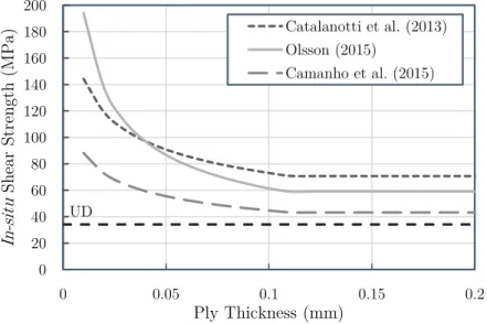
The application of 3D phenomenological failure criteria has been proposed to estimate and take into account the in-situ effect on the transverse shear and transverse compressive strengths of thin embedded plies [46; 47]. According to these models, when embedded in a multidirectional laminate, not only YTisand SLisare assumed in-situ properties (calculated using the models proposed by Camanho et al. [33]), but also YCis and STis.
Catalanotti et al. [46] proposed a 3D failure criteria, considering both longitudinal and transverse failure mechanisms, where the effect of ply thickness on the material strength is taken into account. Focusing on transverse compression failure, the proposed criterion is based on Puck’s criterion [70; 71], assuming a modified failure index, in order to take into account the in-situ effect. Considering pure transverse compression, starting from a modified failure index expression, STis is explicitly given as [46]:
STis= 1 2 (2 sin2(α0) − 1)SLis p 1 − sin2(α0) sin(α0)ηL (2.10) where α0 is the fracture angle under uniaxial transverse compressive failure and ηL is the
friction coefficient of the composite material [46].
Camanho et al. [47] developed 3D failure criteria based on the transversely isotropic yield function proposed by Vogler and co-authors [72; 73]. The referred criteria have
2. State-of-art and literature review
an invariant quadratic formulation based on structural tensors that account for the pre-ferred directions of the anisotropic material. With this formulation, the typical anisotropy present in FRPs is derived using structural tensors and not symmetric conditions based on a reference coordinate system. The so-called structural tensors represent the mate-rial symmetries of the respective anisotropy class as an intrinsic matemate-rial property, which enables an elegant coordinate system-free description of anisotropy using isotropic tensor functions. According to these criteria, the in-situ transverse shear strength and the in-situ biaxial transverse tensile strength are numerically calculated imposing [47]:
ηL(+)= ηL,is(+) ηT(+)= ηT,is(+) (2.11) where ηLand ηT are, respectively, the slopes in the σ22−σ12and σ22−σ23failure envelopes
when σ22= 0. Camanho et al. [47] assumed that ηL and ηT are not in-situ properties —
see Figure 2.9. Accordingly, solving the system of equations present in 2.11, the in-situ transverse shear strength can be written as [47]:
STis= SLisST SL (2.12) \ 0 50 100 150 200 250 300 -600 -400 -200 0 200 𝜎12 (MP a) 𝜎22(MPa) In-situ UD YCis L,is(-) L,is(+) L(-) L(+) SLis YTis SL YT YC
(a) σ22− σ12failure envelope.
0 50 100 150 200 250 300 -600 -400 -200 0 200 𝜎23 (MPa ) 𝜎22(MPa) In-situ UD T,is(+) T (-) T (+) YCis YC YT YTis STis T,is(-) ST (b) σ22− σ23 failure envelope.
Figure 2.9: Definitions of the parameters ηL and ηT (adapted from Camanho et al. [47]).
Olsson [48] proposed an analytical model for damage prediction due to large mass impact on thin-ply composites. He assumed that in multidirectional laminates, the STis is governed by the growth of transverse shear cracks, which typically appear as inclined mode I transverse shear cusps, sandwiched between two comparatively stiff plies and deflect into delaminations — see Figure 2.10. Similarly to constrained transverse plies loaded in tension, the constraining effect of the stiffer adjacent plies reduces the available elastic energy within the ply, delaying transverse shear crack growth in the matrix [14; 35–37]. According to the author, the in-situ transverse shear strength is given for a thick embedded ply as [48]:
STis = 1.12√2YT (2.13)
and for a thin embedded ply as [48]: STis= 1.4
s
GIcE2
2(1 + ν23)t
(2.14) where GIc is the intralaminar fracture energy in mode I, E2 is the transverse Young’s
modulus (perpendicular to the fibres direction), ν23is the transverse Poisson’s ratio of the
composite material, and t is the ply thickness. 18
2.2. Ply thickness scaling and its effect on composite laminates τ23
τ23
Figure 2.10: Transverse shear cracking scenario in multidirectional laminates (adapted from Olsson [48]).
A comparison of the predictions of the in-situ transverse shear strength of an embedded ply according to the criteria specified above can be seen in Figure 2.11. Some differences can be observed, but no direct or indirect validation is available yet for any of these criteria.
0 20 40 60 80 100 120 140 160 180 200 0 0.05 0.1 0.15 0.2 In -si tu Sh ear Str en gt h (MPa) Ply Thickness (mm) Catalanotti et al. (2013) Olsson (2015) Camanho et al. (2015) UD
Figure 2.11: Predictions for the in-situ transverse shear strength of a thin embedded ply.
In-situ transverse compressive strength
There is no direct experimental evidence of an in-situ effect in transverse compression. However, recent studies, which adressed directly or indirectly the effect of ply thickness on the compressive properties of multidirectional laminates, indicate that ply thickness affects the compressive response of polymer composite laminates [45; 74; 75].
Kawabe et al. [74] studied the thin-ply effects on the compressive properties of mul-tidirectional, quasi-isotropic composite laminates, by employing compression tests. Ply thicknesses starting from 0.045 mm were analysed. A clear in-situ effect in compression has been reported by the authors. Er¸cin et al. [45], reported a higher compressive un-notched strength for laminates having dispersed plies when compared to partially
![Figure 2.1: Schematic representation of a thin-ply and thick-ply morphology (adapted from [22]).](https://thumb-eu.123doks.com/thumbv2/123dok_br/19177858.943998/31.892.194.697.831.1030/figure-schematic-representation-ply-thick-ply-morphology-adapted.webp)

![Figure 2.4: Cracking strain of different glass fibre-reinforced polymer cross-ply laminates (adapted from Garrett and Bailey [40] and Parvizi et al](https://thumb-eu.123doks.com/thumbv2/123dok_br/19177858.943998/35.892.239.676.793.1077/figure-cracking-different-reinforced-polymer-laminates-garrett-parvizi.webp)
![Figure 2.5: In-situ effect on the transverse tensile strength of an embedded 90 ◦ ply (adapted from Flaggs and Kural [31]).](https://thumb-eu.123doks.com/thumbv2/123dok_br/19177858.943998/36.892.218.671.384.668/figure-effect-transverse-tensile-strength-embedded-adapted-flaggs.webp)
![Figure 2.6: In-situ transverse tensile strength of an inner 90 ◦ ply (adapted from Dvorak and Laws [32]).](https://thumb-eu.123doks.com/thumbv2/123dok_br/19177858.943998/37.892.218.674.140.427/figure-transverse-tensile-strength-inner-adapted-dvorak-laws.webp)

![Figure 2.14: Normalised crack length as a function of applied strain for different 90 ◦ ply thicknesses (adapted from Arteiro et al [15]).](https://thumb-eu.123doks.com/thumbv2/123dok_br/19177858.943998/49.892.239.673.141.430/figure-normalised-function-applied-different-thicknesses-adapted-arteiro.webp)
![Figure 2.16: COD as a function of applied strain for different 90 ◦ ply thicknesses (adapted from Arteiro et al [15]).](https://thumb-eu.123doks.com/thumbv2/123dok_br/19177858.943998/50.892.238.677.670.956/figure-function-applied-strain-different-thicknesses-adapted-arteiro.webp)