SPECIFICATIONS
Control, drive mechanism Inverter control, driven directly by motor Inverter control, driven directly by motor. External finish Pre-coated galvanized steel sheets (+ powder coating for -BS type) Pre-coated galvanized steel sheets (+ powder coating for -BS type). Heat exchanger Salt-resistant cross fin and copper tube Salt-resistant cross fin and copper tube.
HIC circuit (HIC: Heat Inter-Changer) Copper tube, tube-in-tube structure Copper tube, tube-in-tube structure. FAN Type x Number Propeller fan x 1 Propeller fan x 2 Propeller fan x 2. Control, Driving mechanism Inverter control, Directly driven by motor Inverter control, Directly driven by motor Inverter control, Directly driven by motor. High pressure sensor, high pressure switch at 4.15 MPa (601 psi) Inverter circuit (COMP./FAN) Overcurrent protection Overcurrent protection Overcurrent protection.
External finish Pre-coated galvanized steel sheets. powder coating for -BS type) Pre-coated galvanized steel sheets. powder coating for -BS type) Pre-coated galvanized steel sheets (+powder coating for -BS type). FAN Type x Quantity Screw Fan x 2 Screw Fan x 2 Screw Fan x 2. Control, Drive Mechanism Inverter Control, Direct Driven by Motor Inverter Control, Direct Driven by Motor Inverter Control, Direct Driven by Motor.
EXTERNAL DIMENSIONS
3 The length of the protruding part of the anchor bolt must not exceed 30 mm. (Figure A, B) 4 Use the six mounting plates as shown in the right figure
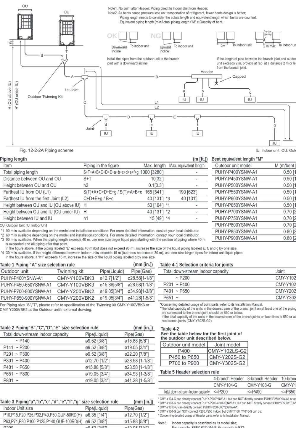
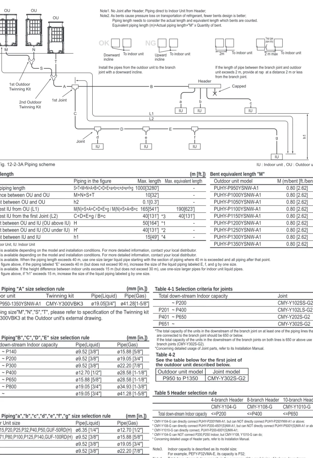
To indoor unit Liquid twin pipe
Outdoor unit 3 Double liquid pipe 1
CENTER OF GRAVITY
ELECTRICAL WIRING DIAGRAMS
HIC bypass, Controls coolant flow in HIC circuit For opening/closing the exhaust suction bypassSV2SV1aLEV2a,b. Symbol
Bypass HIC,Controls the coolant flow in the HIC circuit To open/close the exhaust suction bypass Tube temperatureSV2. 21S4aSymbol
CN3032121 LEV2d *9 Pressure control, coolant flow control Inverter heat exchangerLEV9 *9,10 For opening/closing the bypass circuit SV9 *8 For continuous heating SV10,11 *8 TH2 *8 Subcooled bypass output temperature Thermistor TH6 *8 Subcooled liquid coolant temperature. LED2 Normal operation (lit)/error (flashing) LED3 SW6-10 is OFF and SW4-1~10 are OFF During operation (lit)/idle (off) SW6-10 is ON Function setting with SW4 enable (lit)/disable (off) LED101Normal operation (on)/IC error (off) *8.Device difference.
SOUND LEVELS
Depending on operating conditions, the unit generates noise caused by valve actuation, coolant flow, and pressure changes when operating normally. The system can return to normal operation from low noise mode automatically in case the operating condition is severe. Depending on the operating conditions, the unit generates noise caused by valve actuation, coolant flow and pressure measurement.
VIBRATION LEVEL
OPERATION TEMPERATURE RANGE
CAPACITY TABLES
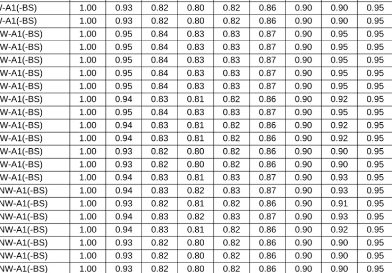
Outdoor unit capacity (CTo) = Rated outdoor unit capacity × (model size ratio). ck: Outdoor unit's power input coefficient for k indoor unit's room temp. Indoor Design Dry Bulb Temperature Correction (25ºC) 0.80 (See Fig.4) CTi = Σ (Indoor Unit Rating × Indoor Design Temperature Correction). Maximum System Capacity (CTx) = Total Outdoor Unit Capacity (CTo), so use the following formula PIo = Outdoor Unit Cooling Rated Power Input × Indoor Temperature Correction Coefficient.
Outdoor unit coefficient for indoor unit 1 (outdoor temp.. 25 °CD.B.) Outdoor unit coefficient for indoor unit 2 (outdoor temp. Due to frost on the outdoor heat exchanger and automatic defrosting, the heating capacity of the outdoor unit can be calculated by multiplying correction factor shown in the table below.
OPTIONAL PARTS
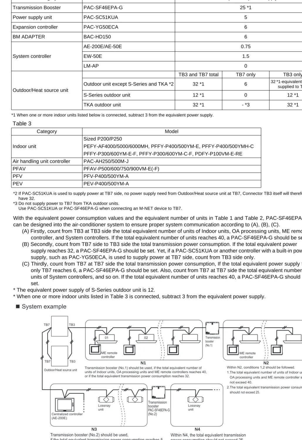
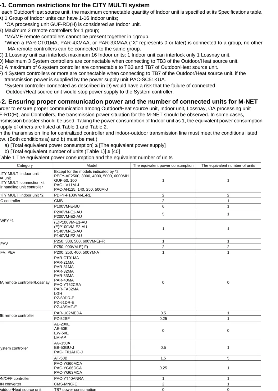
Depending on the importance of the system, separate the power supply system or get the protective coordination of the switches. 4 When the outdoor unit is connected to the system controller, power supply to TB7 of the outdoor unit(s) is required. The shield wire of the central control transmission cable must be grounded on the outdoor unit whose CN41 is changed to CN40.
Depending on the importance of the system, separate the power supply system or take protection coordination of circuit breakers. F) 4 or more system controllers can be connected by connecting to TB7 of the outdoor/heat source unit if the transmission power is provided by the power supply unit PAC-SC51KUA. When connecting to TB3 of the outdoor/heat source unit and receiving power from the outdoor/heat source unit.
When connecting to TB7 of an outdoor unit/heat source and receiving power from the outdoor unit/heat source. When connected to TB7 of an outdoor unit/heat source but receiving power from the PAC-SC51KUA. Connecting to TB7 of the outdoor unit/heat source, but receiving power from the PAC-SC51KUA power supply unit.
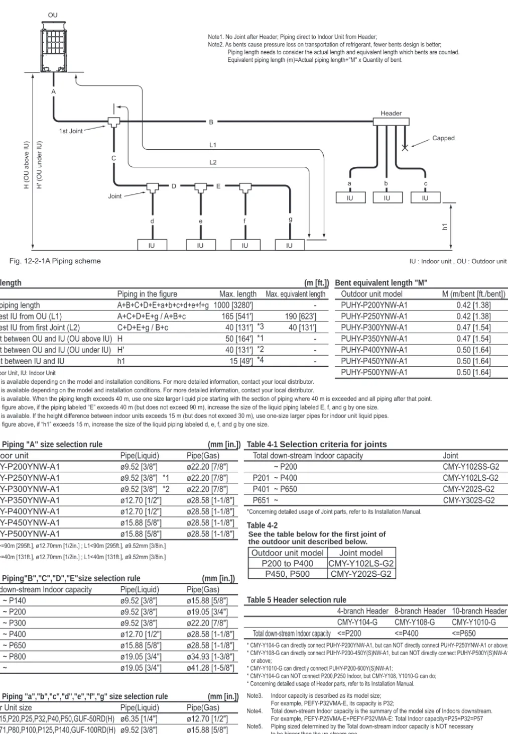
The total downstream internal capacity is the summary of the model size of the internal downstream capacity. In the figure above, if “h1” is greater than 15 m, increase the liquid line size labeled g by one size. In the figure above, if “h1” is greater than 15 m, increase the liquid line size labeled g by one size.
Total downstream Indoor capacity is the summary of the model size of Indoor downstream. Calculate the amount of additional charge based on the length of the pipe extension and the size of the coolant line. Front/Right/Left/Rear Same height or lower than the overall height of the unit.
Install the unit so that the corner of the angle bracket at the bottom of the unit shown in the illustration is securely supported. Install the unit so that the corner of the angle bracket at the bottom of the unit shown in the figure below is securely supported.
Installation information
The return air temperature display on the remote control may differ from that on the other thermometers. The clock on the remote control can be displayed with a time delay of about one minute every month. The temperature used by a built-in temperature sensor on the remote control may differ from the actual room temperature due to the effect of the wall temperature.
Use the built-in thermostat on the remote control or the thermostat sold separately when ceiling or in-ceiling indoor units operate automatic cooling/heating switching. If the unit is installed on an upper floor or in a high temperature and high humidity environment, thicker insulation may be required. The AUTO mode on the local remote controller is only available when the fresh air supply indoor unit is connected to the R2 or WR2 series outdoor unit.
Depending on the load of the air conditioning system, the outside temperature and due to the activation of protection functions, the outlet temperature may fluctuate. It is not recommended when the fresh air intake type indoor unit is connected to the Y or WY series. Depending on the load of the air conditioner, the outside temperature and due to the activation of protection functions, the desired preset temperature may not always be achieved and the outlet temperature may fluctuate.
When the snow accumulates approximately 50 cm or more on the snow guard, remove the snow from the guard. Install a strainer (50 mesh or more recommended) on the water pipe inlet of the heat source unit. When Thermo ON and OFF are repeated frequently on the indoor unit, the operation status of outdoor/heat source units may become unstable.
The temperature sensors that register a room temperature are installed on both the remote control and the indoor unit. When a room temperature is detected using the sensor on the remote control, the main remote control is used to detect a room temperature. If a room with a total opening area of more than 0.15% of the floor area is in a low position with another room/spaces, the two rooms/spaces are considered as one. The total space is added together.