U Patch Antenna using Variable Substrates for
Wireless Communication Systems
Saad Hassan Kiani
1, Khalid Mahmood
2, Umar Farooq Khattak
3, Burhan-Ud-Din
4, Mehre Munir
5 Electrical Engineering Department1,4,5Computer Science Department3
City University of Science and Information Technology1,3,4,5, Member IEEE2 Peshawar, Pakistan
Abstract—Due to their smaller size and light weighted structures patch antennas are frequently now used in GPS transmitters and receivers and throughout modern communication technology. In this paper a miniaturaized patch antenna is presented using stack configuration. Various parameters such as gain, directivity, return loss, efficiency of antenna is demonstrated. Using Air, Teflon, Foam and FR4 (Lossy) as substrates FR4 (lossy) is kept fixed and other substrates are combined one by one to observe response of proposed antenna. The antenna showed dual and tri band response with different combination of mentioned substrates. The proposed antenna has been found useful for W-LAN, GSM, Radio Satellite, Fixed Satellite Services (RSS) & (FSS) and satellite communication systems.
Keywords—miniaturization; directivity; gain; substrates; efficiency; VSWR; Wireless communication; Multiband response
I. INTRODUCTION
With rapid advancement in communication technology, patch antenna miniaturization and multiband response has attracted researchers and designers to involve. Applications of such patch structures embrace but not bounded to personal, military applications, vehicular communication and much more. As traditional antenna offers complex and low gain structures with difficult and long process fabrication, patch antennas have been known due to their ability of easy fabrication and light weighted structures. As Multiband
response is necessity of today’s communication era, different
methodologies and process have been introduced. Some of them are mentioned below.
Only low amount of size reduction was achieved with use of split ring resonators [1-2].Using H-Shape on ring antenna showed multivariable response but bandwidth and gain reduced to significantly low levels [3]. With reverse outcome of declination of radiation pattern and poor antenna bandwidth, by aggregating electric permittivity of a substrate antenna size is reduced [4]. With high increase of cost and fabrication, metamaterials have been found useful in reducing size of patch [5-6]. Expenditure of synthetic magnetic conductors resulted with lowered gain at desired resonant frequencies [7]. With fluctuating return loss plot and poor radiation pattern in [8] defected ground structure resulted in reducing 30% size and dual band response. Hence in simple words patch size reduction and multi band response has been a very common interesting topic among researchers [9-11].
Upper substrate play a vital role in resulting various antenna parameters [12]. Therefore in this paper we have proposed a multiband patch antenna using stack configuration. By use of Air, Teflon PTFEE and Foam with fix FR4 (lossy) as substrate, different parameters response has been observed. Computer Simulation technology 2014 has been used for designing and modeling of proposed design.
This paper is organized as follows:
Section I deals with introduction, Section II shows antenna Structure, Section III includes detailed result analysis and Section IV includes Conclusion.
II. ANTENNA DESIGN
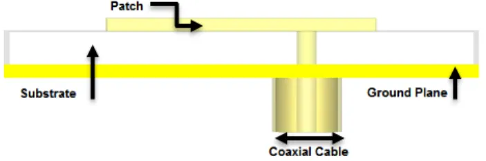
The elementary patch antenna comprises of patch, substrate and ground plane as shown in fig 1.
Fig. 1. Elementarypatch antenna
A. Substrate
The first significant charge while scheming an antenna is selection of a proper substrate with proper dielectric constant as various parameters are linked up to substrate. In projected antenna design, due its cost success, dampness enduring competences, FR4 (lossy) is chosen as first and basic substrate with dielectric constant of 4.3. Air, Teflon and Foam are chosen as second substrates to observe antenna behavior.
B. Width
For calculating and deriving patch width following equation is used. (1).
√
C. Length
In order to derive Patch length, following equation is used. (2).
Where
√
And
Where h is the height and W as mention above is the patch width. Antenna with resonating frequency of 4.5GHz is designed by calculating patch dimensions.
Various dimensions of the proposed antenna technique are provided in table 1.
TABLE I. DIMENSIONS OF PROPOSED ANTENNA
Parameters Values in MM
Patch Length, PL 16.11
Patch Width, PW 21.43
Ground Length, GL 28.11
Ground Width, GW 33.43
Vertical Fractal Slot Length,
VFSL 10.0
Vertical Fractal Slot Width,
VFSW 4.0
Horizontal Fractal Slot Length
,HFSL 8.0
Horizontal Fractal Slot Width,
HFSW 4.0
U Slot Length, UL 6.0
U Slot Width, UW 1.0
Patch Height, PH 0.0035
Height of Ground, HG 0.08 Height of First Substrate, HS 2.0 Height of Second Substrate,
H2S 1.0
Horizontal U and H Slot
Width, HUW&HHW 1.0 Horizontal U Slot Length,
HUL 8.0
Horizontal H Slot Length, HHL 7.0 Vertical U and H Slot Length,
6.0 VUL&VHL
Vertical U and H Slot Width, 1.0 VUW &VHW
After designing patch antenna for 4.5 GHz, fractal shape is implemented as following.
Patch is slotted by 8mm length and 10mm width horizontally and 10mm length and 4mm width vertically. U shape slot on fractal patch is designed with the following dimensions as shown in Fig 2. Length of slot is 6mm and width of the slot is 1mm.Now to further reduce size and for efficient frequency response defected ground structure
technique is used by adding U and H slot on a ground plane as shown in fig 2.
Fig. 2. (a) Frontal View of Patch with single Substrate (b) Frontal View of Ground
The antenna is fed by Co-axial cable a contacting scheme in which inner conductor is mounded to patch through hole from ground through substrate while outer conductor connected with ground plane.
Figure 2 shows the frontal view of single patch antenna. The second layer of antenna with different combinations is shown in Figure 3 and 4.
Fig. 3. Overall view of Stacked antenna
Fig. 4. (a) Front View of Patch antenna with Roggers (b) Front view of Patch antenna with Foam (c) Front view of Patch antenna with Air
The propsed antenna showed unlike response interms of gain, directivity, radiation patterns and bandwidth. Results are disscussed one by one.
III. RESULTS AND DISSCUSSIONS
After simulation, we got the following results in Return loss graph showing tri band response but this return loss is
only of single substrate that’s is FR4 (lossy) as first base
From taking a look at return loss graph we have got tri band response. For 3.349 we have got -12.05dB return loss. For frequency 4.7GHz we have got good return loss of -34.47dB and in the end we have got resonating frequency having return loss exceeding -24dB.
Fig. 5. Return loss graph of antenna
The impedance smith chart of proposed patch is shown below.
Our proposed antenna is operating at fixed impedance of 50 ohm hence showing antenna is fed accurately by Coaxial cable.
Fig. 6. Smith chart view of proposed antenna
In single patch results, all the radiation pattern showed great patterns for all the resonating frequencies.
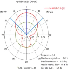
Fig. 7. 1D radiation pattern of Gain at 3.349GHz
Fig. 8. 1D radiation pattern of Directivity at 3.349GHz
For 3.349 GHz single patch, the magnitude of main lobe scale is 2.91dB, main front lobe direction is 0 degrees and angular width is 96.8 degrees while back lobe scale is -5.5dB.
For directivity plot, the main front lobe scale is 5.64dBi, main lobe direction is 0.0 degrees and angular width is 96.8 degrees while back lobe scale is -5.5dB. The Radiation patterns are shown in Fig 7 and 8.
As our main concern is stack configuration patch analysis, hence we will mainly focus on stacked patches result. These cases are discussed one by one.
A. Air
Air can be seen as substrate in various patch designs, the first combination with FR4 (lossy) was chosen to be air. Following values were obtained.
TABLE II. PARAMETER RESULTS WITH OF AIR
Frequency Return Loss Gain Directivity Bandwidth
3.32GHz -12.49dB 3.02dB 5.7dBi 60MHz
6.32GHz -24.10dB 2.87dB 5.74dBi 200MHz
Return loss Values obtained were -12 and -24 respectively at 3.3 and 6.32GHz. Radiation pattern of fundamental (first) resonant frequency is shown in figure 9 and figure 10.
For 3.349GHz, the magnitude of main lobe scale is 3.02dB, main front lobe direction is 0 degrees and angular width is 95.8 degrees while back lobe scale is -5.5dB.
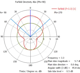
Fig. 10.1D radiation pattern of Directivity at 3.3GHz
For directivity plot, the main front lobe scale is 5.7dBi, main lobe direction is 0.0 degrees and angular width is 95.8 degrees while back lobe scale is -5.5dB.
So overall of gain increase from 2.9 to 3.02 was seen to be increase with Air as compared to single patch.
The VSWR of proposed antenna showed good results for all resonating frequencies as all values were less than 2 with near to approximately null Mismatch loss.
Formula used for calculating VSWR is shown in eq 5.
| |
| |
Where |r| is the reflection coefficient also called return loss.
By inverting the formula in eq (5), reflection coefficient |r| can also be determined.
| |
Now the reflection coefficient obtained in eq (6) is in voltage to actually know the amount of reflected power following equation is used.
| |
And
| |
Where in eq (7) reflected power is obtain in percentage and through eq (8) is obtained in dBIn last power is conveyed or reflected from antenna. Amount of power being lost from antenna is due to mismatch of impedance.
| |
All the above mention parameters were calculated for proposed antenna. The approximate values are shown in the following table.
TABLE III. VSWRVALUES OF RESONANT FREQUENCIES
Resonant
Frequency VSWR
Reflection Coefficient
Reflected Power (%)
Reflected Power (dB)
Mismatch Loss (dB)
3.3GHz 1.63 0.24 5.7 -12.41 0.26
6.1GHz 1.10 0.05 0.2 -26.44 0.01
From results shown in table III all the resonant frequencies prove that antenna impedance is matched. For 3.3GHz antenna power delivered is up to 80% and for 6.1GHz power radiated is nearly 99.99%.
B. Foam
Second substrate to be combined was chosen to be foam as due to its low permittivity values, ease of availability and ease of fabrication. Following results were observed.
TABLE IV. PARAMETER RESULTS WITH FOAM
Frequency Return Loss Gain Directivity Bandwidth
3.33GHz -12.71dB 2.99dB 5.64dBi 60MHz
4.88GHz -10.17dB 0.78dB 5.99dBi 30MHz
6.32GHz -29.41dB 3.42dB 5.98dBi 200MHz
Return loss obtained were -12, -10 and -25dB at respective resonant frequencies of 3.3, 4.8 and 6.3GHz. Radiation pattern were good with minor back lobe radiation. The first resonant frequency of 3.3GHz radiation patterns of gain and frequency are shown in fig 11 and fig 12.
Fig. 11.1D radiation pattern of gain at 3.3GHz
Fig. 12.1D radiation pattern of Directivity at 3.3GHz
For directivity plot, the magnitude of main lobe scale is 5.64dBi, main front lobe direction is 0 degrees and angular width is 96.5 degrees while back lobe scale is -5.4dB.
So overall of parameters results of foam were observed to be very similar to that of air substrate results with minor changes.
The VSWR of proposed antenna showed good results for all resonating frequencies as all values were less than 2 with near to roughly null Mismatch loss.
TABLE V. VSWRVALUES OF RESONANT FREQUENCIES
Resonant
Frequency VSWR
Reflection Coefficient
Reflected Power (%)
Reflected Power (dB)
Mismatch Loss (dB)
3.3GHz 1.63 0.23 5.3 -12.41 0.26
4.8GHz 1.8 0.29 8.2 -10.08 0.37
6.1GHz 1.07 0.03 0.1 -29.42 0.01
From results shown in table V all the resonant frequencies prove that antenna impedance is matched. For 3.3GHz antenna power delivered is up to 85%. For 4.8GHz, power is delivered round about 70%. And at last for 6.1GHz power radiated is nearly 99.98%.
C. Teflon
With relative permittivity of 2.1, Teflon was chosen as third substrate with FR4 for stack configuration. Following parameter results were observed.
TABLE VI. PARAMETER RESULTS WITH TEFLON
Frequency Return Loss Gain Directivity Bandwidth
3.2GHz -11.74dB 2.68dB 5.45dBi 50MHz
4.7GHz -15.56dB 1.34dB 5.32dBi 90MHz
6.1GHz -17.95dB 3.67dB 6.34dBi 200MHz
Return loss obtained were -11, -15 and -17dB at respective resonant frequencies of 3.2, 4.7 and 6.1GHz. Radiation pattern were good with minor back lobe radiation. The first resonant frequency of 3.2GHz radiation patterns of gain and frequency are shown in fig 13 and fig 14.
Fig. 13.1D radiation pattern of gain at 3.2GHz
For 3.3GHz, the magnitude of main lobe scale is 2.68dB, main front lobe direction is 0 degrees and angular width is 98.0 degrees while back lobe scale is -5.0dB.
Fig. 14.1D radiation pattern of Directivity at 3.2GHz
For directivity plot, the magnitude of main lobe scale is 5.45dBi, main front lobe direction is 0 degrees and angular width is 98.0 degrees while back lobe scale is -5.0dB.
With Teflon substrate, for fundamental resonant frequency of 3.2GHz, gain was observed to be less than that of air and foam but overall radiation pattern, directivity and other VSWR parameters were as food as air and foam. The VSWR values are shown in table VII.
TABLE VII. VSWRVALUES OF RESONANT FREQUENCIES
Resonant
Frequency VSWR
Reflection Coefficient
Reflected Power (%)
Reflected Power (dB)
Mismatch Loss (dB)
3.32GHz 1.7 0.26 6.7 -11.71 0.3
4.7GHz 1.02 0.17 2.8 -15.56 0.12
6.1GHz 1.10 0.13 1.6 -17.95 0.07
For 3.2GHz antenna power delivered is up to 94.3%. For 4.7GHz nearly all the power is delivered from transmitter side. And at last for 6.1GHz power radiated is nearly 99.3%.
The antenna after size reduction resonated with fundamental frequency of 3.3GHz. The fundamental antenna with resonant frequency of 3.3GHz would require dimensions of 27.94×21.30=594.6 where it was obtained with only dimensions of 16x21= 361mm² hence reducing the size up to 60%. It was also observed that with use of stack configuration different substrates exhibit different behavior of resonant frequencies. Higher the permittivity lower the resonant frequency as in case of Teflon fundamental frequency was down to 3.2 hence resulting in size reduction up to 57% but with expense of lower performance of antenna parameters.
IV. CONCLUSION
In this paper, U shaped patch antenna with stack configuration was presented. With use of multiple substrates antenna exhibited different result. It was concluded that through stack configuration using higher permittivity substrates results in more size reduction with expanse of degradation if antenna performance parameters but with mentioned three combinational substrates proposed antenna is very useful and can be used for W-LAN, GSM, Radio Satellite, Fixed Satellite Services (RSS) & (FSS) , W-LAN and Satellite communication system applications.
V. FUTURE WORK
This design can be implemented on multiple input multiple output (MIMO) technique to observe more enhance radiation response. Meanwhile by insertion of Electromagnetic band gap (EBG) structures more focused radiation pattern can be concluded with reduction in electromagnetic interaction in MIMO implementation.
ACKNOWLEDGMENT
The author would acknowledge the environment and support provided by City University of Science and Information Technology Peshawar, Pakistan.
REFERENCES
[1] Shaw, Tarakeswar, Deepanjan Bhattacharjee, and Debasis Mitra. "Miniaturization of slot antenna using split ring resonators." Applied Electromagnetics Conference (AEMC), 2015 IEEE. IEEE, 2015.
[2] Liu, Yanxia, et al. "A miniaturized artificial magneto-dielectric resonator antenna with split ring resonators." Antenna Technology and Applied Electromagnetics (ANTEM), 2016 17th International Symposium on. IEEE, 2016.
[3] Liu, Y., Shafai, L. and Shafai, C., 2016, July. Gain and bandwidth enhancement of stacked H-shaped patch-open ring antenna. In Antenna Technology and Applied Electromagnetics (ANTEM), 2016 17th International Symposium on (pp. 1-2). IEEE.
[4] Yuan, Bo, et al. "An axial‐ratio beamwidth enhancement of patch antenna with digonal slot and square ring." Microwave and Optical Technology Letters 58.3 (2016): 672-675.
[5] Dai, Yuanlong, et al. "Ultra-wideband patch antenna with metamaterial structures." 2015 IEEE 16th International Conference on Communication Technology (ICCT). IEEE, 2015.
[6] Yuan, Hang‐Ying, et al. "A metamaterial‐inspired wideband high‐gain FABRY–Perot resonator microstrip patch antenna." Microwave and Optical Technology Letters 58.7 (2016): 1675-1678.
[7] Rahmadani and A. Munir, "Microstrip patch antenna miniaturization using artificial magnetic conductor," in Telecommunication Systems, Services, and Applications (TSSA), 2011 6th International Conference on, 2011, pp. 219-223.
[8] Saad Hassan Kiani, Shahryar Shafique Qureshi, Khalid Mahmood, Mehr-e- Munir and Sajid Nawaz Khan, “Tri-Band Fractal Patch Antenna for GSM and Satellite Communication Systems” International Journal of Advanced Computer Science and Applications(IJACSA), 7(10), 2016. [9] Ren, Wang, and Chen Jiang. "A novel design of multiband printed
anchor‐shaped slot antenna." Microwave and Optical Technology Letters 58.3 (2016): 521-526.
[10] Munir, Mehre-E., Ahsan Altaf, and Muhammad Hasnain. "Miniaturization of microstrip fractal H-Shape patch antenna using stack configuration for wireless applications." Recent Trends in Information Systems (ReTIS), 2015 IEEE 2nd International Conference on. IEEE, 2015.
[11] Caporal Del Barrio, Samantha, Art Morris, and Gert F. Pedersen. "Antenna miniaturization with MEMS tunable capacitors: techniques and trade-offs." International Journal of Antennas and Propagation 2014 (2014).
[12] Kiani, Saad Hassan, Khalid Mahmood, Sharyar Shafeeq, Mehre Munir, and Khalil Muhammad Khan. "A Novel Design of Miniaturaized Patch Antenna Using Different Substrates for S-Band and C-Band Applications." INTERNATIONAL JOURNAL OF ADVANCED COMPUTER SCIENCE AND APPLICATIONS 7, no. 7 (2016): 273-278.
[13] Fakharian, Mohammad M., et al. "A capacitive fed microstrip patch antenna with air gap for wideband applications." International Journal of Engineering, Transactions B: Applications 27.5 (2014): 715-722. [14] Altaf, Ahsan, and Syed Imran Hussain Shah. "Miniaturization of