www.geosci-instrum-method-data-syst.net/5/551/2016/ doi:10.5194/gi-5-551-2016
© Author(s) 2016. CC Attribution 3.0 License.
About the possibility of identification of hydrocarbon
deposits with the help of NMR
Pavlo M. Ivashchenko, Eduard A. Bakai, and Alexander I. Yurchuk
Institute Geophysics and Problems of the Earth Ltd., Kiev, 01014, Ukraine
Correspondence to:Pavlo M. Ivashchenko ([email protected]) and Alexander I. Yurchuk ([email protected]) Received: 10 March 2016 – Published in Geosci. Instrum. Method. Data Syst. Discuss.: 12 May 2016 Revised: 16 October 2016 – Accepted: 6 November 2016 – Published: 30 November 2016
Abstract. The main purpose of this article is to review the theoretical prerequisites of nuclear magnetic resonance (NMR) application in tasks of search and exploration of hy-drocarbon deposits. The identification peculiarities of hydro-carbon deposits in a weak magnetic field of the Earth were analysed. The necessity of using highly directional antennas for providing greater sounding depths as well as the use of absorption spectra of the sought-for minerals as sounding signals were identified and justified. A variant of practical implementation of such a system was examined and exam-ples of practical application of the innovative NMR technol-ogy were provided.
1 Introduction
Nuclear magnetic resonance (NMR) is a phenomenon of res-onant absorption and reradiation of radio-frequency electro-magnetic energy by substance with non-zero electro-magnetic mo-ments of nuclei in an external constant magnetic field. Non-zero nuclear magnetic moment have nuclei1H,2H,13C,14N, 15N,19F,29Si and31P, among others.
At the moment it is difficult to specify a field of natural sciences which would not use NMR to some extent.
NMR methods are widely used in chemistry, molecular physics, biology, medicine and related sciences – that is where the study of substance makeup and its molecular struc-ture is required.
In physics NMR has introduced unique information on thermodynamics of spin systems, localization and mobility of nuclei, atomic groups and molecules in crystal lattice. In chemistry NMR has introduced information about the struc-ture and dynamic stereochemistry of many important classes
of compounds, exchange processes, etc. Effective analytical and structural–chemical methods for medicine, biochemistry, pharmacology and chemical industry were developed on this basis.
NMR has found its place in applied geophysics in the creation of magnetometers for magnetic survey (Hill, 1960; Nalivayko et al., 1962). Of particular note is the spin-echo method, which allows us to determine the process speed of spin–lattice processes and spin–spin interactions. Imaging log (MRIL) was introduced in 1991 by NUMAR (Coates et al., 1991) based on the method of magnetic resonance. Hal-liburton and Schlumberger have created NMR logging de-vices, which are successfully used for logging of oil wells.
Radio-frequency impulses are sent to a reservoir in the process of NMR logging and between them the decline of response is measured from those of hydrogen protons, which entered into resonance at a given magnetic field. Here, in fact, the method of “direct” survey of reservoir characteris-tics conducted in the wellbore is used.
In accordance with Coates et al. (1992), NMR logging uses the idea of NMR imaging that was originally imple-mented in medical magnetic resonance imaging (MRI). In MRI the object is placed inside the device, and in NMR log-ging it is done vice versa: the device is placed inside the ob-ject – in a wellbore.
– Another issue is that the chemical composition of the oil is incomparably more complex than that of wa-ter. According to Pokonova et al. (1984), oil is a mixture of circa 1000 individual substances, most of which are liquid hydrocarbons (> 500 substances), sul-fur compounds (about 250 substances), nitrogen com-pounds (> 30 substances), oxygen comcom-pounds (about 85 substances) and organometallic compounds (vana-dium, nickel and others). Other components are dis-solved hydrocarbon gases, water, mineral salts (mainly chlorides), solutions of salts of organic acids, mechan-ical admixtures, etc. Therefore, the resonance excita-tion by one sinusoidal frequency is a rather unreliable method.
– By exciting all fluid protons, it is difficult to distinguish relaxation of oil and water in the Earth’s magnetic field. Moreover, NMR will be carried out in a relatively weak mag-netic field of the Earth. The average field density on the surface of the Earth is approximately 5×10⁻⁵T, which is significantly less than the power of magnets for NMR spec-troscopy.
Each of these factors is essential and requires its own anal-ysis for the formation of scientific and technical approach to implementation of the direct method of identification and survey of hydrocarbon deposits from the surface of the Earth. Let us consider first the theoretical background of NMR implementation in conditions listed above.
2 Theoretical background of remote sounding of interior using NMR
Nuclear magnetic resonance is one of the main methods of quantum physics. Primarily magnetic resonance methods in-clude NMR, electronic paramagnetic resonance (EPR) and nuclear quadrupole resonance (NQR). These methods pro-vide unique information for physicists and chemists about molecular structure and properties of substances and are powerful diagnostic methods in modern medicine.
NMR discovery became possible thanks to the fact that ex-istence of magnetic moments in many nuclei was experimen-tally established, which was predicted by Wolfgang Pauli back in 1924 with an explanation of hyperfine structure of atomic spectra (Pauli, 1924).
Transitions between the sublevels of Zeeman splitting due to interaction of the summary nuclear magnetic moment with
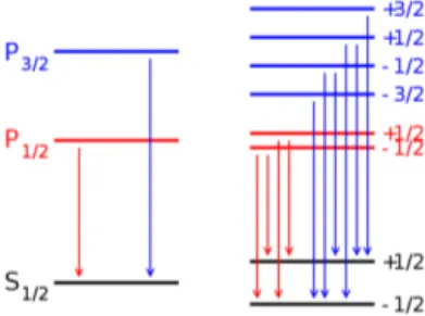
Figure 1.Example of the Zeeman effect for alpha transition in Ly-man series. On the left are unperturbed levels. On the right are levels split under the impact of magnetic field. The arrows indicate dipole allowed transitions.
external magnetic field were observed for the first time in 1938 by Isidor Rabi.
In 1946 two groups of American physicists from Stan-ford and Harvard universities led by Felix Bloch (Bloch, 1946) and Edward Purcell (Parcell, 1946) discovered the phenomenon of NMR in condensed matters. Later, in 1950, H. Dehmelt and H. Krueger received NQR signals. Shortly after, double spin–spin, photonic and spin-phononic resonances were developed.
As a result of these outstanding achievements in the field of NMR and EPR obtained by scientists from different coun-tries, there are a number of tried-and-true methods for study of nuclear relaxation, molecular structure, etc.
Rapidly developing method of NMR spectroscopy has be-come multi-nuclei providing the ability of analysis on all magnetic nuclei of the D. Mendeleev’s element periodic ta-ble. In this case information about the nucleus of this type is extremely accurately associated with intra- and intermolecu-lar structural and dynamic situations.
The important factors for our consideration that shape the unique resonance absorption spectra of substances are the Zeeman effect and the so-called “chemical” shift.
The Zeeman effect (Pieter Zeeman was a Dutch physi-cist who received the Nobel prize for his discovery in 1902) is the split of lines of atomic spectra in a magnetic field (Fig. 1). The resulting absorption spectrum of a substance is significantly enriched with new components while combin-ing atoms into molecules. The number of lines in the NMR spectrum is determined by the amount of chemically non-equivalent nuclei of this grade and constants of spin–spin in-teraction of these nuclei.
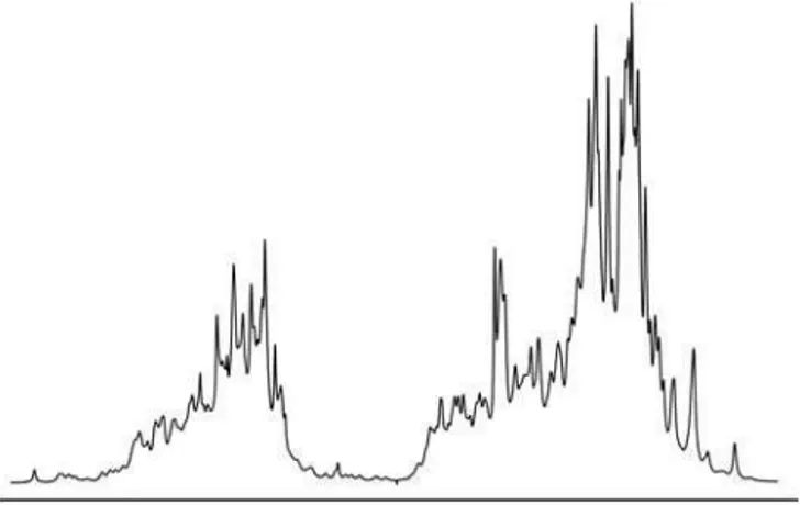
Figure 2.NMR absorption spectrum by protein molecule.
Chemical shift in NMR is an NMR signal bias dependent on chemical composition of substance due to shielding of an external magnetic field by electrons of atoms.
The phenomenon of chemical shift was originally discov-ered in 1951 in ethanol spirit CH3CH2OH. The phenomenon of separate resonance of protons contained in the molecule of the substance was obtained; that is, protons have different frequencies of own NMR in various substances. The same atomic nuclei in various environments in molecule show dif-ferent NMR signals.
Thus, the chemical shift reflects the chemical composi-tion of molecules. As the molecules become more complex, the total number of lines of the absorption spectrum will in-crease; if we take such a complex molecule as protein, then the spectrum will appear as qualitatively shown in Fig. 2.
Something similar will also occur for an aggregate of molecules forming crude oil.
3 Peculiarities of NMR in the magnetic field of the Earth
NMR is usually observed in a uniform constant magnetic field, onto which a weak radio-frequency field is superim-posed that is perpendicular to the constant magnetic field.
The main requirements of any NMR method to a source of constant magnetic field are magnetic field stability in time and high uniformity within the surveyed object.
Due to the fact that the artificially created magnetic field decreases rapidly with increase of distance from magnets, the research is carried out in strong magnetic fields of tens of thousands of gauss (Gs) in order to maintain the constancy of its value within the studied sample. The use of strong mag-netic fields for securing NMR entails the need to increase the capacity and frequency of the exciting (sounding) radio signal.
The main difference among the surveys in the Earth’s mag-netic field is a very weak field of circa 0.5 Gs. However, a big
Figure 3.Arrangement on location of MRS equipment of IRIS In-struments.
advantage here is its high stability and uniformity, as well as, undoubtedly, full accessibility and “free of charge” use of the natural magnetic field. In addition, to work in weak magnetic fields does not require a high-power radio signal.
The stability and uniformity of a magnetic field inside the Earth are particularly important for underground objects in-cluding deposits of hydrocarbons, which in terms of NMR are gigantic objects. For example, oil deposit with volume of 1 mln m3exceeds the “grain” of survey in MRI by 1015times, and thus is it impossible to create a stable uniform magnetic field within it.
It should be noted that to date there are a significant num-ber of publications on the NMR method in the Earth’s field. Among the first ones are works by M. Packard and R. Varian (Packard and Varian, 1953, 1954). A number of publications in this area have been summarized in monographs (Derome, 1992; Pukhliy and Kovalyov, 2010).
A particularly important example of practical implemen-tation of NMR in geophysics are the so-called MRS systems – systems to search for underground aquifers with the help of NMR.
Such systems operate at relatively shallow depths, up to 100–150 m, and have not yet been adapted to identify hydro-carbons occurring at much greater depths.
In this regard, we shall consider the operating principle of MRS systems and identify the factors that limit their appli-cability to work with hydrocarbons.
4 Operating principle and characteristics of MRS systems
The method of MRS is based on excitation, registration and mathematical processing of signal of nuclear magnetic reso-nance of protons of free water in the Earth’s magnetic field.
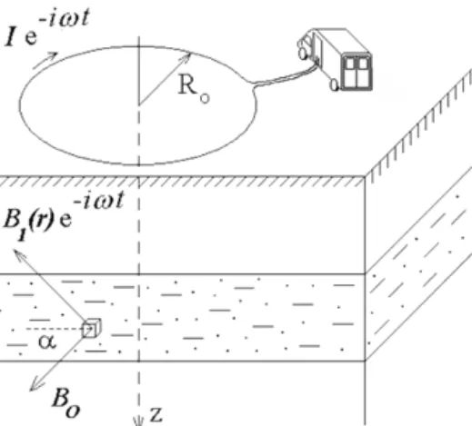
A special cable is used as an antenna for excitation and reception of a signal. The cable is placed on the ground sur-face in the shape of a square (NUMISPoly set by IRIS In-struments; Fig. 3) or circumference (hydroscope device by SibAkademTechnologies; Fig. 4).
Figure 4.Arrangement on location of MRS hydroscope.
gives information about the presence of water in the mea-surement area.
Pulse power of MRS transmitter is enormous. For exam-ple, in NUMISPolydevice impulse voltage of radio-frequency signal reaches 4000 V at current of 600 A. At the same time sounding depth does not exceed 150 m.
It is explained by the fact that MRS systems use ex-tremely inefficient antennas belonging to the type of wire low-hanging loop antennas. The main radiation of such an-tennas is directed to the zenith, but not in the direction of the object. Directionality of such antennas is shown in Fig. 5.
In radio, such antennas are used for ionosphere communi-cation in accordance with a maximum energy radiation in the vertical plane. Low-hanging antennas do not radiate into the ground (Gant= −60 dB) and the transmitter power is wasted. A similar pattern can be observed when the same antennas are used for receiving signals: useful signals are perceived poorly, but atmospheric interference successfully enters the input of the receiver.
5 The main problems of deep detection of hydrocarbons using NMR and their solutions
The first question that arises from experts while getting acquainted with this subject is the following: what power should the transmitter of radio signals have for resonance ex-citation of hydrocarbons, the deposits of which are located at a depth of, for example, 5 km.
Let us analyse the underground energetics of radio path. The path of underground sounding of hydrocarbon de-posits consists of two areas:
– ground surface–surveyed object – surveyed object–ground surface.
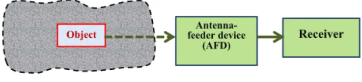
Radio transmitting equipment (RTE) is “responsible” for the first area (Fig. 6) and radio receiving equipment (RRE) for the second one (Fig. 7).
Figure 5.Directionality of low-hanging horizontal loop antenna.
Signal propagation medium
Object Transmitter feeder device
Antenna-(АFD)
Figure 6.Radio transmitting equipment.
RTE’s objective is to create an electromagnetic field con-centrated in the direction of the object. The effectiveness of this task implementation is determined by the energy flux density produced by RTE and directed toward the object per unit of time (module of Poynting vector) (Salamatin and Afonin, 2008):
|S| =PtransηAGant/ SA, (1) wherePtransis transmitter power,ηAis the coefficient of ef-ficiency of antenna feeder,Gantis the coefficient of antenna power gain andSAis the effective antenna area.
Figuratively speaking, the Poynting vector shows where and how much energy is transferred by electromagnetic wave.
We shall estimate the energy efficiency of MRS sys-tems. For this we shall use the system parameters of NUMISPoly: transmitter parameters areUtrans=4000 V and
Itrans=600 A.
We shall assume feeder efficiency for calculation simplifi-cation asηA=1.
Coefficient of antenna power gain in vertical downward direction in accordance with Fig. 5 is−60 dB, i.e. 10−6.
Effective area of loop antenna SA in accordance with (Markov and Sazonov, 1975) is equal to (0.7–0.9)L2, where
L=150 m is a side of rectangular loop antenna. We shall set the average value ofSA=0.8L2.
By substituting these values in Eq. (1), we obtain the effi-ciency of the systemE1:
E1= |S|1=4000×600×10−6/0.8×1502
=0.133×10⁻³Wm−2. (2)
Antenna-feeder device
(АFD) Receiver
Object
Signal propagation medium
Figure 7.Radio receiving equipment.
About the same pattern is observed on the receiving path. The same loop antenna used for reception weakens the useful signal and intensely receives noise from the radio.
Altogether despite the immense impulse power of the transmitter, as well as the use of receivers with low own noise, survey depth does not exceed h1=150 m. We shall now determine the power density of signalsE2, which should develop RTE for sounding at depths of up to 5 km.
We shall use for this the obtained MRS system characteris-tics and extrapolate them to calculate the required efficiency of RTE:
E2=f (h1, h2)·E1, (3)
wheref(h1,h2) is function from the depth of MRS sounding and required sounding depths of hydrocarbonsh2.
To construct the functionf (h1,h2) we shall take into ac-count the effects of scattering and absorption of radio waves in the propagation medium (Salamatin and Afonin, 2008):
– power of electromagnetic radiation in free space de-creases inversely as the distance square, i.e. Ps∼1/ h22; – loss in the medium increases proportionally to the
dis-tance, i.e. Ps∼1/ h2.
As a result we receive signal loss Ps∼1/ h32 and f(h1,
h2)=(h2/ h1)3.
Thus, in order to sound an area at a depth of up to
h2=5 km we need to ensure that the power density of the signal emitted in the direction of underground objects is equal to
E2=f (h1, h2)·E1=(h2/ h1)3·E1
=(5000/150)30.133×10−3= 4.9 Wm−2. (4) This is small value of radio-frequency signal power density. However, it is impossible to achieve such a result the tra-ditional way using inefficient antennas since the transmitter would become unimaginably large at the same time.
It is clear that the solution of this task is the development and application of superdirective antennas with a small aper-ture and high gain coefficient.
Here is an analogy: let us imagine that a dark room is illu-minated with a weak one Watt light bulb. It is clear in this case we will not be able to distinguish the corners of the room. If we put this light bulb in a flashlight we will then
be able to examine any corner of the room in detail by suc-cessively directing the light beam in the desired direction.
Thus, the main question of the practical implementation of systems of deep sounding of hydrocarbon deposits is solved by designing effective, highly directional antennas with a small aperture.
Our way is the application of superdirective antennas, fo-cusing a relatively small transmitter power in the direction of the object.
The second question that arises during formation of re-search methods is the choice of ways to increase the reliabil-ity of NMR hydrocarbon exploration.
Resonance absorption of hydrocarbon molecules will be very rich as a result of chemical shift. This is especially strik-ing for crude oil. In these cases resonance excitation by a simple sinusoidal signal, as it is done in MRS system, is not sufficient to identify the object.
It is obvious that in order to achieve the maximum degree of identification of the sought-for mineral it is required to excite resonance in all kinds of molecules of the sought-for substance. Otherwise when part of molecules of the mineral does not resonate, the identification accuracy is reduced.
Thus, the main idea of the innovative method lies in “point-by-point sounding of an area with frequency spectra that excites resonance in the sought-for substance”.
Sounding radio-frequency radiation should be highly di-rectional in order to concentrate the transmitter’s power in the right direction.
Point-by-point resonance location sounding allows us to search for deposits, obtain their ground contours, receive lon-gitudinal and transverse sections and select optimal drilling points. On the basis of these data expected reserves of the deposit are calculated.
6 Variant of practical implementation
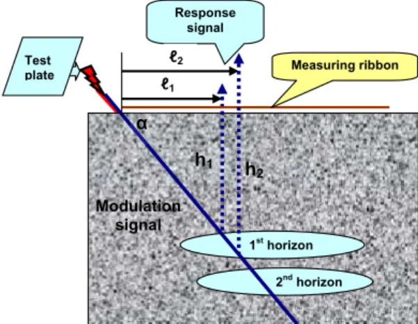
The magnetic field of the Earth is used as the source of a constant magnetic field to create NMR conditions in the molecules of a sought-for substance at depths of up to 5 km. The spectrum of resonance absorption signal of each of the sought-for minerals is pre-recorded on special test plates (Fig. 8):
The advantages of using such plates is that the absorption spectra of any minerals, including oil, consisting of hundreds of types of molecules may be transferred to them.
Test plates are further used for transmitter mod-ulation during survey of the corresponding mineral (patent UA no. 86168, 2013; patent UA no. 86169, 2013; patent UA no. 86497, 2013; PCT/UA2011/000033, 2011; PCT/UA2013/000036, 2013).
А
А
Surveyed area
Figure 9.Diagram of point-by-point deposit survey.
the signal modulated by test plate is directed towards the de-posit atαangle. Thanks to chemical shift the spectrum signal is weakly absorbed by various substances in the propagation path but undergoes significant absorption by oil molecules.
Operator moves along the measuring ribbon with receiver. Response signal is registered at distance fromℓ1toℓ2.
Occurrence depths of a horizon are calculated with the help of the following formulae:
h1=ℓ1·tgα
h2=ℓ2·tgα. (5)
Horizon thickness1his calculated the following way:
1h=h2−h1=(ℓ2−ℓ1)·tgα. (6)
The calculation is similar for the following horizons of de-posit.
Thus, in each measuring point we receive the following data:
– presence or absence of the sought-for material in the measuring point
– number of horizons in deposit
– approximate occurrence depths of horizons – approximate horizon thickness.
In some ways these data have something in common with those of exploratory drilling, but geophysical survey of de-posits is conducted faster and cheaper.
Test plates with records of resonance frequencies of natu-ral gas recorded at different pressure are placed consecutively
1st horizon
2nd horizon
Modulation signal
Figure 10.Diagram for measuring the parameters of deposit occur-rence.
in the transmitter modulator during survey of oil deposits. This enables us to further define
– presence of gas caps in the horizons
– thickness of gas caps
– pressure in gas caps.
In a number of cases, type of reservoirs and their cap rocks are identified by available samples (Kovalyov et al., 2010, 2011).
In total 40–50 point measuring points are required during work on location for deposit contouring and 20–30 measur-ing points for constructmeasur-ing sections.
The duration of measurements in each survey point is 30– 40 min.
7 Examples of executed works
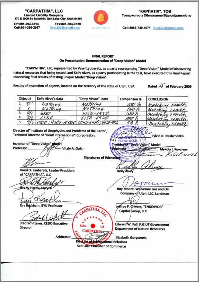
Testing and practical demonstration of innovative technology were conducted in 2009 on territory in Utah. The total area was 3600 km2. Directly on the terrain, five drilled wells were surveyed.
Control points (drilled wells) were scattered over the whole area and were provided one after the other as the sur-vey took place.
4 1753–1857/1794–1808 150–160/164
aGas flow rate of 0.26 m3day−1.
bThe drilling fluid disappeared from cavity.
Accidental discharges of “coal mine methane” occurred at the Zasyad’ko coal mine in Ukraine. In 2010 work was carried out on remote determination of methane origins under the mine shafts.
Drilling results in the point indicated by us confirmed the presence of the alleged source of natural gas. Table 1 shows comparison of results of our survey and data of sampling of drilled well.
The obvious results of work are an efficiency−100 % and an accuracy of depth detection of≥95 %.
8 Conclusion
The article considers theoretical possibilities and applied questions of NMR effect use with the aim of search and prospecting of hydrocarbon deposits.
It is shown that the main idea of the innovative method lies in “point-by-point sounding of an area with frequency spec-tra that excites resonance in the sought-for substance”. Using a highly directional antenna at the same time is compulsory.
Sequence of operations of ground sounding of hydrocar-bon deposits was developed as well as calculating procedure of occurrence depth of horizons and their thickness.
Works conducted on the basis of the considered method have shown high efficiency, accuracy and result repetition.
This initial work was aimed at creating a summary about the unique capabilities of an innovative NMR technology to carry out a direct detection of hydrocarbons, minerals and water deposits to a depth of 5 km without interpretation by highly directional antenna. The use of these features can sig-nificantly reduce an exploration budgets in exploration geo-physics.
9 Data availability
The authors of the paper state that all the data are publicly available.
responsible for the acquisition of field data and the technical design of the article.
Edited by: L. Vazquez
Reviewed by: F. Cortes and four anonymous referees
References
Bloch, F.: Nuclearinduction, Phys. Rev., 70, 460–474, 1946. Coates, G. R., Miller, M., Gillen, M., and Henderson, C.: The MRIL
in Conoco 33-1, An investigation of a new magnetic resonance imaging log: paper DD, 32nd Annual SPWLA Logging Sympo-sium Transactions, 24, 1991.
Coates, G. R., Xiao, L., and Prammer, M. G.: NMR logging. Princi-ples and application, Halliburton Energy Services, Houston, 356, 2001.
Derome, A. E.: Modern NMR Techniques for Chemistry Research, Pergamon Press, Oxford, 403 pp., 1992.
Hill, M. N.: Ship nuclear spin magnetometer, Intern. Hidrogr. Rev., 37, 309–311, 1960.
Kovalyov, N. I., Gokh, V. A., Ivashchenko, P. N., and Soldatova, S. V.: The experience of the practical use of complex equipment “Poisk” to determine the boundaries of oil&gas bearing areas and the choice of points for wells drilling, Geoinformatika, 4, 46–51, 2010.
Kovalyov, N. I., Soldatova, S. V, Gokh, V. A., and Ivashchenko, P. N.: Study on characteristics of occurrence of gas deposits in shale formations using complex remote equipment “Poisk”, Geoinfor-matika, 3, 27–29, 2011.
Markov, G. T. and Sazonov, D. M.: Electrodynamic bases of theo-ries of antennas: Energiya, Moscow, 528 pp., 1975.
Nalivayko, K. N. and Burcev, U. A.: Proton magnetometer PM-5, Geomagn. Aeronomy, 2, 343 pp., 1962.
Packard, M. and Varian, R.: Free nuclear induction the Earth’s mag-netic field, B. Am. Phys. Soc., 28, 7–12, 1953.
Packard, M. and Varian, R.: Free nuclear induction in the Earth’s magnetic field, Phys. Rev., 93, 941–945, 1954
Parcell, E., Torrey, H., and Pound, A.: Phys. Rev., 69, 37–38, 1946. Patent UA # 86168: A method of searching of natural gas deposits, available at: http://base.ukrpatent.org/searchINV/ search.php?action=viewdetails&IdClaim=194999/, last access: 17 November 2016.
Patent UA # 86169: A method of searching of natural gas deposits available at: http://base.ukrpatent.org/searchINV/ search.php?action=viewdetails&IdClaim=195000/, last access: 17 November 2016.
Pokonova, Y. V., Batueva, I. Y., Gaile, A. A., Spirkin, V. G., and Takhistov, V. V.: Oil Chemistry, Chemistry, Leningrad, 343 pp., 1984.
Pukhliy, V. and Kovalyov, N. I.: Nuclear magnetic resonance, The-ory and applications, Cherkassy state center for scientific, tech-nical and economic, 670 pp., 2010.
Salamatin, V. and Afonin, I.: Electrodynamics and radiowave propa-gation. Part 2, Radiowave propagation, Sevastopol, 72 pp., 2008.
PCT/UA2011/00003: The positive decision to the International ap-plication PCT/UA2011/000033, The system of remote explo-ration of mineral resources, available at: https://patentscope. wipo.int/search/en/detail.jsf?docId=WO2012154142/, last ac-cess: 17 November 2016.