DEVELOPMENT OF AN ACTIVE ORTHOSIS PROTOTYPE FOR LOWER
LIMBS
Márcio V. Araújo, [email protected] Pablo J. Alsina, [email protected]
Adelardo A. D. de Medeiros, [email protected] Jonathan P. P. Pereira, [email protected] Elber C. Domingos, [email protected] Fábio M. U. Araújo, [email protected] Jáder S. Silva, [email protected]
UFRN - Federal University of Rio Grande do Norte, DCA - Department of Computing Engineering and Automation, Natal, RN, Brazil
Abstract.This paper presents the development of a prototype of an active orthosis for lower limbs. The proposed orthosis is an orthopedical device with the main objective of providing walking capacity to people with partial or total loss of limbs movements. In order to design the kinematics, dynamics and the mechanical characteristics of the prototype, the biomechanics of the human body was analized. The orthosis was projected to reproduce the movements of human gait. The movements of the joints of the orthosis are controlled by DC motors equipped with mechanical reductions, whose purpose is to reduce rotational speed and increase the torque, thus generating smooth movements. An embedded electronic system for sensory data acquisition and motor control was projected. The gait movements of the orthosis will be controlled by high level commands from a human-machine interface based on processings of electroencephalogram signals, speech recognition or joystick.
Keywords:Active Orthosis; Exoskeleton; Biomechanics
1. INTRODUCTION
Since the time of the philosopher Hippocrates, the ancient Greeks had used rustic wooden devices to help or correct the movement injured limbs of the human body. The term orthosis (Houaiss & Villar 2001) refers historically to all non-invasive orthopedic mechanisms, externally positioned, whose function is to align, prevent or correct deformities or even improve the function of the moving parts of the body (Pratt 1994). In this context, an active orthosis will be used to help or even to produce the movements of the limbs of persons with some kind of paralysis, such as a spinal cord injury, or even a lack of strength due to muscle problems.
Recent advances on microelectronics, computing and new materials with high mechanical resistance and lightness allowed the development of robotic devices to assist the locomotion of people with difficulties or even impossibility of walking (Argo Medical Technologies 2008). Research on active orthosis and exoskeletons started in the 60s. Research groups working largely in parallel in the United States and Yugoslavia. The main focus of research for the Americans was the development of technologies for military purposes (Berkeley Robotics and Human Engineering Laboratory 2004), while for the Yugoslavian main intention was to develop equipment to assist people with special needs (Dollar & Herr 2007). For these two fields of research, there were many challenges, especially in portable equipments and interface with the human operator.
The increasing number of people with reduced mobility in the legs and paraplegic due to accidents and other factors has motivated the development of active orthosis. The census conducted in Brazil in 2000 reported that about one million people in the country have some type of paralysis in the limbs (paraplegia, quadriplegia or hemiplegia). The Brazilian network of Sarah Kubitscheck hospitals informs that 60% of cases of paralysis by spinal cord injury generate situations of paraplegia and 40% of quadriplegia. Considering also the cases of people with reduced mobility in the legs, there is a large contingent of potential users of devices to aid mobility. Currently, several research groups around the world are developing projects related to active orthosis for the lower limbs, with the goal of helping people with special needs (Mori, Okada & Takayama 2005, Kong & Jeon 2006).
In this context, this paper presents the first steps of the development of an intelligent active orthosis prototype for people with no movements in the lower limbs. The proposed orthosis will incorporate techniques of biped robot control in order to reproduce the human walking. The system will be commanded by high level commands, such as: walk, stop, turn left, turn right, down stairs, etc.
2. THE PROPOSED SYSTEM
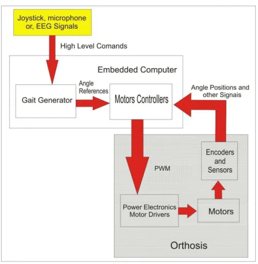
In this paper, an active orthosis for patients with no movements in their lower limb is proposed. In order to allow the walking of this kind of patients, the prototype will incorporate techniques used in biped robots for generation of stable gait. The orthosis will be commanded through high level commands, such as: walk, stop, turn left, turn right, down stairs, sit, etc. These high level commands could be generated from buttons or joystick, speech recognition or EEG (electroencephalogram) signal processing. The first version of the prototype will be commanded through a joystick. The architecture of the proposed system is shown in Fig. 1.
Figure 1. Architecture of the hardware
The electronic embedded system consists of an embedded computer (microcontroller or Digital Signal Processor), position encoders and other sensors (force, accelerometers, etc.), power electronics and motor drives. The embedded computer interprets the high level commands in order to generate an appropriate sequence of reference angular positions for the joints of the orthosis (gait generation). According to these joint position references and the information of the cur-rent state of the orthosis provided by the sensors, the embedded computer generates the PWM (Pulse Width Modulation) control signals to the power electronics, which will drive the motors of the orthosis.
The power electronics system consists of Full Bridge drivers used to deliver electric power to the DC motors of the orthosis. The motors are driven according to the PWM control signals generated by the embedded computer, which define the direction and amount of rotation of each motor. The PWM technique gives a more precise control over the torque and speed, allowing soft start of the DC motors (Braga 2005).
The current state of the orthosis is measured through position encoders and limit switches coupled to each joint motor. Each encoder generates a sequence of pulses whose frequency is proportional to the motor speed, providing accurate measures of the relative angular position of each joint, allowing precise control of the position of the orthosis. The limit switches prevent the joints of exceeding their mechanical limits of movement. An IMU (Inertial Measurement Unit) will be also included in order to guarantee a more precise control of the equilibrium of the system.
3. MODEL OF THE PROTOTYPE
As the proposed orthosis is a mechanism with pseudo-anthropomorphic characteristics, a previous study of the biome-chanics of the human gait was done before starting the project of the prototype.
Anthropometric data was analyzed, particularly the size of lower limbs, their masses, and the angles generated by the knee, ankle and hip joints during a standard walk.
As a reference for the design of the orthosis, it was assumed that the patient was a person weighing between 50 kg and 60 kg and height between 1.55 meters and 1.65 meters. This relationship between the weight and height specified in the project was based on a person with standard Body Mass Index (a patient with appropriate weight for his height). Table 1 shows the masses of the various parts of the body for this standard patient, as given in NASA (NASA 1995).
Table 2 shows, according to (Winter 1990), the average dimensions of the segments of the lower limbs of human body, which were used in the design of the orthosis, based a person of 1.55 meters high.
Table 1. Mass of human model
Parts of the body Mass (kg) Head 3.10 Neck 0.68 Chest 14.90 Abdomen 8.36 Upper limbs 4.73 Legs 12.22 Calves 4.85
Feet 1.22
Table 2. Dimensions of the lower limbs of human body
Body Segment Size (m) Thigh (Hip-knee) 0.360 Leg (Knee-ankle) 0.365
The prototype of the active orthosis for lower limbs is basically a mechanism consisting of a set of rigid structures joined by rotational joints (one degree of freedom each one), driven by DC motors. Figure 2 illustrates the design of the prototype developed using CAD tools.
Figure 2. Prototype of an active orthosis developed in CAD tools
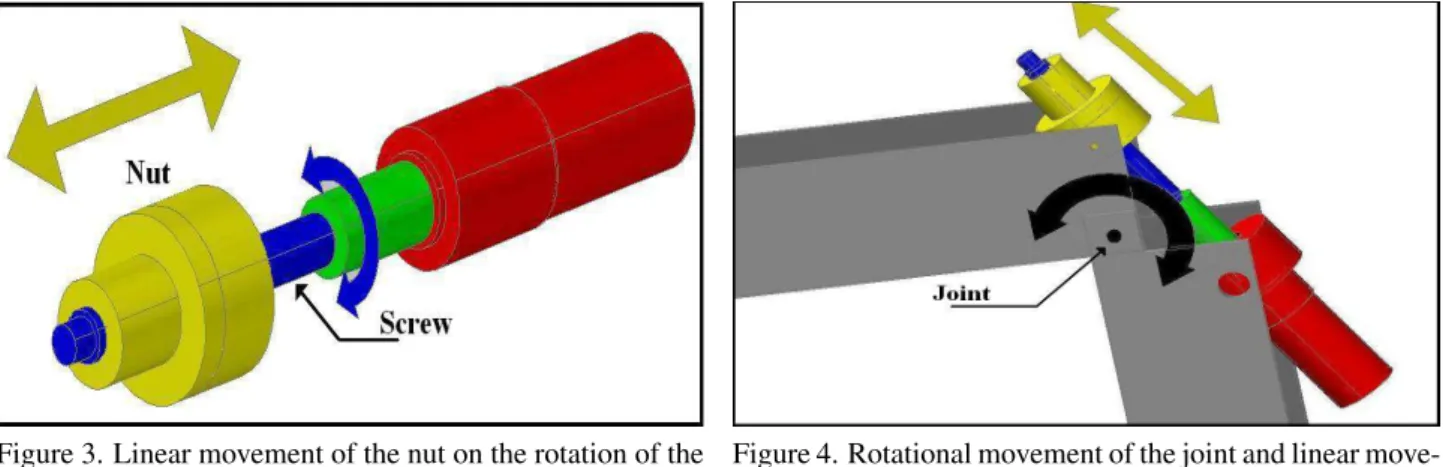
box and is coupled to a recirculating ball screw which drives the joint movement. As the motor is attached to the screw, its the rotation produces linear displacement of the nut of the ball screw along the direction of the motor axis. Figure 3 shows the conversion of rotational movement of the screw into the linear motion of the nut. In turn, the nut, attached to the corresponding joint of the orthosis, transmits its linear motion to it, causing its rotation in the sagittal plane. Figure 4 shows how the displacement of the nut along the ball screw produces a rotational movement in the joint .
Figure 3. Linear movement of the nut on the rotation of the ball screw
Figure 4. Rotational movement of the joint and linear move-ment of the nut
Obviously it would be easier to attach the motor directly on the axis of rotation of the joint, but, because the high torque required to perform this movement, low angular velocity, and angular positioning precision and reduced physical space, the mechanical arrangement described above was chosen. All calculations of torque and forces are discussed in the following section.
Most of the prototype was built in aluminum, including some plastic parts. The various parts of the structure were fixed to each other by means of screws. In the current stage of development, the prototype has a total weight of approximately 11.13 Kg, (not including yet the weight of the embedded systems and batteries).
Some dimensions of orthosis were obtained based on Tab. 2; however, to ensure comfort and a better fit to the height of the user, an adjustable length system was incorporated to the prototype structure. The orthosis is attached to the patient through elastic straps located at the legs and chest.
4. DIMENSIONING OF ACTUATORS
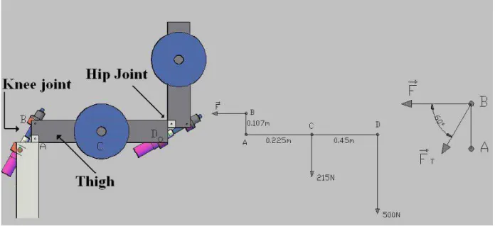
Based on tables 1 and 2 and according to the size of the prototype, a free body diagram of forces and torques was drawn for the worst case operational conditions. This case happens when the patient gets up from a seated position, with knee and hip joints at right angles of flexion and extension, respectively, as shown in Fig. 5. The objective here is to calculate the minimum motor torques which are necessary to get up. It is precisely this movement that requires more torques to drive the electric motors.
In the resolution of this problem all the forces actuating on the body are considered. Adopting a counter-clockwise convention and based on the balance equation, Eq. (1), which reflects the fact that the sum of the moments of the forces on point A is zero, the force F, shown in the free body diagram, can be calculated.
X
MA= 0 ⇒ F·0.107m−215N·0.225m−500N·0.45m= 0 ⇒ F =
274N m
0.107m = 2560.7N (1)
ForceFis related to the forceFT by Eq. (2):
FT =
F cos 60 =
2560.7N
0.5 = 5121.5N (2)
whereFT is the minimum linear force that the nut exerts to move the articulation. Based onFT, we can calculate the
torque needed to transform the rotary motion into linear motion, using Eq. (3):
MT a=
FT·P
2000·π·η
= 5121.5N·16mm
2000·π·0.9 = 14.5N m (3)
where theMT ais the motor torque required to move the joint,P is the step of the screw andη is the efficiency of the
Figure 5. Diagram of forces
5. PRELIMINARY RESULTS
Based on the design of torque, speed, power, voltage and electric current, a part of the orthosis was built: a leg, including the knee joint and the hip joint. This structure was useful to verify the performance of the prototype when lifting its load. Before doing tests with real patients, preliminar experiments using weights to simulate the human body were performed.. A DC external source was utilized to power the motors, as shown in Fig. 6.
Figure 6. Orthosis powered by an external source with loads
The tests had followed the same criterion of the static analysis used to calculate the values of the torques in the rotational joints. The friction losses between the moving parts were neglected in the calculations. In order to compensate these losses, a safety margin was added to the computed forces. In the experiments, the prototype was able to lift its maximum load, confirming the previous calculations.
The tests will be useful to point out some flaws in the construction of the prototype, such as excessive clearances, rupture of parts under certain load conditions, excess weight in the structure, among others. Another important factor considered was the total amount of electrical current required by the motors. This factor is related to the consumption of energy and the autonomy of the prototype.
6. CONCLUSION
of this work was achieved: the development of a functional mechanical design of the orthosis and its construction. This allowed to observe several key points. One of them was the need of reduction of the total weight of the mechanical struc-ture, considering that the final weight is reasonably high. However, there are some parts of the orthosis that whose weight cannot be reduced, such as the motors. The found solution was to replace the metallic materials of some noncritical parts of the structure by polymers that offer the same strength and also reduced weight. According to the results presented in this paper, the next step is the construction of the complete orthosis and integration of the embedded electronics. Cur-rently, experiments on recognition of EEG signals that will be used to command the orthosis are under research. Future works include the implementation of a stable gait generator for the prototype.
7. ACKNOWLEDGEMENTS
This work is supported by CNPQ (Conselho Nacional de Desenvolvimento Científico e Tecnológico)
8. REFERENCES
Argo Medical Technologies (2008). Rewalk, http://www.argomedtec.com/.
Berkeley Robotics and Human Engineering Laboratory (2004). Bleex - the berkeley lower extremity exoskeleton project, http://bleex.me.berkeley.edu/bleex.htm.
Braga, N. C. (2005). Eletrônica Básica Para Mecatrônica, Editora Saber ltda., São Paulo.
Dollar, A. M. & Herr, H. (2007). Active orthoses for the lower-limbs: Challenges and state of the art,Proceedings of IEEE International Conference on Rehabilitation Robotics, Noordwijk, Netherlands.
Houaiss, A. & Villar, M. S. (2001). Dicionário Houaiss da língua portuguesa, Objetiva, Rio de Janeiro.
Kong, K. & Jeon, D. (2006). Design and control of an exoskeleton for the elderly and patients,IEEE/ASME Transactions on Mechatronics.
Mori, Y., Okada, J. & Takayama, K. (2005). Development of straight style transfer equipament for lower limbs disabled,
Proceedings of IEEE/ASME International Conference on Advanced Intelligent Mechatronics, pp. 1176–1181. NASA (1995). Man-systems integration standards, v.i,s.3 – anthopometry and biomechanics,Technical report, NASA.
http://msis.jsc.nasa.gov/sections/section03.htm.
Pratt, D. J. (1994). Some aspects of modern orthotics,Physiological Measurement15: 1–27.