International Journal for Quality Research 10(3) 641–660 ISSN 1800-6450
641
Mohammed Yunus
1Mohammad S. Alsoufi
Mohammed Irfan
Article info: Received 12.02.2016 Accepted 19.07.2016 UDC – 332.05 DOI – 10.18421/IJQR10.03-14
APPLICATION OF QC TOOLS FOR
CONTINUOUS IMPROVEMENT IN AN
EXPENSIVE SEAT HARDFACING PROCESS
USING TIG WELDING
Abstract: The present study is carried out to improve quality level by identifying the prime reasons of the quality related problems in the seat hardfacing process involving the deposition of cobalt based super alloy in I.C. Engine valves using TIG welding process. During the Process, defects like stellite deposition overflow, head melt, non-uniform stellite merging, etc., are observed and combining all these defects, the rejection level was in top position in Forge shop. We use widely referred QC tools of the manufacturing field to monitor the complete operation and continuous progressive process improvement to ensure ability and efficiency of quality management system of any firm. The work aims to identify the various causes for the rejection by the detailed study of the operation, equipment, materials and the various process parameters that are very important to get defects-free products. Also, to evolve suitable countermeasures for reducing the rejection percentage using seven QC tools. To further understand and validate the obtained results, we need to address other studies related to motivations, advantages, and disadvantages of applying quality control tools.
Keywords: Q Quality Control Tools, Continuous
Improvement, Seat Hardfacing, TIG Welding, ICE valves, PDCA, Efficiency
1.
Introduction
1The seat hardfacing (Deposition) process is used to deposit cobalt-based super alloy possessing higher wear, corrosion and heat resistance properties in I.C. engine valves, which is carried out at Kar Mobiles Limited, India. The company is manufacturing Inlet and exhaust valves for I.C. Engines such as marine, locomotive, battle tanks, farm
1 Corresponding author: Mohammed Yunus
email: yunus.mohammed@rediffmail.com
current, stellite rod feed and shielding gas flow rate during the TIG welding process are very important process parameters in terms of obtaining defect-free products. Therefore, identifying the various causes for the rejection and evolving suitable countermeasures to reduce the rejection level was a priority.
Information about the firms, processes involved like TIG welding, origin of defects as well as their level of priority and the use of basic and advanced Quality Tools were collected and after conducting various hypotheses tests, results were analyzed and discussed to standardize them.
In this article, we have presented a detailed aspect of application of quality tools with number of tables to bring awareness on the use of quality tools for various production companies irrespective of their size, type and strength. It also identifies the potential of each quality tool in continuous improvement and productivity. Finally, few suggestions are also included for future work to improve and extend this research.
2.
Literature review
Every manufacturing organization is aiming to achieve the quality of their products as quality and productivity are considered for bringing prosperity into the organization as well as to the nation and improve the quality of work life. Quality is a relative term and refers to the end use of the product. The requirements of the end user will define a product's quality and quality is a continuous improvement process achievable in a planned and controlled way (Juran et al., 1998). The seven QC tools are the simple statistical tools used for problem-solving developed by Japan. Kaoru Ishikawa suggested the role of these QC tools in solving almost 95 percent of all problems. An organization must be both effective and efficient to improve the quality of a product and such improvement is accomplished by recognizing the root of the problems and
fixing them in an appropriate way (Rissik, 2013). In order to solve quality problems, the seven QC tools used are as follows:
1) Pareto Diagrams
2) Cause and Effect Diagrams 3) Histograms
4) Control Charts 5) Scatter Diagrams 6) Graphs and 7) Check Sheets.
643 Table 1. Types of graphs and their purposes
in quality control Graph
Types
Purpose
Bar Graph
To compare sizes of data
Line Graph
To represent changes of data
Gantt Chart
To plan and schedule
Radar Chart
To represent changes in data
Band Graph
To represent changes in data
Pie Chart To indicate comparative weights
ISO Graph
To represent data using symbols
2.1. Development of hardfacing process
The first development of Hardfacing using welding is found in a patent by J. W. Spencer in 1896, but like many other processes, it was not developed industrially for a considerable time. In 1919, a British patent was granted to S. Z. de Ferranti for the protection of steam valves with cobalt-nickel alloys and by 1922 hardfacing alloys had been adopted extensively in oil well drilling for the facing of the cutting edges of rotary drills. This job was so successful that it brought about considerable demand for the hardfacing rod that is in fact the beginning of the art. As there were no oil wells in Great Britain, this major development in Hardfacing was carried out in the United States.
On the introduction of the cemented carbides in the 1920's inserts and small particles were welded into position by melting a steel welding rod around them, and again the oil-well drills were greatly increased and at one locality, for instance, in 1927 it required eighty-four forged and tempered steel fishtail bits to complete a well. The use of cobalt-based hardfacing alloys reduced this number to forty-four, and with carbides, only fourteen drills were used (Riddihough,
1975).
2.2. Hardfacing of internal combustion engine valves
The hardfacing technique in case of I.C. engine valves was developed in the early1920 (Singaiah and Charyulu, 2012). With the development of high compression ratios, valve head temperature increased, and as no suitable steel was available, hardfacing was used to protect the valve seating of an IC Engine valve (Singaiah and Charyulu, 2012). Present day, diesel and high duty petrol engine valves usually consist of an austenitic stainless steel body, nitride hardened on the stem to resist wear. The tip of the stem is hardfaced to resist tappet wear and the seating and often the entire head is hardfaced to resist corrosion and wear. Prior to the advent of the gas turbine virtually every poppet valve used in aero engines was hardfaced. Another extensive development in hardfacing, which was introduced in 1933, is its use for building-up worn railway crossings. A low alloy steel rod gives a tough deposit with high resistance to frictional wear and the process is now used extensively on the railways. Since 1930, hardfacing has been extended into most industries and the process is useful in reclaiming worn components. Its major use, however, is to enable new components to be manufactured with a minimum valuable alloy to give maximum service life and output (Ayano, ).
et al., 1993).
The Cobalt-based Stellite alloys are the most well-known and successful alloys, with best properties like excellent mechanical wear resistance, especially at high temperature, with very high corrosion resistance (Riddihough, 1975). Cobalt-chromium-molybdenum (Tribaloy) alloys were developed for resisting extreme wear combined with high temperature and corrosion. They are very suitable for using in adhesive wear conditions due to the high content of molybdenum possess excellent dry-running characteristics. Similarly, Nickel-chromium-molybdenum (Nistelle) alloys are developed to resist corrosion, especially in hostile chemical domain due to rich content chromium and molybdenum which provides superior pitting resistance rather than wear. Carbon particles in nickel or cobalt (Stelcar) alloys present in powder form can be applied by thermal spraying or weld hardfacing techniques. Iron based (Delcrome) alloys are developed to provide resistance to abrasive wear at very lower temperatures (up to 200°C) but their corrosion resistance is low compared to Tribaloy or Nistelle alloys (see. Hardfacing alloys and welding methods).
Figure 1 illustrates the Products of Kar Mobiles Limited Company. Table 2 and 3 provides the details of manufacturing
capability and configuration of engine valves of the company.
2.3. Gas tungsten arc welding
In the case of the Gas Tungsten Arc Welding (GTAW) or HeliArc, two welding methods were developed namely, tungsten inert gas (TIG) and tungsten arc welding (TAW) during the beginning of 1940 when the need arose to weld magnesium which was impossible. Russell Meredith introduced and produced welding process using the inert gas helium and a tungsten electrode to fuse magnesium. This joining method replaced the riveting process of building aircraft with the aluminum and the magnesium components.
Figure 1. Photograph of products of car mobiles Ltd
Figure 2. Schematic drawing of components and parameters and the automatic feeding of filler material for the TIG welding.
645 changes, but without much changes in the
fundamentals demonstrated by Meredith as shown in figure 2.
In the GTAW, the melting temperature required to weld materials is by an arc between a tungsten alloy electrode and the workpiece can approach 2500°C in the presence of an inert gas [argon, helium, or a mixture of helium and argon] which protects from atmospheric contamination (Bohnart and Staff, 2005).
Table 2. Manufacturing capability of engine valves
Table 3. Configuration of valves in Kar mobiles Ltd
Mono Metal
Upsetting and Forging Bimetal Friction Welding and Projection
Welding
Head Finish Machine Finish and Forge Finish Seat Hardfaced Induction Hardened Tip End Flame Hardened, Induction Hardened
and Stellite Faced
Advantages of Gas Tungsten Arc Welding are providing a concentrated heating of the work piece resulting in a narrow heat- affected zone, an effective protection of the weld pool by an inert shielding gas, independent of filler material, after treatment of the weld as no slag or spatter is produced and good for welding thin with similar or dissimilar material. Disadvantages of Gas Tungsten Arc Welding are slower deposition rate, necessity for a skilled hand-eye coordinated operator and the fact that the equipment costs more. Application of Gas Tungsten Arc Welding: welding of stainless steels, aluminium, nickel, nickel alloys,
petrochemical, food, chemical, nuclear, offshore industry and power plants (see. Tungsten guidebook, 2002). Types of Tungsten electrode for TIG welding are pure tungsten electrode, Cerium tungsten electrode, Lanthanum tungsten electrode, Thorium tungsten electrode and Zirconium tungsten electrode (Bohmart and Staff, 2005; Technical specification for TIG welding; Tungsten Guidebook, 2002).
3.
Research methodology
The following methodology or technique was used to identify the defects and evolve suitable counter measures to reduce the rejection in the Seat Hardfacing process in an I.C. Engine Valve.
Problem selection: To clarify what the problem is that you are to solve.
Observation: To clarify the reason for the selection of the problem by positioning the problem using Pareto Diagram and other tools.
Analysis: This is the central activity in the problem solving procedure with the QC approach and it refers to an activity to quantitatively link the characteristics in question to the true causes and /or effective counter measures. Here, possible causes are identified by all the people concerned using a Cause-and- Effect Diagram, and then those causes which are considered to be root caused are verified using various statistical techniques including design of experiments.
Action: To take action on the root causes which are identified through analysis.
Check: This step is also a characteristic feature of the problem solving procedure with the QC approach and it means that the result of the actions taken must be confirmed and then the PDCA cycle must be rotated without fail.
Standardization: Once the effect is confirmed, “standardization” should be Specification Min.
(mm) Max.
(mm) Raw Material Used Head
Diameter 18 105
Low Carbon Steel. Martensitic Valve Steel. Austenitic Valve Steel. Nickel Alloy. Stainless Steel. Stem
Diameter 5 22 Overall
instituted in order to organizationally prevent occurrence of the problem.
Conclusion: This step means what is yet to be resolved is made clear and the activity is to be reviewed to see if the process has been appropriate as a problem solving procedure and to find possible improvement for its future implementation i.e. the control cycle is to be rotated over the way the problem is solved (Ayano, -; Katsuya, 2001).
3.1. Problem selection
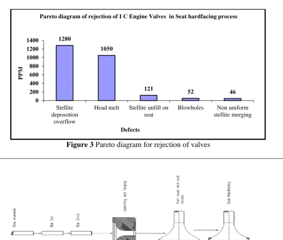
The rejection data was collected during the period of April to July for data analysis. During this period a total 2549 PPM were rejected and this constituted a rejection level to top level in Seat hardfacing process in an I. C. Engine Valves. From the data obtained, a Pareto diagram was drawn (refer figure 3) to identify the defects in this process. It was found that the defects in the Seat hardfacing process of an I C Engine Valve contribute to 2549 PPM of the rejection, which was the highest in the Forge shop.
Stellite deposition overflow, Head melt, Stellite unfilled on seat, Blowholes and Non uniform stellite merging respectively are the defects shown in figure 5.
3.2. Observation
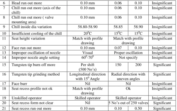
By observing the component process flow diagram for the purposes of identifying the operation contributing to the rejection of I.C. Engine Valves in the Seat hardfacing process as shown in Figure 4.
3.2.1. GEMBA Study for clarity of data in seat hardfacing process
By observing the GEMBA (Work spot), Seat hardfacing is the process used to weld and fill the stellite rod to the seat recess portion
by the TIG welding machine as shown in the figure 6. Before the Seat deposition process a seat recess operation is carried out on the Valve head for depositing the Stellite rod by TIG welding machine. During the seat recess operation, recess depth of 1.2 mm towards the radius is removed and matched with the profile drawing, which is used for checking the seat recess profile. During the seat deposition by TIG, many defects like Stellite deposition overflow, Head melt, Stellite unfill on seat, Non uniform stellite merging and Blowholes are identified.
3.3. Analysis
Based on the GEMBA study, brainstorming to identify all the possible causes for the I.C. Engine Valves defects is undertaken and its results are listed below.
Chill rotation speed variation, Current variation, Stellite rod feed variation, Head diameter variation, Head not clear, Tungsten electrode tip burn off more, Chill run out more (axis of the chill), Chill run out more (valve mounting area), Chill inside diameter variation, Seat recess form not clear, Seat recess run out more, Insufficient cooling of the chill, Seat height variation, Face run out more, Improper oscillation of the nozzle, Improper nozzle angle setting, Head run out, Face burr, Unskilled operator and Seat recess profile not ok, etc.
After identifying the possible causes through brainstorming, a Cause and Effect diagram (refer to figure 7) is used to show the systematic relationship between a result and its possible causes. The causes were categorized under the following headings:
Material
Man
647
Figure 3 Pareto diagram for rejection of valvesFigure 4. Schematic view of process flow diagram for valves
Figure 5. Photograph of I.C. Engine Valves defects
1280
1050
121 52
46 0
200 400 600 800 1000 1200 1400
Stellite deposotion
overflow
Head melt Stellite unfill on seat
Blowholes Non uniform
stellite merging
PPM
Defects
Figure 6. TIG welding machine and partial schematic drawing of seat hardfacing process
Figure 7. Cause and Effect diagram for the rejection of I C Engine Valves
3.3.1. Experimental data sheet for possible causes
Table 4 and 5 give the experimental data for the primary possible and secondary possible causes (Significant causes) for the rejection of I C Engine Valves. From these tables, it is found that some of the causes become
significant and some of the causes are insignificant.
3.3.2. Root causes for significant causes by Why-Why analysis
By close study of the actual workplace and the generating of a counter measure plan which is readily accepted by the workplace.
Table 4 Data collection table for the possible causes
No. Possible causes Specification Observation Significant/
Insignificant
Min Max
1 Chill Rotation Speed Variation 27-29 Sec 20 40 Significant
2 Current Variation 270-290 Amp 220 300 Significant
3 Stellite rod feed variation 180-185 mm 150 220 Significant 4 Head dia variation 58.80-58.90 58.60 58.90 Significant
5 Head not clear Nil No Head not clear
found
649
6 Head run out more 0.10 mm 0.06 0.10 Insignificant
7 Chill run out more (axis of the chill)
0.10 mm 0.06 0.10 Insignificant 8 Chill run out more ( valve
mounting area)
0.10 mm 0.06 0.10 Insignificant 9 Chill inside dia variation 58.80-58.90 58.85 58.90 Insignificant 10 Insufficient cooling of the chill 200C 150C 150C Insignificant 11 Seat height variation Match with profile
drawing
Match with profile drawing
Insignificant
12 Face run out more 0.10 mm 0.07 0.10 Insignificant
13 Improper oscillation of nozzle Visual Proper oscillation Insignificant 14 Improper nozzle angle setting 600-700 Not specify Insignificant 15 Tungsten tip burn off more Per shift
(500 No’s) 150 200 Significant
16 Tungsten tip grinding method Longitudinal direction with 150Angle
Radial direction with uneven angles
Significant
17 Face burr Nil Nil Insignificant
18 Seat recess profile not ok Match with profile drawing
Ok Insignificant 19 Unskilled operator Skilled operator Skilled operator Insignificant 20 Seat recess form not clear Nil 5 No’s out of 250 valves Significant 21 Seat recess run out more 0.10 mm 0.10 0.50 Significant Table 5 Data collection table for the significant causes
No. Possible causes Specification Observation Significant/
Insignificant
Min Max
1 Chill Rotation Speed Variation 27-29 Sec 20 40 Significant
2 Current Variation 270-290 Amp 220 300 Significant
3 Stellite rod feed variation 180-185 mm 150 220 Significant 4 Head dia variation 58.80-58.90 58.60 58.90 Significant 5 Tungsten electrode burn off
more
Per shift (500 No’s) 150 200 Significant
6 Wrong tungsten electrode grinding method
Longitudinal direction with 150 angle
Radial direction with uneven angle
Significant 7 Seat recess form not clear Nil 5 No’s out of 250
valves
Significant 8 Seat recess run out more 0.10 mm 0.10 0.50 Significant Table 6. Root causes for the major causes by why-why analysis
Causes Chill rotation speed variation [f15(1)] Current variation [f15(4)]
Why Voltage varying from 60-80 volts Trigger signal not coming from main control card
Why Supply coming from carbon brush is
varying Thyristor shorted & damaged the PCB card Why Due to worn-out of carbon bush
Root causes Carbon bush worn-out Over load Counter
measure Brush less DC motor is replaced Control fuse provided
Causes Stellite rod feed variation[f15(3)] Head dia variation
varying
Why Due to worn-out of carbon bush Conventional machine Root causes Change of carbon bush Less consistency Counter
measure AC motor with AC drive is provided Operation is carried out by CNC machine Causes Tungsten electrode burn off more Wrong tungsten electrode grinding
method
Why Tungsten electrode tip specification is not
maintained Tungsten electrode tip preparation is done manually
Why Tungsten electrode tip preparation is done manually
Why Specific tungsten electrode tip preparation machine is not available
Specific tungsten electrode tip preparation machine is not available
Root causes Tungsten electrode tip preparation should be done by specific machine only
Tungsten electrode tip preparation should be done by specific machine only
Counter measure
Procurement of Tungsten electrode grinding machine
Procurement of Tungsten electrode grinding machine
Causes Seat recess form not clear Seat recess run out more
Why Sliding movement of the tool is not proper Sliding movement of the tool is not proper Why Hydraulic pressure variation Hydraulic pressure variation
Why Conventional machine Conventional machine
Root causes Operation should be done by CNC m/c
only Operation should be done by CNC m/c only
Counter
measure Operation is carried out by CNC machine Operation is carried out by CNC machine
3.4. Action
The following recommendations are for process parameters and setting methods to get the best results. A few trials were conducted to ensure consistency in the result, they were found to meet the quality requirements with advisable methods listed and discussed below.
3.4.1. Tungsten electrode grinding method
The tungsten electrode tip shape is an important process parameter in precision TIG welding process. Accurate tungsten electrode tip shape geometry demands to fulfil various attributes like longer life, difficult starting of arc, shallower weld penetration and narrower arc shape during the process.
Actual Method
Tungsten electrode tip grinding is done in the common grinding machine and also it is prepared by a manual method with radial grind marks (refer figure 8) and this leads to restriction of the welding current, causes arc wandering, difficult starting of an arc, less stability in the arc and contaminations lower weld quality and also decreasing the tungsten electrode life.
Advisable
Method
651
Figure 8. Wrong way tungsten preparationFigure 9. Ideal way of tungsten preparation
The most important element for proper taper grinding is that the electrode must be ground longitudinally (lengthwise) with a taper grind distance of 2-2.5 times the electrode diameter, tip flat of 0.25-0.5 times the electrode diameter and with an included angle of 150-300. For the best possible arc stability, the tungsten electrode should be done with the length of the electrode at a 900 angle to the axis of the grinding wheel with a tip flat and as a surface finish of a prepared taper surface should be within 20-40 RMS as shown in figure 9.
3.4.2. Tungsten electrode type
temperature at the tip based on the work capacity of the element.
Figure 10. 2% Thoriated tungsten and 1.5% Lanthanum tungsten electrodes and proposed tip preparation
ActualMethod
Tungsten electrode with 2% Thoriated oxide contains thorium and has very low level radioactive material, thus vapors, grinding dust and disposal of thorium raises health and safety and environmental concerns. These electrodes are usually preferred for DC applications, the electrode is ground to a point and due to this the life of the tungsten electrode tip is shortened considerably and this leads to arc wandering and more difficulty in arc starting shown in figure 10.
AdvisableMethod
Tungsten electrode with 1.5% Lanthanum oxide is non-radioactive, these electrodes have excellent arc starting, low burn-off rate, arc stability and excellent re-ignition characteristics. 1-2% Lanthanum electrodes increase the current carrying capacity by approximately 50% for a given size electrode compared to pure tungsten and this leads to having longer life and providing greater resistance to tungsten contamination of the weld.
3.4.3. Gas nozzle with gas lens
The gas nozzle with gas lens is constructed in such a way that the shielding gas passes through a wire grid in order to make the flow of shielding gas more stable at a longer distance, because of this the electrode can have a longer stick-out thus allowing the welder to have a better view of the weld pool. Because of these characteristics the
consumption of shielding gas can be reduced to 20-30% of common gas nozzle.
ActualMethod
A common gas nozzle is used in the TIG torch, the shielding gas exit with a turbulent stream of flow and this begins to spread out at the tip of the gas nozzle, because of this the flow of shielding gas will not reach the welding zone and this leads to getting atmospheric air entry in the welding zone and causes welding defects. To overcome this problem it is necessary to use more shielding gas shown in figure11.
Advisablemethod
A gas nozzle with gas lens makes the flow of shielding gas (refer figure 11) with a column stream of gas and this allows the electrode to stick out for a longer time enabling the welder to have better visibility. The gas lens has a wire grid in order to make the flow of gas more stable at a longer distance so that the gas consumption can be reduced to a moderate level and this can -avoid the entry of atmospheric air into the welding zone and thereby we can achieve defect free welding.
3.4.4. Stellite rod feed and TIG torch angle
653 melting and achieve defect-free welding
these are the best suited parameters for TIG welding.
Actualmethod
The stellite rod feed and TIG torch angles
are set manually with approximate method. Due to this the TIG arc does not perfectly melt the stellite rod and the base material and for this reason welding will not satisfy the quality requirements.
Figure 11. Common gas nozzle, TIG torch with common gas nozzle and gas nozzle with gas lens
Advisablemethod
The stellite rod feed and TIG torch angles should be set with the help angle plate for accurate measurement. The Stellite rod feed should be set within the range of 150-300 and the TIG torch angle set within the range of 600-750 as shown in figure 12.
3.4.5. Shielding gas flow meter
In order to adjust the required gas flow for the TIG welding it is necessary to provide a Gas flow meter.
Actual Method
The gas flow is set with approximate method, because of this sometimes the gas flow rate may be less or more and this leads to causing more likelihood of getting defects in the welding and also more shielding gas consumption during the welding process.
AdvisableMethod
In precision TIG welding the shielding gas constitutes a very important process parameter to get a defect-free welding. The gas flow rate should be 07-12 ltr/min for a
common gas nozzle and 05-6.5 ltr/min for a gas lens nozzle. These can be accurately set by digital flow switch and from this it is possible to obtain the exact required flow rate during the TIG welding process.
The proposed counter measure and advisable methods need to be tried out in the actual production site and the person responsible for implementing the counter measure should have been decided by coordinating the matter with all the related departments. A decision is taken as to when the proposed counter measure will be tried out through 3W-1H format as shown in Table 7.
3.5. Check
Confirmation of effect is the most characteristic feature of the problem solving procedure in the QC story. Once the counter measure is fully implemented it is necessary to confirm its effects by the experimental data.
3.5.1. Experimental data
variation, Stellite rod feed variation, Head diameter variation, Tungsten electrode tip burn off more, Wrong tungsten electrode tip grinding method, Seat recess form not clear and Seat recess run out more, the experimental data is collected and the result observed is as shown in tables 8-15.
3.5.2. Before and after defects pareto diagram
To see the result from the recommended counter measure and advisable methods to the rejection of seat hardfacing process for an ICE valve is done by using a Pareto diagram and is as shown in figure 13.
Table 7. 3W-1H format for implementing the counter measure
No. What When Who How
1 Chill rotation speed variation
15-11-14 Author
1 Providing bush less DC motor instead of worn-out Carbon bush DC motor.
2 Current variation
12-01-15 Author
1 Providing control fuse for avoiding overload to the machine.
3 Rod feed variation
05-02-15 Author
1 Replacing Dc motor to the AC motor with AC drive for more accuracy.
4
Head dia variation, Seat recess form not clear, Seat recess run out more
06-12-14 Author 2
Carry out the operation in CNC machine.
5 Tungsten electrode type
15-04-15 Author
3 By purchasing 1.5% Lanthanum instead of 2% Thoriated.
6 Gas nozzle with gas lens
15-07-15 Author
2 By replacing Import torch to Local torch with gas lens in the TIG torch.
7 Flow meter
04-08-15 Author
2 By procuring flow meter and fixing in the machine
8 Stellite rod feed angle and TIG torch angle
04-08-15 Author
2 By providing angle plate in the machine for stellite rod feed and TIG torch angle.
9
Tungsten electrode burn off more, Wrong tungsten electrode grinding method
04-08-15 Author 3
By procuring tungsten electrode grinding machine and giving procedure for tip preparation.
Table 8. Experimental data for chill rotation speed variation
No. Specification in secs Observation in secs No. Specification in secs Observation in secs
1
Part No-1152367 16-18
16 26
Part No-1152367 16-18
16
2 16 27 16
3 16 28 16
4 16 29 16
5 16 30 16
6 16 31 16
7 16 32 16
8 16 33 16
9 16 34 16
10 16 35 16
11 16 36 16
12 16 37 16
13 16 38 16
14 16 39 16
15 16 40 16
16 16 41 16
17 16 42 16
655
19 16 44 16
20 16 45 16
21 16 46 16
22 16 47 16
23 16 48 16
24 16 49 16
25 16 50 16
Table 9. Experimental data for current variation
No. Specification in amps
Observation in amps No. Specification in amps
Observation in amps
1
Part No-1152367 230-250
240 26
Part No-1152367 230-250
240
2 240 27 240
3 240 28 240
4 240 29 240
5 240 30 240
6 240 31 240
7 240 32 240
8 240 33 240
9 240 34 240
10 240 35 240
11 240 36 240
12 240 37 240
13 240 38 240
14 240 39 240
15 240 40 240
16 240 41 240
17 240 42 240
18 240 43 240
19 240 44 240
20 240 45 240
21 240 46 240
22 240 47 240
23 240 48 240
24 240 49 240
25 240 50 240
Table 10. Experimental data for stellite rod feed variation
No. Specification in mm Observation in mm No. Specification in mm Observation in mm
1
Part No-1152367 75-80
80 26
Part No-1152367 75-80
80
2 80 27 80
3 80 28 80
4 80 29 80
5 80 30 80
6 80 31 80
7 80 32 80
8 80 33 80
9 80 34 80
10 80 35 80
11 80 36 80
12 80 37 80
14 80 39 80
15 80 40 80
16 80 41 80
17 80 42 80
18 80 43 80
19 80 44 80
20 80 45 80
21 80 46 80
22 80 47 80
23 80 48 80
24 80 49 80
25 80 50 80
Table 11. Experimental data for head dia. variation
No. Specification in mm Observation in mm No. Specification in mm Observation in mm
1
Part No-1152367 42.81+/-0.05
42.80 26
Part No-1152367 42.81+/-0.05
42.82
2 42.80 27 42.82
3 42.80 28 42.82
4 42.80 29 42.82
5 42.80 30 42.82
6 42.80 31 42.82
7 42.80 32 42.82
8 42.80 33 42.82
9 42.80 34 42.82
10 42.80 35 42.82
11 42.80 36 42.82
12 42.80 37 42.82
13 42.80 38 42.82
14 42.80 39 42.82
15 42.80 40 42.82
16 42.80 41 42.82
17 42.82 42 42.82
18 42.82 43 42.82
19 42.82 44 42.82
20 42.82 45 42.82
21 42.82 46 42.82
22 42.82 47 42.82
23 42.82 48 42.82
24 42.82 49 42.82
25 42.82 50 42.82
Table 12. Experimental data for Tungsten electrode tip burn off more
No. Specification Observation
01 The tungsten tip burn off should be Per shift
(500 no’s) Tungsten electrode tip burn off is 380-400 (Manual grinding) no’s
Table 13. Experimental data for wrong tungsten electrode grinding method
No. Specification Observation
01 Longitudinal with an angle of 150 Longitudinal direction with an angle of 14 0
657 Figure 12. Stellite rod feed and TIG torch angles
Table 14. Experimental data for Seat recess form not clear
No. Specification Observation
1 Nil Nil
Table 15. Experimental data for seat recess run out more
No. Specification in mm Observation in mm No. Specification in mm Observation in mm
1
Part No- 1152367 Run out 0.10
0.06 26
Part No-1152367 Run out 0.10
0.03
2 0.05 27 0.07
3 0.07 28 0.08
4 0.03 29 0.09
5 0.07 30 0.06
6 0.08 31 0.06
7 0.09 32 0.07
8 0.06 33 0.07
9 0.06 34 0.03
10 0.05 35 0.07
11 0.07 36 0.08
12 0.03 37 0.09
13 0.07 38 0.06
14 0.08 39 0.06
15 0.09 40 0.05
16 0.06 41 0.07
17 0.06 42 0.03
18 0.07 43 0.06
19 0.03 44 0.06
20 0.07 45 0.05
21 0.08 46 0.07
22 0.09 47 0.03
23 0.06 48 0.07
24 0.06 49 0.08
Figure13. Before and after rejection Pareto diagram
4.
Results and discussion
A few trials were conducted after the counter measure and advisable method, they were found to meet the quality requirements as follows:
The chill rotation speed in f15 (1) found to be constant during the process and also the TIG welding satisfies the quality requirements. Current in f15 (2) found to be constant during the process and also it is observed that TIG welding satisfies all the quality requirements. It is observed that, after the counter measure implementation in f15 (3), the stellite rod feed found uniform.
The turn head, seat recess operations are carried out in a CNC machine and it is observed that no head dia variation, seat recess form Ok and also seat recess run out lies within the specification.
By using 1.5% Lanthanum tungsten electrode in the TIG welding process, the tip life of the tungsten electrode becomes more i.e., 380-400 no’s as compare 150-200 no’s
in 2% Thoriated tungsten electrode. And also it is observed that tungsten electrode found less contamination after the welding process.
Suggestion is given to use gas lens in the TIG torch for the f15 (1), f15 (2), f15 (3) machines for better shielding gas flow to the welding zone during the TIG welding process. By using gas lens, shielding gas consumption is saved up to 50 Ltr / machine. Suggestion is also given to use flow meter in the f15 (1), f15 (2), f15 (3) machines for better control of shielding gas flow rate during the TIG welding process. Suggestion is made to provide an angle plate for stellite rod feed and TIG torch in all the TIG welding machines for better results in the TIG welding process.
659 better results in the TIG welding
process.
4.1. Standardization
Standardize the new counter measure and advisable methods to reduce the rejection of an ICE valves in seat hardfacing process by updating standard operating procedure, maintenance optimal check sheet and creating new part no for procurements of suggested item (Eker, 2010).
5.
Conclusions
In this research work, role and systematic approach of 7 QC tools in producing defects free products from product development to managing processes have been presented in the production process. It is very important for any organization to produce high quality products and maintain that quality to promote customer satisfaction and maintain standards. This is achieved by the efficient use of men, material, machine and management. This means that the quality of a product is mainly dependent on the skill of the operator, efficiency of the machine and quality of the material used. This work on reduction of rejection in seat hardfacing process of an I.C. Engine valve was successfully completed by using seven quality control tools. As it is presented in selected defects, quality tools played an important role in the collection of data, analysis, visualization, standardization and making sound base for data founded decision making. Moreover, the suggestions as
explained earlier will result in drastic reduction in rejection of I.C. Engine valves. The implementation of counter measure and some of advisable methods are shown to achieve significant results in the seat hardfacing process in an I.C. Engine valve. Finally, the new counter measure and advisable methods have saved USD 2000 approximately to USD 900, and also reduced the rejection level from 2549 PPM to 883 PPM.
Quality tools are quite simple for application, implementation and interpretation but they are not widely used as we expected in many processes. With the advancement of computer programming and automated data acquisition methods, technical obstacles can be easily removed and increases application of quality tools. In order to bring continuous improvement and awareness, certain discomfort towards quality tools are to eliminated through continuous staff education and training (Paveltic et al., 2008).
To extend the work in future, the suggestions would be focusing on the comparison of procedures adapted for motivations, benefits and obstacles of using Quality Tools in small scale to large scale, process to production organizations. Also, comparison of non-certified organizations in different countries with standard certified organizations to develop software modules for reducing rejection levels to a greater extent (Fonseca et al., 2015).
References:
Juran, J.M., Seder, L.A., & Gryna, F.M. (1998). Quality control hand book. 4th ed., McGraw-hill book company Inc., New York, USA.
Rissik, H. (2013). Quality control in production. Reprint ed., Sir Issac Pitman and Sons Limited, Pitman.
Girish, B. (2011). The 7 QC tools. D L Shah Trust publication, India.
Hardfacing alloys and welding methods, Retrieved on 24 August 2015, Retrieved from: http://stellite.com/ProductsServices/HardfacingAlloys/
Olson, D.L., Siewert, T.A., Liu, S., & Edwards, G.R. (1993). Welding, Brazing and Soldering, ASM Metals Hand Book, 6, ASM International.
Bohnart, E.R., & Staff, M. (2005). TIG handbook for Method and Application of Gas Tungsten Arc Welding. Miller Electric manufacturing company, USA.
Technical specification for TIG welding, Retrieved 24 August 2015. Retrieved from: http://www.ckworldwide.com/technical_specs.pdf/
Tungsten Guidebook (2002). Guidebook for the proper selection and preparation of the tungsten electrodes for arc welding. Diamond ground products, Inc.
Heywood, J.B. (1988). Internal Combustion Engine Fundamentals. 1st Ed., McGraw-Hill, New York.
Singaiah, G., & Charyulu, T.N. (2012). Diesel Engine Exhaust Valve Design. Analysis and Manufacturing process. Indian Streams Research Journal. 2(7), 1-9.
Ayano, K. (-). Tools Useful for Task Achieving and Problem solving with QC approach. JUSE Press, Ltd. Japan.
Katsuya, H. (2001). The QC Problem Solving Approach. Productivity Press, USA, International Edition.
Chen, S.H. (2013). Integrated analysis of the performance of TQM tools and techniques: a case study in the Taiwanese motor industry. International Journal of Production Research,51(4), 1072-1083.
Fonseca, L. (2015). From Quality Gurus and TQM to ISO 9001:2015: A review of several quality paths. International Journal for Quality Research, 9(1), 167-180.
Eker, B. (2010). Quality in Metallized Coating Applications. International Journal for Quality research, 4(4), 291-294.
Pavletic, D., Sokovic, M., & Paliska, G. (2008). Practical Application of Quality Tools. International Journal for Quality research, 2(3), 199-205.
Fonseca, L., Lima,V., & Silva, M. (2015). Utilization Of Quality Tools: Does Sector And Size Matter? International Journal for Quality research, 9(4), 605–620.
Mohammed Yunus Umm AlQura University, Saudi Arabia
yunus.mohammed@rediffma il.com
Mohammad S. Alsoufi Umm AlQura University, Makkah
Saudi Arabia
m.s.alomsoufi@gmail.com
Mohammed Irfan Reva Institute of Technology and Management,
India