Abstract—Two Dimensional (2D) circular Photonic Crystal Ring
Resonator (PCRR) based Add Drop Filter (ADF) is designed and the impacts of rod shape with its filling fraction is examined to evaluate the performance of the filter. The ADFs are devised separately using rods of circular, hexagonal and square shape in square lattice PC. For various values of rod’s cross sectional dimension and shape, the resonant wavelength, coupling efficiency, dropping efficiency, Q factor and passband width of the designed filters are investigated through simulation. The calculated filling fraction of a square, circular and hexagonal rods in the lattice structure is 11.9006 × 10⁻¹² sq.m, 13.1134 × 10⁻¹² sq.m and 15.16 × 10⁻¹² sq.m and their respective resonant wavelength is 1494 nm, 1504 nm and 1520 nm. It is observed that there is 1 nm wavelength shift to longer wavelength while increasing the overall filling fraction by 0.1233 × 10⁻¹² sq.m. From the simulated results, it is observed that the circular and hexagonal rods based ADF impart better performance than square rod based ADF.
Index Terms— Photonic crystal, photonic band gap, rod shape, add drop filter.
I. INTRODUCTION
Generally, Add Drop Filter (ADF) is one of the prominent components for telecommunication,
short haul, enterprise and metro access optical networks to drop a particular channel without
disturbing other channels departing through the fiber or to select a required channel and remove all
other channels. Conventional ADFs are proposed and realized by Fabry-Perot filter, thin film filter,
arrayed waveguide grating based filter, bragg grating based filter, acousto and electro optic filter, and
micro ring resonator based filter [1]. Among them, micro ring resonator based ADF provides
significant performance as it has high spectral selectivity, wide tunability, flexible mode design and
reduced channel spacing. The selectivity can be varied by varying the radius or size of the ring
resonator and the material used for the structure.
In conventional Microelectromechanical Systems (MEMS) based ADFs, when the radius of the ring
resonator is reduced below 5 µm, the propagation and bending losses become significant and increase
thereafter. On the other hand, the Photonic Crystal (PC) based Ring Resonator (RR) can overcome
the aforementioned issues and help the designer to design a device in the order of micrometers with
the improved performance.
Performance Evaluation of PCRR based Add
Drop Filter with Different Rod Shapes
S. Robinson1, R. Nakkeeran2
1,2
Department of Electronics and Communication Engineering
Two Dimensional Photonic Crystal (2DPC) [2, 3] has gained tremendous research across the globe
owing to huge potential for integration in Photonic Integrated Circuits (PICs). PCs can also offer very
high speed of operation, tolerance to temperature fluctuation, increased life time, flexible design, ultra
compact size with ease integration capability, excellent performance, and able to realize in different
materials and shapes depending upon the applications. PCs are composed of periodic dielectric and
metello-dielectric nanostructures that have alternate low and high dielectric constant materials
(refractive index) in one, two and three dimensions, which affect the propagation of electromagnetic
waves inside the structure. As a result of this periodicity, the propagation of light is completely
prohibited for certain frequency (wavelength) ranges which are called Photonic Band Gap (PBG). By
introducing defects (point or line) in these periodic structures, the band gaps are disturbed and the
light propagation can be made possible in the PBG region. This leads to the design of PC based
optical devices (active and passive) in the PBG region [4, 5].
Recent years, many PC based optical devices are proposed and designed such as power splitters [6],
multiplexers [7], demultiplexers [8], polarization beam splitters [9], triplexers [10], switches [11],
directional couplers [12], bandstop filters [13], bandpass filters [14,15], channel drop filters [16-19],
add-drop filters [20-23], etc. The above said PC based optical devices are designed and realized in
square and triangular lattice using square, circular and hexagonal rods either in pillar (rod) type or
membrane (hole) type. So far, there is no attempt has been made to design and investigate the functional parameters of ADF by accounting different rod shapes.
Even though the triangular lattice offers wider bandgap than square lattice, the square lattice PC
based ADF provides effective confinement of light. Also the fabrication of this structure is easier
because of simple geometry and can easily control the propagation modes. And, the rod type PCs
have several advantages than holes type PCs such as low out-of-plane loss, propagation loss, easy
fabrication, compatible with classical photonic integrated circuits, and effective single mode operation
[24]. It is witnessed that the pillar type circular Photonic Crystal Ring Resonator (PCRR) offers
substantial performance [25] than square, quasi square, dual quasi square and hexagonal PCRRs.
Hence, the pillar type circular PCRR based ADF in square lattice with different rod shapes is
considered here for further study.
In this paper, an attempt is made to investigate the effect of rod shape with filling fraction for Two
Dimensional (2D) circular Photonic Crystal Ring Resonator (PCRR) based ADF using square,
circular and hexagonal rods. While varying the filling fraction, the variation in resonant wavelength,
coupling efficiency, dropping efficiency, Q factor and passband width of ADF are noted. The filling
fraction can be varied either by changing the rod shape or by varying the cross sectional area of the
rods or by incorporating different rod shape in a homogeneous structure. The response of the ADF is
(PWE) method is used to calculate the propagation modes and band gap of periodic and non periodic
structures. The PWE and 2D FDTD are solved using Bandsolve and Fullwave software in Rsoft.
The remaining part of this paper is arranged as follows: In Section II, the description of the structure
and its band diagram with and without introducing defects are discussed. The PCRR based ADF and
the calculation of filling fraction for circular, hexagonal and square rods based structure are described
in Section III. In Section IV, the simulation results for different rod shapes and various cross sectional
area based ADF are explained. Finally, Section V concludes the paper.
II. DESCRIPTION OF THE STRUCTURE
The proposed ADF with different rod shapes is designed using two dimensional square lattice PC.
Fig. 1 shows the schematic structure of circular PCRR based ADF using square rods. The number of
rods positioned in ‘X’ and ‘Z’ directions are 21. The distance between the two adjacent rods is 540
nm which is termed as lattice constant, ‘a’. The radius (r) of the rod is 0.1 µm and the Silicon (Si) rod
with refractive index 3.46 is positioned in air host. The Perfect Matched Layer (PML) is placed on all
the side of the stucture as absorbing boundary condition [26].
Fig. 1. Schematic structure of circularPCRR based ADF using square rods.
(a) (b)
(a) (b)
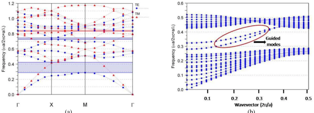
Fig. 3. Band diagram of hexagonal rods in square lattice structure (a) without introducing any defects (1×1 PC-unit cell) (b) after the introduction of defects (21×21 PC-super cell).
(a) (b)
Fig. 4. Band diagram of square rods in square lattice structure (a) without introducing any defects (1×1 PC-unit cell) (b) after the introduction of defects (21×21 PC-super cell).
TABLE I.FREQUENCY AND WAVELENGTH RANGE OF TE/TMPBG OF CIRCULAR,HEXAGONAL AND SQUARE RODS.
Rod Shape PBG Frequency (a/λ) Wavelength Range
(nm)
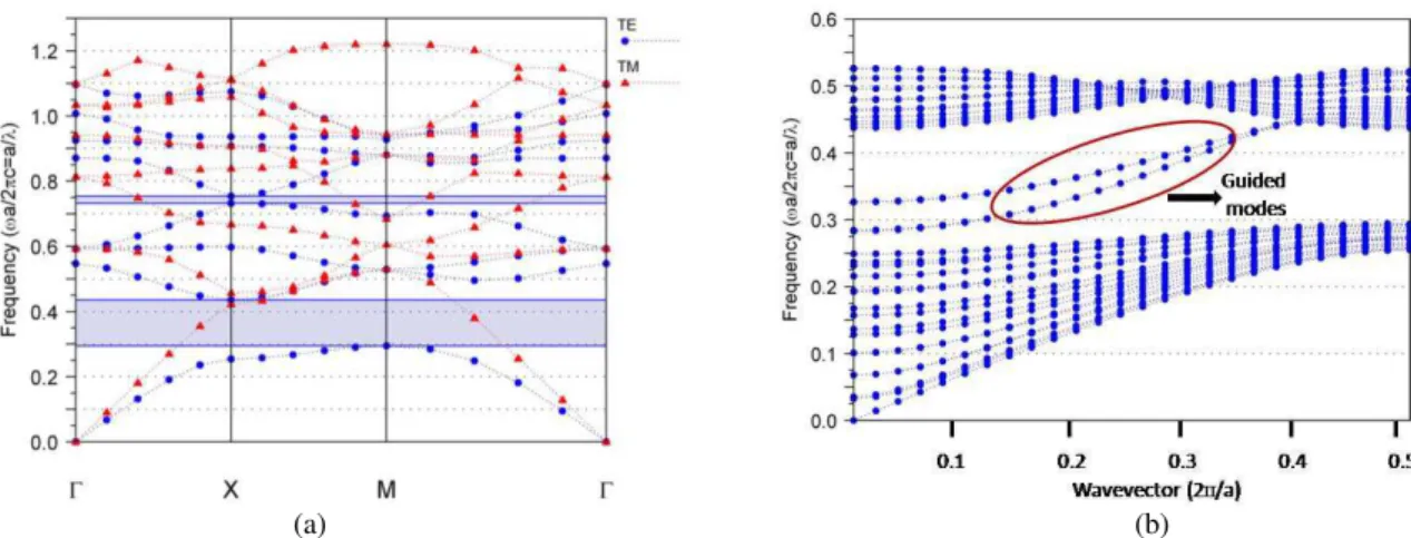
Circular Rods TE 0.295-0.436 1238-1830
0.7315-0.7535 716-738
Hexagonal Rods TE
0.2875-0.4245 1272-1878
0.7245-0.745 724-745
TM 0.8315-0.8435 640-649
Square Rods TE
0.2675-0.384 1406-2018
0.5122-0.5415 997-1054
TM 0.7645-0.778 694-706
The band diagram shown in Figs. 1 (a), 2 (a) and 3 (a) give the propagation modes and TE/TM PBG
present in the 1×1 PC structure of circular, hexagonal and square rods in the square lattice structure,
respectively. They have (both) TE and TM PBG. The TE/TM PBGs with normalized frequencies and
their corresponding wavelength range for circular, hexagonal and square rods are listed in Table I,
is parallel to the rod axis) PBG covers the third window of optical communication, hence, it is
considered here for designing ADF.
The band diagram after the introduction of line and point defects (21×21 PC) with circular,
hexagonal and square rods is clearly pictured in Figs. 1 (b), 2 (b) and 3 (b), respectively. It is
envisaged that, the introduced defects permit the guided modes to propagate inside this PBG region
that contributes the resonance. This peculiar behavior is used here to design the PCRR based ADF.
III. PHOTONIC CRYSTAL RING RESONATOR BASED ADF AND CALCULATION OF FILLING FRACTION
A. Photonic Crystal Ring Resonator based ADF
In general, a ring resonator is positioned between two optical waveguides to provide an ideal basic
structure for ADF. The PCRR based ADF (see in Fig. 1) consists of two waveguides in horizontal
(г-x) direction and a circular PCRR is placed between them. The top waveguide is called as bus
waveguide whereas bottom waveguide is termed as dropping waveguide. The input signal port is
marked as ‘A’ with arrow in the top (bus) waveguide. The ports ‘C’ and ‘D’ of bottom (drop)
waveguide are the drop terminals and denoted as forward dropping and backward dropping terminals,
respectively, while the port ‘B’ of the top waveguide is defined as the forward transmission terminal.
The bus waveguide is formed by introducing line defects and the circular PCRR is shaped by point
defects.
The PCRR is constructed by varying the position of inner rods and outer rods from its original
position towards center. The inner rods are built by varying the position of adjacent rods in the four
sides, from its center, by 25%, whereas the outer rods are constructed by varying the position of
second rod in the four sides, from its center, by 25% in both ‘X’ and ‘Z’ directions where ‘X’ is the
horizontal direction and ‘Z’ is the vertical direction. The number of rings that is formed by the inner
rod is three. The rods inside the circular PCRR are called inner rods whereas the outer rods are
positioned around the inner cavity. The coupling rods are placed between circular PCRR and
waveguides. The scatterer rod (‘s’) is placed in each corner of the ring resonator with half lattice
constant which is used to enhance the performance of the ADF by reducing the counter propagation
modes at resonance and off resonance. The material properties, size and shape of the scatterer rods are
similar to other rods [27].
At resonance, the power is coupled from the bus waveguide into the dropping waveguide through
resonator and exits through one of its output ports. The coupling and dropping efficiencies are noted
by monitoring the power at ports ‘B’ and, ‘C’ & ‘D’, respectively. In order to maximize the output
power efficiency, the cavity has to support two degenerating modes with odd and even symmetry with
respect to an axis which is orthogonal to the waveguides [28]. The designed structure has two guided
B. Calculation of Filling Fraction
The number of rods used in ‘X’ and ‘Z’ directions is 21, for all the three structures, which
determines the filling factor in turn the foot print of the ADF. The foot print for these three structures
is same. The filling factor is the number of rods placed in the structure. The filling fraction is defined
as the space occupied by rods in a lattice which is nothing but the area covered by rods in the lattice.
Since, we have considered circular, hexagonal and square rods, the area of single rod and all rods in
the structure are calculated primarily by using the basic formulae of the respective geometry.
The value of radius (r), width (w) and area (a) for circular, hexagonal and square rods are 0.1 µm,
0.2 µm and 0.2 µm, respectively. The calculated area of single rod and the filling fraction of the
structure with defects, overall area of the structure in square lattice and percentage of filling fraction
are listed in the Table II.
TABLE II.AREA OF THE SINGLE ROD,FILLING FRACTION OF THE STRUCTURE AFTER THE INTRODUCTION OF DEFECTS,AREA OF
THE STRUCTURE AND PERCENTAGE OF FILLING FRACTION OF CIRCULAR,HEXAGONAL AND SQUARE ROD SHAPES.
Rod shape Number of rods in the structure
Area of single rod (sq.m)
Filling Fraction after the Introduction of
Defects (sq.m)
Area of the Square Lattice
(sq.m)
Filling Fraction (%)
Circular Rods 379 0.0314 ×10⁻¹² 11.9006 ×10⁻¹² 129.96 ×10⁻¹² 9.15712
Hexagonal Rods 379 0.0346 ×10⁻¹² 13.1134 ×10⁻¹² 129.96 ×10⁻¹² 10.09033
Square Rods 379 0.04 ×10⁻¹² 15.16 ×10⁻¹² 129.96 ×10⁻¹² 11.66512
The total number of rods in the structure is 441 (21×21) and the number of rods that are removed
while introducing the defects is 66, hence, the total number of rods in the structure after the
introduction of line and point defects becomes 375. In order to enhance the output performance of the
filter, four scatterer rods are also inserted at each corner of the ring which reduces the counter
propagation modes. Finally, the total number of rods in each of the structures after the introduction of
defects comes to 379. The area of single rod is computed and then that is multiplied by 379 to get the
filling fraction of the structure. It is very clear from the Table II that the filling fraction of the
structure using square rod is relatively high while comparing filling fraction of other rod shapes.
IV. SIMULATION RESULTS AND DISCUSSIONS
A Gaussian input signal is launched into the input port. The normalized transmission spectra are
obtained at ports ‘B’, ‘C’ and ‘D’ by conducting Fast Fourier Transform (FFT) of the fields that are
calculated by 2D FDTD method. The input and output signal power is recorded by power monitors
which are positioned at the input and output ports. The normalized transmission is calculated through
1 / 2
( ( )
).
( )
monitor
real p f
dS
T f
SourcePower
=
∫
(1)
Where T(f) is a normalized transmission as a function of frequency, p(f)monitor represents Poynting
vector monitored by the power monitor at the output port of the device and dS is the surface normal.
The further normalization at the output side does not affect the result because of the source power
normalization
.
Finally, the T(f) is converted as function of wavelength.Fig. 5 (a) and (b) depict the normalized transmission spectra of square rod based ADF without
scatterer rods and with scatterer rods. It is clear from that the coupling efficiency, dropping efficiency,
and Q factor of the ADF without scatterer rods becomes low owing to the scattering at corners at
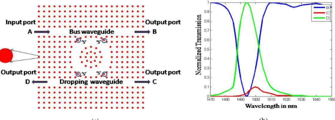
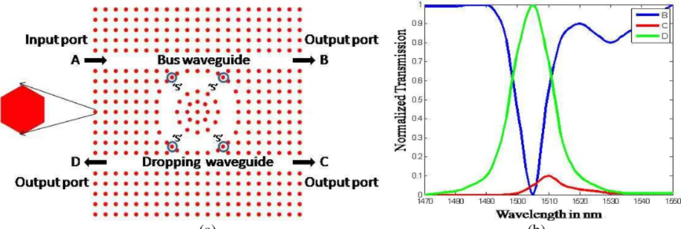
resonance condition. The schematic structure and normalized transmission spectra of circular and
hexagonal rods based ADF are shown in Figs. 6 (a) and (b), and Figs. 7 (a) and (b), respectively. The
resonant wavelength of circular, hexagonal and square rod shape based ADF is 1494 nm, 1504 nm
and 1520 nm, respectively, whose corresponding filling fraction is 11.9006 × 10⁻¹² sq.m, 13.1134 ×
10-12 sq.m and 15.16 × 10⁻¹² sq.m. The total area of the square lattice is 129.96 × 10⁻¹² sq.m.
(a) (b)
Fig. 5. Normalized transmission spectra of PCRR based ADF using square rods (a) without scatterer rods and (b) with scatterer rods .
(a) (b)
(a) (b)
Fig. 7. Schematic structure and normalized transmission spectra of circular PCRR based ADF with hexagonal rods.
Although, shape of the cavity, size of the ring resonator and number of rods in the considered
structure are same, the resonant wavelength is not same for all the filters owing to unique filling
fraction. The different rod shapes of the structure provide unique filling fraction inturn resonant
wavelength. Since, the filling fraction of hexagonal and square rod based structure is higher than
circular rod which results the resonance to occur at longer wavelength with trivial reduction in
performance. Additionally, the response of the result has clearly shown that the circular and
hexagonal rod shape provide 100% (±0.02%)coupling and dropping efficiencies and their Q factor is
124.5 and 107.4, respectively, which are meeting the requirements for ITU-T G. 694.2 eight channel
Coarse Wavelength Division Multiplexing (CWDM) system [29] for optical networks and integrated
optics. The Q factor is defined as the ratio of the resonant wavelength of the ADF to full width half
maximum (λ/∆λ). The resonant wavelength, coupling and dropping efficiencies, passband width and
Q factor of square, circular and hexagonal rod based ADFs without and with scatterer rods are listed
in the Table III.
TABLE III.RESONANT WAVELENGTH,COUPLING AND DROPPING EFFICIENCIES,PASSBAND WIDTH AND QFACTOR OF SQUARE,
CIRCULAR AND HEXAGONAL RODS
Rod shape Resonant
Wavelength (nm)
Coupling Efficiency (%)
Dropping Efficiency (%)
Passband
Width (nm) Q factor
Circular Rods a* 1497 98 80 15 99.8
b* 1494 100 100 12 124.5
Hexagonal Rods a* 1507 98 90 17 88.6
b* 1504 100 100 14 107.4
Square Rods a* 1523 95 75 19 80.15
b* 1520 98 96 16 95
a* without scatterer rods; b* with scatterer rods
(a) 1520 nm (b) 1540 nm (c) 1494 nm
(d) 1515 nm (e) 1504 nm (f) 1525 nm
Fig. 8. Electric filed pattern of pass and stop region of ADF based on square rod (a) & (b), circular rod (c) & (d), and hexagonal rod (e) & (f).
The Figs. 8 (a) and (b), (c) and (d), and, (e) and (f) depict the electric filed pattern of pass region
and stop region of square, circular and hexagonal rods based ADF with scatterer rods. It shows that, at
resonant wavelength the electric field from the bus waveguide is coupled into the ring and reached
into one of its output ports, whereas at ‘off’ resonance the signal reaches the transmission terminal. It
is also noted that certain part of signal power (1% to 8% which is neglighle) is reaching the other
ports at “off” resonance owing to the scattering.
A. Effect of variation in filling fraction
To investigate the effect of resonant wavelength with respect to filling fraction, the variation in rod
radius (ciruclar and hexagonal) and width of the rod (square) are accounted. Here, the radius (width)
of the rods in the structure is varied from 0.09 (0.18) µm to 0.11 (0.22) µm with 0.02 (0.04) µm
uniform step value. Increase in uniform step value of structural parameters, the filling fraction of the
structure and area of the single rod of circular, hexagonal and square rod based ADF structure are
increased by 0.4737×10⁻¹² sq.m, 0.5343×10⁻¹² sq.m and 0.6046×10⁻¹² sq.m, and 0.00125×10⁻¹² sq.m,
0.00143×10⁻¹² sq.m and 0.0016×10⁻¹² sq.m, respectively.
Fig. 9 (a) shows the variation of resonant wavelength with respect to radius (width) of the rods for
different rod shape based ADF. The variation in overall filling fraction while variing the radius is
9.6266 ×10⁻¹² sq.m to 14.3641×10⁻¹² sq.m (circular), 10.5362×10⁻¹² sq.m to 15.8801×10⁻¹² sq.m
(hexagonal) and 12.2976×10⁻¹² sq.m to 18.3436×10⁻¹² sq.m (square) whose corresponding resonant
wavelength variation is 1475 nm to 1513 nm (circular), 1485 nm to 1526 nm (hexagonal) and
1497 nm to 1547 nm (square). It clearly shows that there is linear resonant wavelength shift into
longer wavelength while increasing the radius (width) of the rod inturn filling fraction. The filter
parameters (coupling and dropping efficiencies, passband width and Q factor) are not affected as
much at lower filling fraction. However, there is significant change noted at higher filling fraction.
The resonant wavelength shift for every increase in step value of radius for circular, hexagonal and
width for square rod is given below:
∆λ / ∆r = 3.8 nm / 0.02 µm (for circular rods)
∆λ / ∆r = 4 nm / 0.02 µm (for hexagonal rods)
where ∆λ is the shift in resonant wavelength, ∆r is the change in radius of the rod and ∆w is the
change in width of the rod.
(a) (b)
Fig. 9. Effect of resonant wavelength for (a) variation of radius (width) of the rod and (b) variation in filling fraction for different rod shapes based structure [0.09 µm is the radius of the circular and hexagonal rods which is equal to 0.18 µm for
sqaure rods].
Fig. 9 (b) presents the comparison of resonant wavelength with the variation of overall filling
fraction for all rod shapes. It reveals that there is a linear relationship between the resonant
wavelength and filling fraction irrespective of the shape of the rod and also while varying the cross
sectional dimension of the rod, even the ranges of overall filling fraction is unique for different rod
shapes. It is concluded that there is 1 nm wavelength shift in resonant wavelength is observed for
every changing overall filling fraction of 0.1233 × 10⁻¹² sq.m and area of single rod by
0.0033 × 10⁻¹² sq.m.
The effect of resonant wavelength and functional parameters of the filters are examined in detail
with respect to the variation of filling fraction with the assumption that the structure is made up of
only one type of rod shape. Interestingly, a linear relation between filling fraction and resonant
wavelength is noticed and after conducting detailed study the rate of shift is also quantified in the
previous sections. In continuation with that the authors like to explore the behavior of resonance of
the structure/filter when the structure is made up of more than one type of rod shapes.
As there are three rod shapes and two portions of the structure (inner and scatterer rod) are
considered, many combinations are possible with rod shape and place of positioning. Among them,
six different combinations are only accounted for this investigation. The details of the filling fraction
with the corresponding resonant wavelength of circular rod based structure with different rod shapes
are listed in Table IV. As expected, the resonant wavelength shift is linear while varying the filling
fraction irrespective of rod shape. The similar analysis is also carried out by keeping hexagonal and
square rods in the structure with different rod shapes in inner and scatterer rods whose corresponding
details are tabularized in Table V and Table VI. Though, the change in filtering performance of this
structure is trivial, there is a linear relationship noticed between resonant wavelength and filling
TABLE IV. FILLING FRACTION AND ITS RESONANT WAVELENGTH OF DIFFERENT ROD SHAPES IN A CIRCULAR ROD BASED
STRUCTURE
Rod shapes Filling Fraction
of the Structure (sq.m) Filling Fraction (%) Resonant Wavelength (nm) Base
structure Inner Rod Scatterer Rod
Circular
Circular Circular 11.9006×10⁻¹² 9.1571 1494
Hexagonal Circular 11.9678×10⁻¹² 9.2088 1498
Hexagonal Hexagonal 11.9806×10⁻¹² 9.2186 1499
Hexagonal Square 12.0022×10⁻¹² 9.2353 1501
Square Circular 12.0812×10⁻¹² 9.2960 1504
Square Hexagonal 12.0940×10⁻¹² 9.3059 1506
Square Square 12.1156×10⁻¹² 9.3225 1507
Finally, while increasing the filling fraction the resonant wavelength linearly shifts into the longer
wavelength and vice-versa. By choosing appropriate values, it is possible to add or drop any one of
the desired channels of ITU-T 694.2 CWDM [27] systems. The center wavelength, channel spacing
and passband width of this standard are, 1471 nm to 1611 nm, 20 nm and 13 nm±1.5 nm, respectively.
TABLE V. FILLING FRACTION AND ITS RESONANT WAVELENGTH OF DIFFERENT ROD SHAPES IN A HEXAGONAL ROD BASED STRUCTURE
Rod shapes Filling Fraction
of the Structure (sq.m) Filling Fraction (%) Resonant Wavelength (nm) Base
structure Inner Rod Scatterer Rod
Hexagonal
Hexagonal Hexagonal 13.1134×10⁻¹² 10.0903 1504
Circular Circular 13.0334×10⁻¹² 10.0287 1499
Circular Hexagonal 13.0462×10⁻¹² 10.0386 1501
Circular Square 13.0678×10⁻¹² 10.0552 1502
Square Circular 13.2140×10⁻¹² 10.1677 1510
Square Hexagonal 13.2268×10⁻¹² 10.1775 1511
Square Square 13.2484×10⁻¹² 10.2484 1513
TABLE VI. FILLING FRACTION AND ITS RESONANT WAVELENGTH OF DIFFERENT ROD SHAPES IN A SQUARE ROD BASED
STRUCTURE
Rod shapes Filling Fraction
of the Structure (sq.m) Filling Fraction (%) Resonant Wavelength (nm) Base
structure Inner Rod Scatterer Rod
Square
Square Square 15.1600×10⁻¹² 11.6651 1520
Circular Circular 14.9450×10⁻¹² 11.4996 1513
Circular Hexagonal 14.9578×10⁻¹² 11.5095 1514
Circular Square 14.9794×10⁻¹² 11.5261 1516
Hexagonal Circular 15.0122×10⁻¹² 11.5514 1517
Hexagonal Hexagonal 15.0250×10⁻¹² 11.5612 1518
Generally, there are two types of loss mechanism occurring in photonic crystal based devices (a)
Intrinsic loss which accounts the loss inside the cavity (absorption and out of plane scattering and
material loss due to surface roughness and material imperfection) and (b) Extrinsic loss which
accounts for the energy leakage of the cavity due to the coupling with the waveguide and ring
resonator. Owing to these losses in this type of structure, the variation (tolerance) of the resonant
wavelength shift is acceptable (as the performances of the device is not detoriating much) by as much
as 2.5 % to 5 % from the nominal value [30]. Though, the fabrication of hexagonal shape rods is little
bit difficult and fabrication losses also higher than circular and square shape rods, the fabrication loss
can be minimized by selecting the proper fabrication technique [31, 32].
V. CONCLUSIONS
The performance of Two Dimensional circular Photonic Crystal Ring Resonator based Add Drop
Filter is investigated by designing ADF with different rod shapes i.e., circular, hexagonal and square
rods and varying the radius/width (filling fraction) of the rods. The filter parameters such as resonant
wavelength, coupling efficiency, dropping efficiency, passband width and Q factor of different rod
shape based ADF is investigated and compared. The resonant wavelength of the filter is not same for
all the rod shape due to unique filling fraction. The relative filling fraction (%) and resonant
wavelength of a circular, hexagonal and square rod based structures are 11.9006 ×10⁻¹² sq.m (9.15%),
13.1134 ×10⁻¹²sq.m (10.09%) and 15.16 ×10⁻¹² sq.m (11.66%) and 1494 nm, 1504 nm and 1520 nm,
respectively. It is concluded that there is 1 nm wavelength shift is observed while increasing the
overall filling fraction by 0.1233×10⁻¹² sq.m (0.0948%) and rod filling fraction by
0.0033 ×10⁻¹²sq.m (0.0025%). Also, the filling fraction of homogeneous and heterogeneous structure
is linearly depending on the resonant wavelength. Approximately, 3.8 nm, 4 nm and 5 nm resonant
wavelength shift is observed for every changing radius (0.02 µm) / width (0.04 µm) of circular,
hexagonal and square rods. Close to, 100% of coupling and dropping efficiencies are observed for
circular and hexagonal rod based ADF whose Q factor is 124.5 and 107.42, respectively. Hence, the
authors recommend both circular and hexagonal rod geometry for the design of PCRR based ADF to
get better results.
REFERENCES
[1] Dan Sadot, and Efraim Boimvich, “Tunable optical filters for dense WDM networks”, IEEE Communication Magazine, vol. 36, no. 12, pp. 50-55, 1998.
[2] E. Yablonovitch., “Inhibited spontaneous emission on solid-state physics and electronics”, Phys. Rev. Lett., vol. 58, no.20, pp. 2059-2062, 1987.
[3] S. John, “Strong localization of photons in certain disordered dielectric superlattices”, Phys. Rev. Lett., vol. 58, no. 23, pp. 2486-2489, 1987.
[4] J. D. Joannopoulos, R. D. Meade, and J. N. Winn, “Photonic crystal: Modeling of flow of light”, Princeton, NJ: Princeton university press, 1995.
[5] J. D. Joannopoulos, P. R. Villeneuve, and S. Fan, “Photonic crystals: putting a new twist of light”, Nature, vol. 386, pp. 143-149, 1997.
[6] A. Ghaffari, F. Monifi, M. Djavid, and M. S. Abrishamian, “Analysis of photonic crystal power splitters with different configurations”, Journal of Applied Science, vol. 8, no.8, pp. 1416-1425, 2008.
[8] A. Ghaffari, F. Monifi, M. Djavid, and M. S. Abrishamian, “Heterostructure wavelength division demultiplexers using photonic crystal ring resonators”, Optics Communications, vol. 281, n0. 15-16, pp. 4028-4032, 2008.
[9] V. Zabelin, L. A. Dunbar, N. Le Thomas, R. Houdre, M. V. Kotlyar, L. O’Faolain, and T. F. Krauss, “Self-collimating photonic crystal polarization beam splitter”, Optics Letters, vol. 32, no. 5, pp. 530-532, 2007.
[10] Tien-Tsorng shih, Yaw-Dong Wu, and Jian-Jang Lee, “Proposal for compact optical triplexer filter using 2-D Photonic crystals”, IEEE Pho. Tech. Lett., vol. 21, no. 1, pp. 18-21, 2009.
[11] Qiong Wang, Yiping Cui, Hiayu Zhang, Changchun Yan, and Lingling Zhang, “The position independence of heterostructure coupled waveguides in photonic-crystal switch”, Optik Optics, vol. 121, no. 8, pp. 684-688, 2010. [12] M. K. Moghaddam, A. R. Attari, and M. M. Mirsalehi, “Improved photonic crystal directional coupler with short
length”, Photonics and Nanostructures-Fundamentals and Applications, vol. 8, no. 1, pp. 47-53, 2010.
[13] S.Robinson, and R. Nakkeeran, “Bandstop filter for photonic integrated circuits using photonic crystal with circular ring resonator”, SPIE Journal of Nanophotonics, vol. 5, pp. 053521-1-13, 2011.
[14] M. Djavid, A. Ghaffari, F. Monifi, and M. S. Abrishamian, “Photonic crystal narrow band filters using biperiodic structures”, Journal of Applied Science, vol. 8, no. 10, pp. 1891-1897, 2008.
[15] S. Robinson, and R. Nakkeeran, “Investigation on two dimensional photonic crystal resonant cavity based bandpass filter”, Optik Optics, vol. 123, no. 5, pp. 451-457, 2012.
[16] S. Fan, P. R. Villeneuve, J. D. Joannopoulos, and H. A. Haus “Channel drop filters in photonic crystals”, Opti. Express, vol. 3, no. 1, pp. 4-11, 1998.
[17] Chun-Chih Wang, and Lien-Wen Chen, “Channel drop filters with folded directional couplers in two-dimensional photonic crystals”, Physica B, vol. 405, no. 4, pp. 1210-1215, 2010.
[18] M. Djavid, A. Ghaffari, F. Monifi, and M. S. Abrishamian, “T-Shaped channel drop filters using photonic crystal ring resonators”, Physica E, vol. 40, no. 10, pp. 3151-3154, 2008.
[19] B. S. Darki, and N. Granpayesh, “Improving the performance of a photonic crystal ring-resonator-based channel drop filter using particle swarm optimization method”, Optics Communications, vol. 283, no. 20, pp. 4099-4103, 2010.
[20] Z. Qiang, W. Zhou, and Richard A. Soref, “Optical add-drop filters based on photonic crystal ring resonators”, Opti. Express, vol. 15, no. 4, pp. 1823-1831, 2007.
[21] Juan Jose Vegas Olmos, Masatoshi Tokushima, and Kenichi Kitayam, “Photonic add–drop filter based on integrated photonic crystal structures”, Journal of Selected Topics in Quantum Electronics, vol. 16, no. 1, pp. 332-337, 2010. [22] M. Djavid, A. Ghaffari, F. Monifi, and M. S. Abrishamian, “A new broadband photonic crystal add drop filter”,
Journal of Applied Sciences, vol. 8, no. 11, pp. 2178-2182, 2008.
[23] Trong Thi mai, Fu-Li Hsiao, Chengkuo Lee, Wenfeng Xiang, Chii-Chang Chen, and W. K. Choi, “Optimization and comparison of photonic crystal resonators for silicon micro cantilever sensors”, Sensors and Actuators A: Physical, vol. 165, no. 1, pp. 16-25, 2011.
[24] A. A. M. Kok, J. J. G. M. Van der Tol, M. K. Roel Baets and Smit, “Reduction of propagation loss in pillar-based photonic crystal waveguides”, Journal of Lightwave Technology, vol. 27, no. 17, pp. 3904-3911, 2009.
[25] S. Robinson, and R. Nakkeeran, “Photonic Crystal Ring Resonator Based Add-Drop Filter Using Hexagonal Rods for CWDM Systems, Optoelectronics Letters, vol. 7, no. 3, pp. 164-166, 2011.
[26] A. Lavrinenko, P. I. Borel, L. H. Frandsen, M. Thorhauge, A. Harpoth, M. Kristensen, T. Niemi, and H. M. H. Chong, “Comprehensive FDTD modeling of photonic crystal waveguide components”, Opti. Express, vol. 12, no. 2, pp. 234-248, 2004.
[27] V. Dinesh Kumar, T. Srinivas, and A. Selvarajan, “Investigation of ring resonators in photonic crystal circuits”,
Photonics and Nanostructures-Fundamentals and Applications, vol. 2, no. 3, pp. 199-206, 2004.
[28] C. Manolatou, M. J. Khan, S. Fan, P. R. Vileneuve, H. A. Haus, and J. D. Joannopoulos, “Coupling of modes analysis of resonant channel add-drop filters,” Journal of Quantum Electronics, vol. 35, no. 9, pp. 1322-1331, 1999.
[29] ITU-T Recommendation G 694.2, Spectral grids for WDM applications: CWDM wavelength grid.
[30] Kartik Srinivasan, P. E. Barclay, and O. Painter, “Fabrication tolerant high quality factor photonic crystal microcavities”, Optics Express, vol. 12, no. 7, pp. 1458-1463, 2004.
[31] M. Walker, M. Cryan, Patric Strasser, and Kartik Srinivasan, “Fabricating photonic crystals in InP”, III Vs Review the advanced semiconductor magazine, vol. 18, no. 5, pp. 46-49, 2005.