Employing Integrated Logic Analysers and
Virtual I/Os to Verify Soft Core Protocol
Implementations
I.Sheikh, and M. Short
∗Abstract—This paper will discuss the use of In-tegrated Logic analysers (ILAs) and Virtual I/Os (VIOs) to verify the behavior of soft core protocol implementations. In particular, a soft core implemen-tation of the Controller Area Network (CAN) proto-col will be used as a representative example to dis-cuss the use of the proposed scheme. The paper will describe a procedure such that VIO and ILA may be employed to conduct low-cost conformance testing against specific test plans, both for the generation of test patterns and the verification of the resulting im-plementation behavior. As will be shown, VIOs are particularly helpful in generating high-frequency bit patterns, and may be used to great effect as a flexi-ble bench pattern generator; the generated patterns make use the same system clock as the unit under test, and thus allow for tighter control of timing and more precise pattern generation. When coupled with suitable ILAs, such as the simple analysis tool Chip-scope, it will be argued that such a scheme allows for a highly flexible and low-cost approach to proto-col verification. Finally, we describe the use of a test bed in the verification of an open-source CAN soft core implementation against the relevant ISO testing standards.
Keywords: CAN, Conformance Testing, Chipscope VIO, Pattern Generation, Soft Core, Digital Commu-nications
1
Introduction
Conformance testing is an integral part of any protocol development. Conformance testing essentially verifies the behavior and capabilities of a protocol implemen-tation against the requirements and ideal behaviors as set out in a specific standard [1]. Traditionally, the implementation of protocol conformance testers has been a somewhat proprietary activity, employing dedicated hardware and analysis software especially written for the
∗Manuscript submitted 29th
September 2009. This paper is part of Imran Sheikh PhD work funded by UET Peshawar, Pakistan. I. Sheikh is currently with Embedded Systems Lab, Engineering De-partment, University of Leicester UK. Tel: 44-116-252/2578 Email: [email protected]. Michael Short is a Lecturer in Engineering Depart-ment, University of Leicester, UK. Tel: 44-116-252/5052 Email: [email protected].
protocol and device under test. This is clearly a practical approach when testing and verifying device conformance prior to high-volume IC manufacture. However, recent years have seen resurgence and increased interest in the use of protocol implementations achieved by the use of programmable hardware devices such as FPGAs.
By their very nature, such soft core implementations are often needed in small-volume (or even one-off) batches; these implementations may even add additional or cus-tom functionality to existing protocols (e.g. see [2, 3]). In these circumstances, cost and availability reasons often dictate that it is not practical for developers to use traditional conformance testing equipment.
However when a protocol is implemented in such a soft core form which is an initial re-synthesizable design independent of any specific technology, it is clearly still necessary to test its functionality against the relevant standards. FPGAs and the associated Hardware De-scription Languages (HDLs) for use with them have made it comparatively easy to translate any logic into a design reality, while also keeping the design flexible and customizable; in many aspects, a HDL resembles a traditional programming language. For this reason, many of the features of traditional approaches to con-formance testing become redundant; alternative, flexible and cheaper techniques are sought for their replacement, and this is one of the primary motivations for this paper. Hence many different complex designs some consisting of multiprocessor clusters, DSPs and complete commu-nication protocols - have been implemented as soft cores on programmable devices. Soft-core implementations for non-real-time communication protocols such as Ethernet IP Core [4], SIP processor [5] along with embedded and real-time protocols such as Controller Area Network (CAN) [2] and Flex Ray [6] are several examples of protocols that have been successfully implemented.
implementation, then conformance testing of said pro-tocol also becomes a requirement; this may complicate matters further. According to a recent survey by Lai, a conformance test method must be evaluated using three principles [8]. Firstly, the IUT (implementation under Test) behavior must be comparable to the precise proto-col definition; secondly a comprehensive test suite must be present covering all the aspects of protocol function-ality. Finally, a test system which provides a controlled and reproducible environment for test implementation is required. This paper is mostly concerned with the third aspect, and will propose a simple, reproducible and cost effective testing environment for use with soft core implementations. The main features of this test environment will be illustrated using a representative example, a soft core implementation of the CAN protocol.
The remainder of the paper is organized as follows. Sec-tion II will first briefly review the process of protocol conformance testing, and will outline the proposed test-ing environment for use with soft core implementations. Section III will then describe the CAN protocol, and ex-isting approaches to CAN conformance testing both be-fore and after the relevant ISO test standard evolved. Section IV describes a test facility that has been devel-oped to implement the proposed testing environment for CAN conformance testing. Section V then presents a se-ries of detailed case studies, involving four separate tests designed to illustrate some of the features of the pro-posed environment. Section VI presents an analytical comparison of the approach with alternate techniques for conformance testing. Section VII concludes the paper.
2
Conformance Testing of Softcore
Pro-tocols
The test and verification of a soft core as either an in-dividual entity - or as a system level entity - in a SoC design is clearly of major importance in complex elec-tronic systems. Design for Test (DFT) techniques such as Built In Self Test (BIST) and Automatic Test Pattern Generation (ATPG) /Scan are primarily used for design testability of soft cores. ATPG techniques are typically user modifiable; the testing cores are typically inserted at any time of the design phase. Although much work has been done on the effective use of BIST cores [9] they are limited in the sense that only the logic integrity of the soft core as opposed to the functionality of the soft core can be tested. However, protocol conformance testing requires that both the logic and functionality of a can-didate design are verified. Before describing the scheme to support this process as presented in this paper, sev-eral gensev-eral approaches to conduct test and verification of protocol implementations on standard (silicon-based) targets will be described.
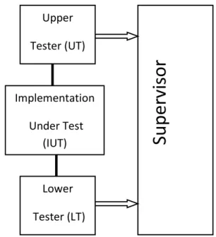
Figure 1: ISO 9646-1 Test Plan Architecture.
2.1
Protocol Conformance Testing
A standard conformance test suite is normally employed to indicate anomalies in a given protocol implementa-tion, and the methodologies by which these test suites are applied to the Implementation Under Test (IUT) are not unique and vary depending on the suite in question. For example, IEEE 1802.3 [10], [11] provides documents outlining the conformance testing standards of a well know protocol Suite IEEE 802 [12] for LAN (Local Area Network) communication. However, these documents do not specify a unique procedure to conduct these tests; it is up to the tester to adopt any such method of convenience to run these conformance tests under a guideline. One such guideline is provided by ISO 9646-1 [1] which states a layered approach to test a protocol; hence the Test Plan (TP) is adaptable to the layer under test, i.e. we can use the same TP to verify the lower layers such as physical layer testing (such as transceiver functionality or interface stan-dards), and also employ a similar TP to verify the data layer/MAC functionality of a communication protocol. The adaptability of the TP depends upon the use of both appropriate hardware and software. The TP outlined in this standard is shown in Figure 1, and indicates that the tester is divided into two testing blocks and a Supervisor.
the IUT [11]. The UT receives stimulus (with details of the test being performed) from the LT, and generates messages passed on to the IUT. The IUT then processes these messages, and both the UT and LT components monitor its behavior for consistency with the protocol under test. The results are passed to the tester supervi-sor for verification, and if the result is satisfactory, the test is considered passed and testing proceeds to the next conformance test. It should be noted that the testing procedures that are required to be implemented include coverage of common error conditions, randomized tests and also bit timing tests. Most tests are critical, and the latter category bit timing contains a number of tests that can be difficult to localize, and a suitable means is required to capture and display multiple logic signals over an appropriate timescale. This typically requires the use of dedicated hardware and Logic analysers [13].
Another example of conformance testing implementation which has also tried to follow the ISO 9646-1 TP is described by Lee et al. [14]. This work describes con-formance testing of the communication protocol IEEE 1284 [15] - implemented by a soft-core and has been achieved by firmware running in a PC to monitor the test results. An ARM processor is used to work as a host or UT, while the PC acts as the LT, which generates the test cases and also verifies the outcome from the IUT. This implementation is able to provide the successful transmission/reception of the messages, but problem with this type of testing setup is the unavailability of the precise timing of the signal states.
Another example of Conformance testing can be taken form Xilinx itself which have done there Ethernet protocol implementation on an FPGA and conformance testing [16] has been done in accordance UNH IOL [17] standard for IEEE 802.3 MAC Conformance Tests from 1Mbps to 10 Gbps. The Test plans used in this example also follow the ISO 9646 TP and use of Chipscope ILA is there but again with the addition of specialized hardware and proprietary firmware to conduct these tests.
These two examples are of methods to conduct confor-mance testing of the protocols under consideration but are rather complex, expensive or proprietary but our aim is to find a cost effective and a general solution which can even be carried out for one-off or small volume im-plementations.
2.2
Proposed Environment
As discussed earlier, the use of HDLs for soft-core im-plementations requires verification; generally speaking, pure simulation methods - and also formal verification techniques applied solely to the HDL code - cannot
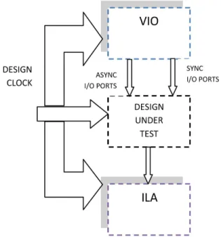
pro-Figure 2: ISO 9646-1 Test Plan Architecture.
vide a guarantee that the HDL code has been correctly translated and implemented on the target hardware (FPGAs), and is working as desired. Since the design inside an FPGA is tightly integrated (encompassing several components into a single FPGA) - and unlike designs with hardwired components - most of the signals are inter-wired and are unavailable on the external ports for observation. Hence there is an important requirement for tools which can analyse these signals, and most FPGA manufacturers have designed on-chip debug tools for this purpose. These tools provide full internal visibility using Integrated Logic analysers (ILAs) such as Signal Tap [18] and Chipscope pro [19]. These tools provide small and efficient cores to debug not only I/O but also importantly - internal signals can be captured. Such tools normally provide real time system debug support, for example by using a JTAG port. The Chipscope pro from Xilinx is one such tool which provides online on-chip debugging facility. Figure 2 shows how a Design under Test can be attached with Chipscope cores. The cores can either be initiated in the HDL source code manually, or by using core insertion tools provided by the package. The designer can place different cores to the design (described below). These cores do take system resources, but unlike BIST and ATPG they can be easily removed once the design is verified.
In this paper we will be dealing with 3 Chipscope cores:
1. ICON which is the controller core, and provides an interface between the external ports (i.e. JTAG) and the internal cores.
2. ILA is the integrated logic analyser core; all input and output signals requiring observation are con-nected to it.
3. VIO is the Virtual Input Output, which provides Virtual I/Os to the HDL design and can be user ini-tiated at run time. These I/Os can be synchronous or asynchronous to the system clock.
The remainder of this paper will illustrate the use of such an environment to test a soft core implementation of a CAN controller. The following Section describes this pro-tocol in detail, the motivation for developing the soft core, and the need for its verification.
3
CONTROLLER AREA NETWORK
3.1
Protocol description
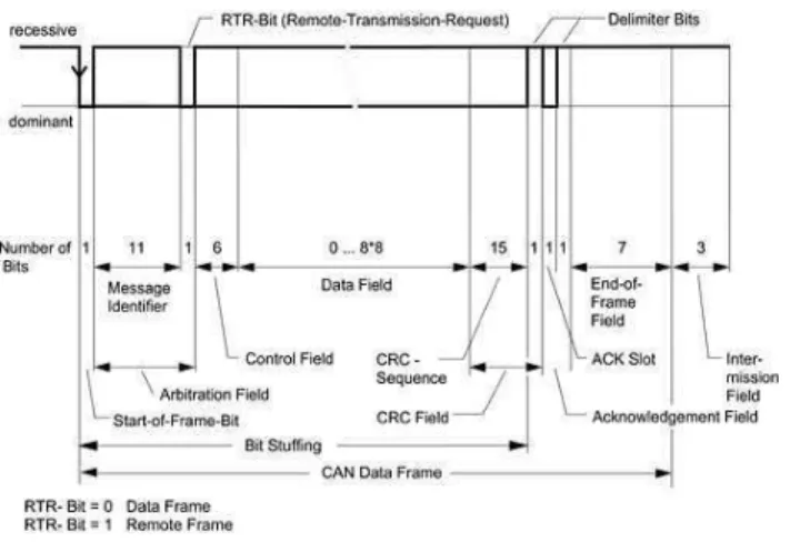
The Controller Area Network (or simply CAN) is one of the most widely employed protocols for creating distributed embedded systems, with applications as far ranging as vehicle electronics, process control and many other important industrial applications [21]. Some of the key features of CAN that have led to its widespread use include low overheads, non-destructive bitwise message arbitration, low message latency and good error detecting abilities; all features which are required for control ap-plications running on embedded processors [22][23]. The structure of a CAN frame is shown in Figure 3. As men-tioned, the protocol employs a unique non-destructive priority-based arbitration scheme; when multiple nodes attempt to transmit messages simultaneously this mech-anism ensures that the highest priority message gains first access to the bus. If priorities are carefully as-signed to the messages, and appropriate timing analysis is performed, CAN may be used to implement several different types of time-critical systems (e.g. see [22]-[24]).
CAN controllers and transceivers have been implemented at the silicon level, either by dedicated ICs or as on-chip peripherals of embedded devices; many such CAN con-trollers are widely available, e.g. [25, 26]. In practice, as with most other silicon-based protocol implementa-tions, the implementation of CAN conformance testers has been done using dedicated hardware and specially written analysis software, which is a practical approach when testing and verifying conformance prior to high-volume IC manufacture. ISO has developed a standard CAN conformance testing document [27], and any device that wishes to claim to be CAN conformant is required to demonstrate evidence that shows the testing procedures outlined in the standard have been performed and passed without problem. The ISO document not only specifies different types of tests that must be performed for confor-mance testing, but also specifies a TP architecture based on the ISO 9646-1 described in the previous Section.
Figure 3: CAN Frame Format.
The wired-AND nature of the physical layer, which is used to achieve the afore-mentioned priority-driven arbi-tration, requires that all nodes in the network achieve a logical consensus on the instantaneous bit-patterns ap-pearing on the bus lines. This particular requirement of the protocol acts to severely limit both the maximum transmission speed and bus length of a given CAN net-work; the maximum transmission rate is inversely propor-tional to the length of the bus, and has an upper limit of 1 MBit/s; due to its design a CAN frame may carry up to a maximum of 8 data bytes. In addition, this mecha-nism places extremely specific requirements on the nature of the conformance testing that must place for a CAN-enabled device; a significant proportion of the ISO test standard is devoted to this single, critical aspect of the protocol.
3.2
CAN Conformance Testing
One of the earliest CAN prototype controllers was named DBCAN [28]. This implementation was tested using a logic analyser and a pattern generator circuit. As there was no standard for conformance testing at the time the prototype was developed, a commercial basic (as opposed to full) CAN controller was used as benchmark for verification. A major disadvantage of this scheme was the use of external interface modules to visualize the state of different DBCAN registers, and the testing procedure was somewhat limited in the number of signal channels that could be simultaneously analysed. Since this is a needed requirement in the case of ISO standard conformance testing the ability to visualize the state of large numbers of CAN registers simultaneously is a prerequisite such a setup is limited in this respect.
the testing plan. Specialized verification architecture for testing automotive protocols (including CAN) at both the module and chip level was proposed by [30]. Again, this work requires a specially designed CAN verification component as part of the silicon, while the selection and implementation of actual test sequences, along with the selection of a suitable means to monitoring bus signals, is left open for the tester.
A Hardware emulation technique was used to verify a CAN soft core in [31]; firstly, the synthesized net list is downloaded into a hardware emulator. This emulator is configured by a PC and the communication between the two is carried via a specially designed interface card connected to the EISA bus; this emulator is also connected to 2 commercially available CAN chips. The drawback with this technique is that again, customized hardware along with software especially written to carry out the conformance testing is required. Additionally, to emulate the bus failures and potential error conditions on the bus a manual technique of connecting CAN bus to the output of individual nodes is employed, which lacks efficiency and is not robust enough to cover all the scenarios given within ISO DIS 16845.
With respect to soft core CAN implementations, the CAN e-Verification (CANeVC) test bench has previously been described [32]. This commercial test facility requires a CAN specification core to be embedded in the netlist; this core then runs specific tests to verify the behavior of the CAN soft core. Again, this technique involves a time consuming development of a test bench using an expensive commercially available verification IP ; addi-tionally, compatibility issues often arise when using CAN implementations other than the proprietary implemen-tation [33], and only a limited number of programmable logic devices are supported. Finally, several experimental implementations (such as that reported by [34]) to mea-sure single parameters - such as CAN bit errors - rather than perform complete conformance testing have been described in the literature. Such implementations have typically used complex and non-trivial means, requiring customized hardware and software. In summary then, it can be observed that - to date specialized hardware and / or software has been required to assist with CAN testing plans.
3.3
Protocol Limitations
However, the CAN protocol itself is not without its drawbacks; although the basic raw protocol is suitable for use in many soft real-time systems, it suffers from sev-eral significant problems with respect to hard real-time systems, for example in safety-critical distributed brake-by-wire systems. These drawbacks include redundancy issues, atomic broadcast problems, lack of protection
from babbling idiot failures and information throughput restrictions. Although research has shown that many of these issues can be dealt with by the creation of higher-level, software-based protocol extensions (e.g. see [22, 23, 35]), some proposed solutions are either complex to implement placing a significant computa-tional overhead on the host CPU or simply cannot be implemented in software and a hardware solution must be adopted [3]. Although the proposed changes are conceptually quite straightforward, implementing them directly in silicon is costly and has proved to be problematic for small-volume requirements. A workable solution to this problem is to implement the protocol on a PLD; the required modifications may then be achieved with relative ease. This solution brings with it another, related problem; before verification of any modifications can take place, it must be shown that the basic soft core CAN implementation is fully conformant to the protocol, a potentially costly and time-consuming procedure in its own right.
To help alleviate this problem, the current authors have previously proposed a low-cost and easily implemented method in two previous works [36, 37]. These papers essentially describe the application of the techniques de-scribed in the previous Section to the conformance of a CAN soft core. This basic approach was subsequently ex-tended in [20], in order to include the test cases related to CAN bit-timing for which the use of VIO was required to complement the existing methods based around the use of ILAs and embedded test pattern generation. The fol-lowing Section contains a description of the test facility that was employed in these studies.
4
TEST BED
4.1
Architecture
As part of ongoing project within the authors research group, the development of a fully-conformant soft core controller for the CAN protocol was required [2]. After the implementation of the CAN specifications for such a controller, it was required to be tested and verified in accordance with the relevant ISO standard [27]. Real-time testing of a CAN implementation is quite a complicated procedure, and in this case for practical reasons, no specialized hardware and software was available to generate the required testing patterns and monitor the behavior of the CAN soft core. For this reason, it was decided to use only low-cost off the shelf components, and a testing environment based on that proposed in Section II was created especially for this purpose. The main components of this test environment are described in the following Sections.
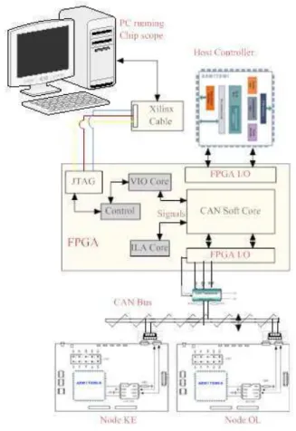
Figure 4: Test Bed.
components used in the test bench will be given; further details are given in [2, 20]. The main components are illustrated graphically in Figure 3.
4.1.1 Hardware
• Two FPGA (XC3S500E programmed with CAN soft core) + ARM7 (LPC2138 as Host controller) boards these boards are named as SC1 and SC2. The pur-pose of using two soft cores is to verify simultaneous behavior as a CAN Transmitter/Receiver as well as to generate special patterns on the CAN bus using VIO and additional soft modules embedded with the soft core.
• Two ARM7 Microcontroller boards with Integrated CAN controller and transceivers. These boards are used as Receivers of CAN messages for further veri-fication of the messages sent by the CAN soft core. In few test cases mentioned in [27] the boards are used to induce errors on the CAN bus.
The Figure 4 demonstrate a 2 node Soft Core, it can easily be extended to n number of nodes.
4.1.2 Software
• Xilinx ISE [38] for soft-core programming, synthe-sis, routing and programming the FPGA. The ISE is a complete IDE for FPGA development and con-tains some extra features like power analysis, optimal routing and timing analysis to name a few.
• Chipscope Pro is used as analysis tool. The VIO core is used to generate and control different bit patterns. These bit patterns can be synchronous or asynchronous.
• The Keil uVision 3 IDE [39] with free ARM tools C compiler was chosen for programming and debugging the Microcontroller boards.
4.2
Use of Virtual I/O
The Virtual Input/output (VIO) core can be used to analyse and drive internal FPGA signals in real-time [19]. There VIO cores have both asynchronous/synchronous signals used as both input and output to the system. In our proposed testing method we have used synchronous outputs as either a sole source of test pattern generator or used in conjunction with soft modules added with the CAN functionality in the soft core. VIO synchronous output has the ability to output a static 1, a static 0, or a pulse train of successive values [40]. A pulse train is a 16-clockcycle sequence of 1’s and 0’s that is driven out of the core on successive clock cycles. The outputs can either be seen as the synchronous inputs or a better method which is more comprehensive is to use Chipscope ILA which can analyse up to 16 internal signal ports in a single core and each port can have up to 256 signals with a capture depth of 16K samples. Also different logical Trigger conditions can be setup as to analyse signals for a certain values as for example we can set up a trigger to analyse when a Error Frame is generated on the CAN bus or using ILA counter setting to capture multiple instances of Stuff bits inside a capture window [19].
of the CAN Soft Core should not be different from the CAN standard. The Chipscope VIO come in handy as an external synchronous 5 bit pulse input delay add generates a n time quanta delay to the sample point. An example Verilog code is given to illustrate:
always@(posedgeClockorposedgeReset)
begin if(Reset)
Delay <= 4′h0;
elseif(Resynchronization&P hase Segment1& (T ransmitting|T ransmitting&
(N ext Bit to T x|(CAN T x&(CAN Rx)))))
Delay <= #TP(T ime Quanta Count >3′h0, SJ W)?
(2′h0, SJ W+ 1′b1) :
(T ime Quant Count+ 1′b1);
/* Extra Code Added to set a delay using VIO*/
elseif(delay add[0]&T ransmitting
&N ext Bit to T x&(CAN T x))
Delay <= #TPdelay add; elseif(go sync|go seg1)
delay <= #TP4′h0; end
5
TEST CASES
The proposed test facility was employed to test the CAN conformance of the custom created CAN soft core. As the number of total number of test cases to consider in any single CAN conformance test plan is numerous, it is beyond the scope of the current paper to present comprehensive test results; such test results are available in the form of technical report [20]. However, in this Section we will present four test cases that help highlight the main features of the proposed facility.
A test case starts - and ends - in a stable testing state of the IUT [41]. It first consists of preamble to bring the IUT in to testing mode, i.e. any specific state such as a transmission or reception of a CAN message or other sig-nal that may be required as a precondition for the main test body. Following this, the main test body is per-formed which should perform the principle test purpose. This is followed by a checking or verification step, and finally a post amble (if one is required) culminates the test, leaving the IUT into a stable state. This process is employed in the example test cases to be described in the next Sections. The first two test cases describe the use of the facility in the verification of CAN bit-timing properties, and are detailed in Section 5.1 and 5.2.
5.1
Non synchronization on Dominant bit
transmission
This test is a part of Bit timing class [27]. The purpose of this test is to verify that an IUT transmitting a Dominant bit doesnt perform any resynchronization as a result of Recessive to Dominant edge with a positive phase error. The requirement of the test is that the IUT working as a transmitter should be in default state and the LT should delay each Recessive to Dominant edge by 2 time quanta [27].
This test requires two instances of the CAN Soft Core, each behaving as a transmitter and receiver. Also the ARM7 Node OL is also involved to verify the correctness of the transmission. We need to setup the VIO core so that when user provide a stimulus a 2 time quanta extension is added to the phase segment1 so that the sample point is delayed to the same amount. In normal circumstances the VIO core is sourced using the System clock which in our case is 48 MHz and if we use the this clock it is quite faster than the CAN Bus speed of 250 Kbps, and it will not have the impact as the delay add signal will expire well before the CAN bit time. Therefore we used DCM module [42] to generate a clock which is 16 times slower than the System clock as this is the maximum provided by the DCM. To meet the requirements we have to use the output of the DCM clock to generate a gated clock equal to the amount of a CAN bit time by applying Verilog code, so any synchronous signal generated by VIO will last for 1 CAN bit time.
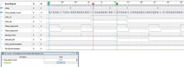
This test was successful with desired results as stated in the purpose of the test; the observation on the transmit-ter node from the Chipscope - shown in Figure 5 is as follows:
1. The default values of Phase Segment1 are 10 time quanta and Phase Segment2 is 5 time quanta, when the Delay Bus value is Zero.
2. The delay add signal on the VIO console is the syn-chronous input and when a user applies the input pulse it generates a delay as shown by the value of Delay bus signal at Marker T (As we set Delay=2 as a Trigger condition).
3. If we observe the value of Marker O for Time Quanta Count it is 11(Count starts from 0) which is 2 more than the Normal Phase segment1 value.
4. By adding this 2 time quanta delay before the dom-inant to recessive edge means this edge will have a positive phase error of 2 time quanta.
Figure 5: Chipscope Snapshot for Test Case A.
5. The Sampled bit signal represents the CAN Rx sig-nal at the sample point. This value for Recessive to Dominant edge happened on the Sample Point after MarkerO.
6. Resynchronization signal represents if any resynchro-nization happens in case of a +ive or -ive phase error on an edge. As this signal remained low hence prov-ing that no resynchronization happened.
All these steps verify the success of the test, this test case emphasis the usefulness of VIO core as a complex con-dition of introducing phase error to verify the behaviour of CAN Bit timing has been easily achieved without the use of any external input.
5.2
TEC non-increment on 13 bit long
Over-load Flag
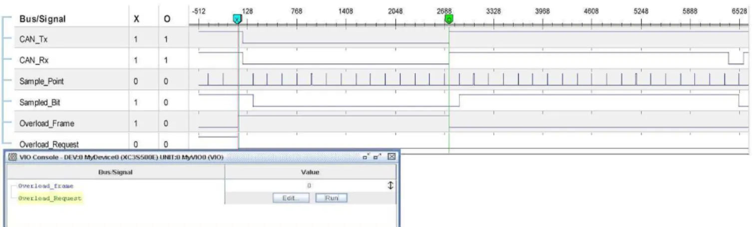
This test case is a part of error counter management class. The purpose of this test is to verify that an IUT acting as a transmitter when receives a 13 bit long overload flag shouldnt change the value of its transmit error counter (TEC). The test is setup using two in-stances of CAN Soft Core, one Soft core is acting as a IUT while the other soft core is used as LT to request an Overload frame and generate 13 dominant bits of overload flag. The Overload request is generated using a VIO synchronous input and then a 13 bit dominant value on the CAN Tx signal.
For this test case we will show snapshots at both LT Fig-ure 6 and the IUT node FigFig-ure 7. The system clock for this test case is 12 MHz. In Figure 6, we can see a VIO console with a synchronous input overload request, this signal request an overload frame (can only be requested by a receiver) between two data frames sent by a trans-mitter.
1. The signal Overload Request is also shown on the ILA screenshot, after which an Overload frame is sent after the Data frame is received successfully as can be seen as the Overload Frame signal is set high.
2. The Overload Frame lasts for 13 bit times as can be counted by the number of Sample points between Marker X (start of Overload Flag) and Marker O
(End of Overload Frame).
Now we will have a look on the IUT snapshot which is shown in Figure 7.
1. Before Marker O we can observe that a normal data frame is being transmitted as can be illustrated by different transmission states denoted by Trans-mit State xxxx.
2. At Marker O which is the end of Trans-mit State End of Frame we can observe a Over-load Frame signal demonstrating an OverOver-load Frame as we can see that the CAN Rx remains low between Marker T(Start of Overload Frame) to the Marker
O (End of Dominant Overload Flag).
3. The difference between MarkerOandX is 672, Each CAN bit time is given as 12Mhz/250Kbps= 48 clock cycles, while the difference of 672 illustrate 14 CAN bit time. T
4. he value of Transmit Error Counter was 6 before the completion of Data frame and changes to 5 af-ter a successful completion Data frame illustrated by Transmit State End Of Frame signal.
5. Even after receiving 13 dominant bits of Over-load Frame the Error Frame signal remains low and Transmit Error Counter doesn’t change.
Figure 6: Chipscope Snapshot at LT for Test Case B.
Figure 7: Chipscope Snapshot at IUT for Test Case B.
6. This concludes that the test is successful as the IUT has not considered a 13 bit dominant Overload Flag as an error. After Marker X we can see success-ful transmission of another frame i.e. at the end of Overload Frame. This is illustrated by several Trans-mit State signals.
The test cases to be described in Sections 5.3,5.4 illus-trate the use of the facility in showing conformance to another important aspect of CAN conformance testing; the behaviour of the protocol in abnormal (error) and overload conditions.
5.3
Elongated Error Flag
This test is a part of the Error Frame Management class in ISO 16845. The purpose of this test is to verify that a CAN transmitter will only tolerate 7 dominant bits after sending its own Error flag. The case described below is for when the Error Flag is elongated by 4 Dominant bits. This test involves two instances of the
IUT and the ARM7 Micro controller boards. The test should be setup as both the IUTs must be in default state ready for transmission or reception, an error bit is to be introduced on the CAN bus during an ongoing transmission. The transmitter after sensing the error -must send an error frame of 6 dominant bits due to its Active Error state. One of the receivers must send more than 7 dominant bits after receiving the Error flag. The transmitter must not take these extra dominant bits as an Error and shouldnt send any extra Error Frame, and should start to resent the corrupted message.
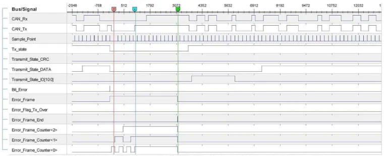
Figure 8: Chipscope Snapshot at Transmitter for Test Case C.
Chipscope snapshot shown in Figure 8 - are as follows:
1. On the Left of MarkerT, the TX State Xxxx high in-dicates an ongoing transmission. During data trans-mission a Bit Error is injected, indicated by the bit inversion as CAN Tx is recessive while CAN Rx is dominant (Bit inversion is done by the KE node).
2. The Error Frame exists between markers T and O
indicated by signal Error Frame, the Error Flag is between MarkerT andX. The end of Error Flag is indicated by a high Error Flag Tx Over signal. The Error Flag Counter bus is indicating the count of Er-ror Flag bits sent.
3. If we note at Marker X the CAN Tx signal has changed to Recessive but the CAN Rx signal remains Dominant for next 4 bits which is because of the su-perimposition of the Error Flag sent by the nodes on the CAN network.
4. The Error Frame is continued till MarkerO and the end is shown by a low Error Frame Signal and a high Error Frame End Signal.
5. On the right of Marker O we can clearly see that after three sample points (intermission Field) a new frame transmission has started in-dicated by Tx State, while Tx State ID[10:0] and Tx State Data indicating different states of trans-mission cycle.
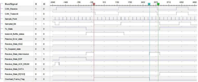
The observation at the receiver node (shown in Figure 9) is as follows:
1. Marker O indicates start of an Error Frame, the Tx State low indicating the node is a receiver.
2. The Error Flag Counter is a 4 bit wide bus which counts up to 11 bits i.e. it is sending 4 extra Domi-nant transmitter node. The DomiDomi-nant bits can also be verified by the CAN Tx and CAN Rx bits.
3. After the Error Flag Over Signal is set high the CAN Rx and CAN Tx signals turns to dominant for next seven bits indicating an Error frame Delimiter.
4. Right of Marker X the Error Frame signal is low and after three Recessive bits (Intermission Field) a new frame is started to be received (Tx State is low, CAN Tx is recessive), indicated by different Re-cieve State xxxx signals).
5.4
Overload Frame Management
Figure 9: Chipscope Snapshot at Receiver for Test Case C.
SOF and consider the dominant bit of the Intermission field as the SOF. Normal reception of the message should take place.
This test was successful with desired results as stated in the purpose of the test; the observation on the transmit-ter node from the Chipscope - shown in Figure 10 is as follows:
1. Left of MarkerT The Tx state flag is high indicat-ing ongoindicat-ing transmission, Receive State Data and ACK DELIM indicating a successful transmission while the node is error active.
2. At Marker T there is an error on the Re-ceive State Intermission field generating an overload frame with Overload Flag of six dominant and Over-load delimiter of 8 bits as can be seen by the count of sample point.
3. After the Overload frame an Intermission field signal can be seen at the MarkerX.
4. The third bit of intermission field is is a dominant bit as can be counted between MarkersX andO the number of sample points is 2 and the third sample point is a dominant bit.
5. Just after the Marker O we can see the Re-ceive State ID [10:0] going high without any SOF. The Identifier first 4 bits are dominant as required by the Test case.
6
COMPARATIVE STUDY
This Section presents a cost and flexibility comparison between conventional conformance test methods and our
proposed technique i.e. the use of hardware and software in an efficient manner to achieve the goal of testing a pro-tocol. The first observation is that the next facility does not require expensive and specialized PC interface cards such as [43, 44] which are normally required for CAN conformance testing [45]. These cards are used to cap-ture the Real-time bus data to analyse the internal status of different registers and to log the events; these cards not only required the hardware but also special software [46] along with interface cables which can also add to the cost and complexity of the setup. In our proposed implemen-tation we can analyse the internal state of CAN IUT or many of the other communication protocol directly using Chipscope. In addition, there are several key advantages of our proposed test bed using Chipscope over hardware logic analyser systems and pattern generators:
1. The standard bench analysers doesnt show enough signals as required in case of CAN or any other rele-vant protocols conformance as illustrated in section IV. There are Logic analyser systems which can show large number of signals simultaneously with large data widths [47, 48] but there prices are 10 times more than Integrated Logic analyser. The standard bench analysers can show Mega samples, while Chip-scope is limited to a Sample width of 16K, we can overcome this problem by using Digital clock Man-ager [42] which can divide or multiply the system clock by n times, the board we used in our system can divide the system clock by 16 times hence we were able to capture 16 times more sample than on system clock which can capture 3 to 4 complete CAN messages in a single trigger.
Figure 10: Chipscope Snapshot for Test Case D.
Chipscope can carry magnitude of these signals using a simple JTAG cable, although there are few solution like Agilents FPGA trace port citeTracePort which use a simple interface to analyse multiple signals but it also requires a specialized hardware and Chipscope pro tool.
3. Not only all I/O signals are accessible through Chip-scope but also internal wires can be traced [50] which are really helpful in Conformance testing specially when setting up triggering conditions we have lot more options to setup a trigger condition for exam-ple in test case A discussed it is really easy to setup a trigger condition to wait for an Overload Frame signal, while for external Logic analysers only I/O signals are available.
4. Virtual I/O is a real time tool for pattern generation, but doesn’t require any physical interface or port hence not only it save resources but also doesn’t have the physical impairments of an external signal. Also the ability to insert Virtual I/O cores into a design allows users to interactively verify the design much faster and easier, and the ability to define specific I/O can greatly reduce the time spent in verification.
7
Conclusions and Future Work
In this paper we have presented an approach to utilize Virtual I/Os and Integrated Logic Analysers to perform CAN conformance testing in accordance with the ISO standards. It has been shown that the facility is capable of performing the full range of test required and specially related to CAN bit timing tests conforming to the relevant CAN standard [21]. In conclusion, this facility can be assembled and used for a fraction of the cost of a
regular test facility for CAN conformance. A full list of the how each individual test may be implemented when using a facility such as this has been described in [20].
As a final note, it can be seen that test facility that has been described is not restricted to the CAN protocol, and with suitable modifications can be used to test confor-mance of many alternate network protocols, for example TTCAN [51].
References
[1] ISO/IEC. Information Technology- OSI - Confor-mance testing Methodology and frame work- Part 1: General concepts,ISO/IEC IS 9646-1,1994.
[2] Sheikh, I, Short, M. and Pont, M.J. “Hardware Im-plementation of a Shared Clock Protocol for CAN: A Pilot Study,”In proceedings of 4th UK Embedded Forum,, Southampton, UK. 9/2008
[3] Sheikh, I. and Short, M. “Improving information throughput in Controller Area Networks: Imple-menting the dual-speed approach,”In: Proceedings of the 8th International Workshop on Real-Time Networks (RTN09), Dublin, Ireland. 6/2009
[4] Mohor, I. Ethernet IP Core Design Document. Revision 0.4, Available at http://www.opencores.org/cvsweb.shtml/ethernet/ doc/eth design document.pdf.
[5] Raja, N. ”FPGA Implementation of a SIP message processor,” MSc Thesis, Computer Engineering De-partment, North Carolina University, 2006.
[6] Gmbh, R.B. ”E-Ray Flex Ray IP Module,” User manual, Revision 1.2.6, 2007.
[7] Bottoms, B. “The third millenniums test dilemma,”
IEEE Design & Test of Computers,”, V15, pp. 7-11, 10/98
[8] Lai, R. “A Survey of Communication protocol test-ing,” Journal of Systems and Software,”, V62, pp. 21-46, 2002
[9] Dutton, B.F. and Stroud, C.E. “Soft Core Em-bedded Processor Based Built-In Self-Test of FP-GAs,” In: Proceedings IEEE International Sympo-sium. on Defect and Fault Tolerance in VLSI Sys-tems, Chicago,Illinois, 10/2009
[10] IEEE 1802.3, Methodology and Implementation for AUI Cable Conformance Testing, Supplement to IEEE STD 802-1990.
[11] Conformance Test Methodology for Local and Metropolitan Area Networks: Supplement to Car-rier Sense Multiple Access with Collision Detection (CSMA/CD) Access Method and Physical Layer Specifications Type 10BASE-T Medium Attachment Unit (MAU) Conformance Test Methodology (Sec-tion 6).
[12] IEEE 802 Standard for Local and Metropolitan Area Networks: Overview and Architecture.
[13] Lawrenz, W. Kinowski, P. and Kircher, G. “CAN Conformance Testing-The Developing ISO Standard and Necessary Extensions,”In Proceedings of Inter-national Truck and Bus Meeting and Exposition,, In-dianapolis, Indiana, 11/98
[14] Lee, M.H. Kim, S.K. Park, M.S. Bae, Y.S. Chung, P. “IEEE 1284 softcore-implementation issues,”
ASICs, 1999. AP-ASIC ’99. The First IEEE Asia Pacific Conference on ,, pp 266-269, 99.
[15] IEEE standard for data delivery and logical channels for IEEE 1284 interfaces,IEEE Std 1284.4-2000, pp i-51, 2000.
[16] Sanyal, S. “Meeting Interoperability Requirements,”
XCELL Journal,Xilinx Inc, Fall 2004.
[17] Interoperability Lab, University of New Hampshire; http://iol.unh.edu
[18] “SignalTap II Embedded Logic analyser,” Altera; http://www.altera.com/products/software/pld/des-ign/verification/signaltap2/sig-index.html.
[19] “ChipScope Pro Serial I/O Tool Kit,” Xilinx; http://www.xilinx.com/ise/optional prod/cspro sio-kit.htm.
[20] Sheikh, I. and Short, M. “CAN Conformance Testing-A New approach,”tech-report ESL-09-01, ESL, Engineering Department, University of Leices-ter, 2/2009.
[21] R. Bosch, CAN Specification 2.0”, Postfach, Stuttgart, Germany: Robert Bosch GmbH, 1991.
[22] Short, M. and Pont, M.J. “Fault-Tolerant Time-Triggered Communication Using CAN,” IEEE Transactions on Industrial Informatics, V15, N2, 2007.
[23] Broster, I. and Burns, A. “Timely use of the CAN protocol in critical hard real-time systems with faults, ”In Proceedings of the 13th Euromicro Con-ference on Real-time Systems (ECRTS),Delft, The Netherlands, 06/2001.
[24] Pedreiras, P. and Almeida, L. “EDF message scheduling on controller area network,” Comput-ing and Control EngineerComput-ing Journal, pp. 163-170, 08/2002.
[25] Philips Semiconductor, SJA1000 Stand-alone CAN controller, Data Sheet, 01/2000.
[26] Microchip, MCP2515 Stand-alone CAN Controller with SPI Interface
[27] ISO, Road Vehicles- Controller Area Network (CAN) - Conformance Test Plan, DIS-16845, 2000.
[28] Kirschbaum, A. Renner, F.M. Wilmes, A. and Glesner, M. “Rapid-prototyping of a CAN-Bus con-troller: a case study,”In proceedings of Rapid System Prototyping, Seventh IEEE International Workshop on ,pp.146-151, 06/1996.
[29] Nimsub, K. Dawi, K. Kyuhyung, C. Jinsang, K. and Wonkyung, C. “Design and Verification of a CAN Controller for Custom ASIC,”CAN in Automation Proceedings of 10th iCC, 2005.
[30] Zarri, G. Colucci, F. Dupuis, F. Mariani, R. Pasquariello, M. Risaliti, G. and Tibaldi, C. “On the verification of automotive protocols,”In Proceedings of Design, Automation and Test in Europe, 2006,
pp.6-10. V2, 03/2006.
[31] Winter, A. Bittruf, D. Tanurhan, Y. and Muller-Glaser, K.D. “Rapid prototyping of a communica-tion controller for the CAN bus,”Rapid System Pro-totyping, 1996. Proceedings., Seventh IEEE Interna-tional Workshop on,pp.152-157, 06/1996.
[32] CAN 2.0 eVC, Yogitech SPA, 2005.
[33] Di Blasi, A. Colucci, F. and Mariani, R. “Y-CAN Platform: A Re-usable Platform for Design, Verifi-cation and Validation of CAN-Based Systems On a Chip,”ETS- 2003 Symposium,05/2003
[34] Ferreira, J. Oliveira, A. and Fonesca, J. “An Exper-iment to Assess Bit Error Rate in CAN,” In Pro-ceedings of 3rd International Workshop of Real-time Networks (RTN 04),Catania, Italy, 2004.
[35] Ayavoo, D. Pont, M.J. Short, M. and Parker, S. “Two novel shared-clock scheduling algorithms for use with CAN-based distributed systems,” Micro-processors and Microsystems,V31, N5, pp. 326-334, 2007.
[36] Sheikh, I. and Short, M. “A low-cost and flexible ap-proach to CAN conformance testing,”In Proceedings of the 6th International Conference on Informat-ics in Control, RobotInformat-ics and Automation (ICINCO 2009),Milan, Italy, pp. 97-104, 07/2009.
[37] Sheikh, I., Short, M. and Athaide, K.F. “Using Vir-tual I/O for CAN Bit Timing Conformance Tests,”
In Proceedings of the World Congress on Engineer-ing 2009,V1, pp. 480-485, London, UK, 07/2009.
[38] ISE Foundation, Xilinx Inc, 2008 ; http://www.xilinx.com/ise.
[39] uVision IDE Tool, Keil, 2008; http://www.keil.com/uvision.
[40] Tan, H. DeMara, R.F. Thakkar, A.J. Ejnioui, A. and Sattler, A.D. “Complexity and Performance Evalu-ation of Two Partial ReconfigurEvalu-ation Interfaces on FPGAs: a Case Study,”In Proceedings of the ERSA,
2006.
[41] Schieferdecker, I and Grabowski, J. “Conformance testing with TTCN,” Languages for Telecommuni-cations AppliTelecommuni-cations, V96, N4, pp. 8595, 2000.
[42] “Using Digital Clock Managers (DCMs) in Spartan-3 FPGAs, ”, XAPP462, Application Note, Xilinx Inc, 2003.
[43] “1 Port, High Speed CAN, USB Interface,”NI USB-8473, National Instruments, 2008.
[44] “CAN/CANopen Interface boards,” Softing AG, 2007; www.softing.com/home/en/pdf/ia/product-info/can-bus/D IA 41E 0711 CAN Interface Z.pdf.
[45] Lawrenz, W. Kinowski, P. and Kircher, G. “CAN Conformance Testing - State of the Art and Test Ex-perience,” In Proceedings of 5th International CAN Conference iCC98,San Jose, California, 11/1998.
[46] Lab VIEW, National Instruments, 2009; http://www.ni.com/labview86
[47] TLA 5000B Logic Analyzers, Tektronics, Inc, 2009; http://www.tek.com/products/logic analyzers/tla5-000
[48] 16900 Series Logic Analysis System Mainframes, Agilent Technologies, 2008; http://cp.literature.agilent.com/litweb/pdf/598904-21EN.pdf.
[49] Deep Storage with Xilinx Chipscope Pro and Agilent Technologies FPGA Trace Port Analyzer, Agilent Technologies, 2003; http://cp.literature.agilent.com/litweb/pdf/598873-52EN.pdf.
[50] Lee, T. Fan, Y. Yen, S Tsai, C. and Hsiao, R. “An Integrated Functional Verification Tool for FPGA Systems,”Second International Conference on Inno-vative Computing, Information and Control, ICICIC ’07,pp.203-203, 09/2007.
[51] Fuhrer,T. Mller, B. Dieterle, W. and Hartwich, F. “Time-triggered Communication on CAN (Time-triggered CAN TTCAN),”Proceedings of iCC 2000,
Amsterdam, The Netherlands, 2000.