Buckling analysis of laminated sandwich beam with soft core
Abstract
Stability analysis of laminated soft core sandwich beam has been studied by a C0 FE model developed by the authors
based on higher order zigzag theory (HOZT). The in-plane displacement variation is considered to be cubic for the face sheets and the core, while transverse displacement is quadratic within the core and constant in the faces beyond the core. The proposed model satisfies the condition of stress continuity at the layer interfaces and the zero stress condi-tion at the top and bottom of the beam for transverse shear. Numerical examples are presented to illustrate the accuracy of the present model.
Keywords
Sandwich beam; Soft core; Zigzag theory; Finite element; Stress continuity.
Anupam Chakrabarti∗a
, H.D. Chalaka, Mohd. Ashraf Iqbala and Abdul Hamid Sheikhb
a
Department of Civil Engineering, Indian Insti-tute of Technology Roorkee, Roorkee: 247667, India. Tel.: 1332-285844, Fax.: +91-1332-275568.
b
School of Civil, Environment and Mining En-gineering, University of Adelaide North Ter-race, Adelaide, SA 5005, Australia
Received 22 Mar 2012; In revised form 28 Apr 2012
∗Author email: [email protected]
1 INTRODUCTION
Laminated composite structures are widely used in aerospace, naval, civil, and mechanical industries due to its superior properties such as high strength/stiffness to weight ratio and greater resistance to environmental degradation over the conventional metallic materials. The use of high strength materials in such construction leads to slender sections, thus making buckling as a primary mode of failure of the member subjected to axial compressive forces. These buckling modes depend upon the material properties and relative stiffness of the face sheets and core.
The most important feature of the laminated composites (e.g., GFRP, CFRP etc.) is that these are weak in shear due to their low shear modulus compared to extensional rigidity. In order to fulfill the weight minimization, a laminated sandwich construction having low strength core and high strength face sheets may be used. As the material property variation is very large between the core and face layers in case of sandwich construction, the effect of shear deformation becomes more complex.
known as first-order shear deformation theory (FSDT). Based on the first-order shear defor-mation theory, Allen [5] presented a three-layered model for the analysis of sandwich beams and plates wherein the zigzag deformation pattern was considered. B-spline functions based on FSDT have been used by the Dawe and Wang [18, 19] as trial functions for Rayleigh-Ritz analyses and finite strip analyses. Aiello and Ombres [2] developed a model using FSDT to assess the optimal arrangement of hybrid laminated faces of sandwich panel for local buckling loads. Wang [49] employed the B-Spline Rayleigh-Ritz method based on first order shear de-formation theory to study the buckling problem of skew composite laminates. Sundersan et al. [46] have studied the influence of partial edge compression of composite plates by using a finite element method based on FSDT for analyzing isotropic plates. The structural behavior of sandwich laminated composites cannot be assessed satisfactorily by a FSDT, as the core and face sheets deform in different ways due to wide variation of their material properties, which is identified by a kink in the variation of in-plane displacements across the thickness at the interface between the core and stiff face layers. So as to predict the actual parabolic variation of shear stress, this (FSDT) required shear correction factor. This has inspired many researchers to develop a number of refined plate theories.
A higher order variation of in-plane displacement through the thickness is considered to represent the actual warping of the plate cross-section for overcoming the need of shear correc-tion factor so it is called as higher order shear deformacorrec-tion theory (HSDT). The warping of the cross section also allows higher order variation of transverse shear stresses/strains across the depth [38]. By choosing appropriate shape functions, four shear deformation theories presented by Aydogdu [10], are named as: parabolic shear deformation beam theory, hyperbolic shear deformation beam theory, first order shear deformation beam theory and exponential shear deformation beam theory, for the buckling analysis of composite beam. The theories developed for buckling analysis by Reddy and Phan [39], Kant and Kommineni [26], Khedir and Reddy [28] , Moita et.al [33, 34], Vuksanovic [48] and many other falls under this category. Song and Waas [44] presented a higher order theory for the buckling and vibration analysis of composite beams and the accuracy of HSDT was demonstrated compared to 1-D Euler-Bernoulli, 2-D clas-sical elasticity theory and Timoshenko beam theory. Frostig [23] obtained the general as well as local buckling loads for sandwich panels consisting of two faces and a soft orthotropic core using HSDT. Karama et.al [27] presented a multilayered laminated composite model by intro-ducing a sine function as a transverse shear stress function where a FE based software package Abaqus was used to check the efficiency of the model. Babu and Kant [11] presented two C0 isoparametric finite element formulations, one based on FSDT and other based on HSDT
Zhen and Wanji [51] presented global theories with higher order shear deformation and zigzag theories satisfying continuity of transverse shear stresses at interfaces for analyzing the global response of sandwich laminated beams. The effects of the number of higher order terms in the shear deformation as well as inter-laminar continuity of shear stress on global response of laminated beams and soft core sandwich beams were studied in this paper [51].
The actual behavior of a composite laminate is that the transverse strain may be discon-tinuous but the corresponding shear stress must be condiscon-tinuous at the layer interface [41], while HSDT shows discontinuity in the transverse shear stress distribution and continuity in the variations of the corresponding transverse shear strain across the thickness. This is mainly due to the different values of shear rigidity at the adjacent layers.
The above disparity leads to the development of layer-wise theories, which started with discrete layer theories. In discrete layer theories the unknown displacement components are taken at all the layer interfaces including top and bottom surfaces of the structure. Discrete layer theories proposed by Srinivas [45], Toledeno and Murakami [47], Robbins and Reddy [25] , Cetkovic [13] and many others assume unique displacement field in each layer and displacement continuity across the layers. In these theories, the number of unknowns increases directly with the increase in the number of layers due to which it required huge computational involvement. The improvement of layer-wise theories comes in the form of zigzag theories (ZZT), where the unknowns at different interfaces are defined in terms of those at the reference plane. The number of unknowns are made independent of the number of layers by introducing the transverse shear stress continuity condition at the layer interfaces of the laminate and the in plane displacements have piece-wise variation across the plate thickness in this theory (ZZT). Averill [6] developed a C0 finite element based on first order zigzag theory and overcome the
C1continuity requirement by incorporating the concepts of independent interpolations and
penalty functions. Hermitian functions were used by Di Sciuva [20, 21] to approximate the transverse displacement in the formulations. Carrera [22] used two different fields along the laminate thickness direction for displacement and transverse shear stress respectively for his formulation. Averill and Yip [7] developed a C0 finite element based on cubic zigzag theory,
using interdependent interpolations for transverse displacement and rotations and penalty function concepts.
In some improved version of these theories, the condition of zero transverse shear stresses at the plate/beam top and bottom was also satisfied. Kapuria et.al [40] developed 1D zigzag theory for the analysis of simply supported beams. The effect of the laminate layup and the thickness to span ratio was investigated. Zigzag models for laminated composite beams were developed by using trigonometric terms to represent the linear displacement field, transverse shear strains and stresses [42, 43]. However, the zigzag theory has a problem in its finite element implementation as it requires C1 continuity of the transverse displacement at the nodes.
To combine the benefits of the discrete layer wise and higher order zigzag theories, Cheung et.al [50], Yip and Averill [24], Icardi [8, 9] and many other authors developed theories which are known as sub-laminated models. Aitharaju and Averill [3] developed a new C0 FE based
strain field is also made field consistent. The transverse normal stress was assumed to be constant through the thickness of the laminate. The new FE was applied to model the beam as combination of different sub-laminates.
Ramtekekar et.al [36], Bambole and Desai [12] and many more developed a mixed FE approach for accurate analysis of stresses, where the stress components are assumed as the field variables at interface nodes along with displacement field variables. Dafedar et.al [17] and Dafedar and Desai [16] have presented a theory based on mixed higher order theory for the buckling analysis of laminated composite structures. Two sets of mixed models HYF1 and HYF2 have been presented by selectively incorporating non-linear components of Green’s strain tensor. Individual layer theory (ILT) based HYF1 and HYF2 models have been developed by considering a local Cartesian co-ordinate system at the mid-surface of each individual layer and at mid-surface of the entire structure respectively.
The transverse deformation is very significant in case of a laminated sandwich structure having a soft core as there is abrupt change in the values of transverse shear rigidity and thick-ness of face sheet and the core. As such to achieve sufficient accuracy, unknown transverse displacement fields across the depth in addition to that in the reference plane are essential to represent the variation of transverse deflection. This can be done by using sub-laminate plate theories but the number of unknowns will increase with the increase in the number of sub-laminates. On the other hand, introduction of additional unknowns in the transverse displacement fields invites additional C1 continuity requirements in its finite element
imple-mentation by using the zigzag theory as mentioned earlier. However, the application of a C1continuous finite element is not encouraged in a practical analysis.
Recently Pandit et.al [31, 32] proposed a higher order zigzag theory for the static and buckling analysis of sandwich plates with soft compressible core. In this model [31, 32] a nine-node isoparametric element with 11 field variables per nine-node was employed. To overcome the problem of C1continuity the authors [31, 32] have used separate shape functions to define the
derivatives of transverse displacements such C0finite element was used for the implementation
of the theory. It has imposed some constrains, which are enforced variationally through penalty approach. However, the problem of choosing suitable value for the penalty stiffness multiplier is a well known problem in the finite element method.
In this paper an attempt is made to do the stability analysis of laminated sandwich beam having soft compressible core based on higher order zigzag theory by using a C0 beam finite
element model recently developed by the authors [1]. The model satisfies the transverse shear stress continuity conditions at the layer interfaces and the conditions of zero transverse shear stress at the top and bottom of the beam. The isoparametric quadratic beam element has three nodes with seven displacement field variables (i.e., in-plane displacements and transverse displacements at the reference mid surface, at the top and at the bottom of the beam along with rotational field variable only at the reference mid surface) at each node. The displacement fields are chosen in such a manner that there is no need to impose any penalty stiffness in the formulation. The element may also be matched quite conveniently with other C0 elements.
having different geometry boundary conditions.
2 MATHEMATICAL FORMULATIONS
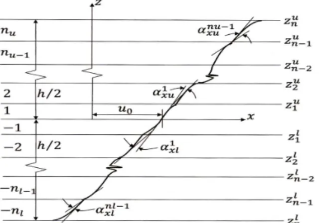
The in-plane displacement field (Figure 1) is chosen as follows:
U =u0+zθx+
nu−1
∑
i=1
(z−ziu)H(z−zui)αixu+
nl−1
∑
i=1
(z−zli)H(−z+zil)αixl+βxz 2
+ηxz 3
(1)
where,u0denotes the in-plane displacement of any point on the mid surface,θx is the rotation
of the normal to the middle plane about thez-axis,nu and nl are number of upper and lower
layers respectively,βx andθx are the higher order unknown, αixu and αixl are the slopes of i-th
layer corresponding to upper and lower layers respectively andH(z−zui)and H(−z+z l
i)are
the unit step functions.
Figure 1 General lamination scheme and displacement configuration.
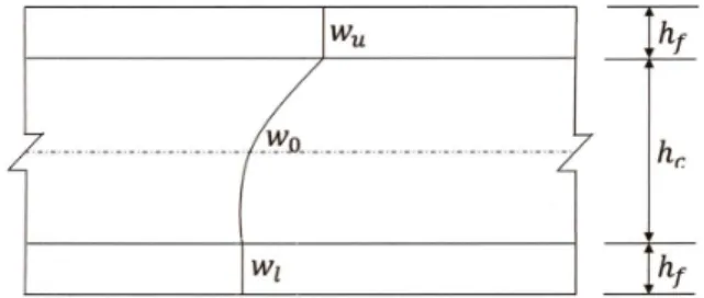
The transverse displacement is assumed to vary quadratically through the core thickness and constant over the face sheets (as shown in Fig. 2)and it may be expressed as,
W =l1wu+l2w0+l3wl f or core
=wu f or upper f ace layers
=wu f or lower f ace layers
(2)
where wu, w0 and wl are the values of the transverse displacement at the top layer, middle
layer and bottom layer of the core, respectively, and l1,l2 andl3 are Lagrangian interpolation
functions in the thickness co-ordinate.
Figure 2 Variation of transverse displacement (w) through the thickness of laminated sandwich beam. ⎧⎪⎪⎪ ⎨⎪⎪⎪ ⎩ σxx σzz σxz ⎫⎪⎪⎪ ⎬⎪⎪⎪ ⎭ = ⎡⎢ ⎢⎢ ⎢⎢ ⎣ ¯
Q11 Q¯12 0
¯
Q21 Q¯22 0
0 0 Q¯66
⎤⎥ ⎥⎥ ⎥⎥ ⎦ ⎧⎪⎪⎪ ⎨⎪⎪⎪ ⎩ εxx εzz εxz ⎫⎪⎪⎪ ⎬⎪⎪⎪ ⎭
...or{σ¯}=[Q¯K] {ε¯} (3)
where{σ¯},{ε¯}and [Q¯K]are the stress vector, the strain vector and the transformed rigidity
matrix ofk-th lamina, respectively.
Utilizing the conditions of zero transverse shear stress at the top and bottom surfaces of the beam and imposing the conditions of the transverse shear stress continuity at the interfaces between the layers along with the conditions,u=uuat the top andu=ul at the bottom of the
beam, βx,ηx,αixu,αixl, (∂wu/∂x)and (∂wl/∂x) may be expressed in terms of the displacement u0,θx,uu and ul as
B=[A]{α} (4)
where,
{B}={βxηxα 1
xuα
2
xu...α
nu−1
xu α
1
xlα
2
xl...α
nl−1
xl (∂wu/∂x) (∂wl/∂x)}
T
,{α}={u0θxuuul} T
and the elements of [A] are dependent on material properties. It is to be noted that last two entries of the vector{B} helps to define the derivatives of transverse displacement at the top and bottom faces of the beam in terms of the displacements u0, θx, uu, and ul to overcome
the problem of C1 continuity as mentioned before.
Using the above equations, the in-plane displacement field as given in equation (1) may be expressed as
U =b1u0+b2θx+b3uu+b4ul (5)
where, the coefficientsb′
isare function of thickness coordinates, unit step functions and material
properties.
The generalized displacement vector {δ} for the present beam model can now be written with the help of equations (2) and (5) as
Using strain-displacement relation and equations (1)-(4), the strain field may be expressed in terms of unknowns (for the structural deformation) as
{ε¯}={ε¯}L+{ε¯}N L
where,
The linear strain part is
{ε¯}L=[∂ U ∂ x
∂ W ∂ z
∂ U ∂ z +
∂ W
∂ x ]or{ε¯}L=[H] {ε} (6)
and non-linear strain part can be written as
{ε¯}N L={1/2(∂w¯/∂x)2+1/2(∂u¯/∂x)2}or{ε¯}N L=1/2[AG] {θ} (7)
where,
{θ}=[∂w¯/∂x ∂u¯/∂x]or{θ}=[HG] {ε}=[HG] [B] {δ} and
{ε}=[u0θxuuulwuw0wl(∂wu/∂x) (∂w0/∂x) (∂wl/∂x) (∂u0/∂x) (∂θx/∂x) (∂uu/∂x) (∂ul/∂x)]
and the elements of [H], [AG] and [HG] are functions of z and unit step functions. The values
of l1, l2,l3,bi’s and the elements of [H] are used as reported in the appendix (A,B and C) by
Chakrabarti et al. [1]. With the quantities found in the above equations, the total potential energy of the system under the action of transverse load may be expressed as
Πe=Us−Uext (8)
where Us is the strain energy and Uext is the energy due to the externally applied in-plane
load.
Using equations (3) and (6) , the strain energy (Us) is given by
Us=
1 2
n
∑
k=1
∫∫ {ε¯}T[Q¯k] {ε¯}dxdz=
1
2∫ {ε¯}
T
[D] {ε}dx (9)
where,
D=1 2
n
∑
k=1
∫ {H}T[Q¯k] {H}dz (10)
and the energy due to application of external in-plane load can be calculated as
Uext=
1 2
n
∑
k=1
∫∫ {ε¯}TN L[Si] {ε¯}N Ldxdz= 1 2∫ {ε¯}
T
N L[G] {ε¯}N Ldx (11)
where,
G= n
∑
k=1
∫ {HG} T
and the stress matrix[Si]may be expressed in terms of in-plane stress components of the i-th
layer as
[Si]=[ σx 0 0 0 ]
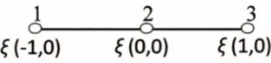
In the present problem, a three-node quadratic element with seven field variables (u0,w0,θx,uu, wu,ul and wl) per node is employed. Figure 3 shows the node numbering and natural
coordi-nate of the element.
Figure 3 Node numbering and natural co-ordinate of the beam element.
Using finite element method the generalized displacement vector δ at any point may be expressed as
{δ}= n
∑
i=1
Ni{δ}i (12)
where,δ=u0, w0, θx, uu, wu, ul, wl T
as defined earlier,δiis the displacement vector
correspond-ing to nodei,Niis the shape function associated with the nodei andn is the number of nodes
per element, which is three in the present study.
With the help of equation (12), the strain vector {ε} that appeared in equation (6) may be expressed in terms of field variables as
{ε}=[B] {δ} (13)
where is the strain-displacement matrix in the Cartesian coordinate system.
The elemental potential energy as given in equation (7) may be rewritten with the help of equations (8)-(13) as
Πe=1/2∫ {δ}T[B]T[D][B] {δ}dx−1/2∫ {δ}T[B]T[G][B] {δ}dx
=1/2{δ} T
[Ke] {δ}−1/2λ{δ} T
[KG] {δ}
(14)
where,
[Ke]=∫ [B]T[D][B]dx (15)
[KG]=∫ [B]T[G][B]dx (16)
where,[Ke]and[KG] are stiffness matrix and geometrical stiffness matrix.
The equilibrium equation can be obtained by minimizing Πe as given in equation (14) with
[Ke] {δ}=λ[KG] {δ} (17)
where λis a buckling load factor.
The displacements, stresses (in case of static analysis) and buckling loads in laminated sandwich beams are calculated by developing a numerical code to implement the above men-tioned operations involved in the proposed FE model. The skyline technique has been used to store the global stiffness matrix in a single array and Gaussian decomposition scheme is adopted for the static solution, while simultaneous iteration technique is used for solving the buckling equation (17).
3 NUMERICAL RESULTS
In this section, some examples on the buckling analysis of laminated sandwich beam having a soft core is analyzed by using the proposed FE model based on higher order zigzag theory. The accuracy and applicability of the proposed FE model based are demonstrated by solving a number of problems having different features. The results obtained are compared with the published results in some cases and finally many new results are also generated. The following different boundary conditions are used
1. Simply supported boundary condition (H): The field variables u0, w0, wu and wl are
restrained while θx, uuand ul are unrestrained in one boundary. In the other boundary,
the field variablesw0,wu and wl are restrained whileu0, θx, uuand ul are unrestrained.
2. Clamped boundary condition (C): All the nodal field variables at the boundary are fully restrained.
3. Free boundary condition (F): All the nodal field variables at the boundary are unre-strained.
The non-dimensional quantities used, to show different results are as follows
Buckling load,λ¯= λl 2
h2E T f
where h and l are depth and span length of the beam respectively andET f is the transverse
modulus of elasticity of face layer.
3.1 Three layered laminated composite beam (00
/900
/00)
For the convergence studies of critical buckling load, a three layer beam is analyzed taking mesh divisions 2, 5, 10, 16, 20 and 30. The layers are of equal thickness. The material properties [28]
Table 1 Material properties for laminated beams
Example Layer/Sheet Material properties
E1(psi) E3(psi) G12(psi) G13(psi) G23(psi) υ12 υ13 υ23
1 [28]# All 40.0E06 1.0E06 0.6E06 0.6E06 0.5E06 0.25 0.25 0.25
2 [30] All 25.0E06 1.0E06 0.5E06 0.5E06 0.6E06 0.25 0.25 0.25 3 [16] Face∗ 10.2E06 10.2E06 3.9E06 3.9E06 3.9E06 0.3 0.3 0.3
Core 1.5E-03 1.58E05 3.86E4 3.86E4 3.86E4 1E-05 3E-05 3E-05
4 [37] Face 19E6 1.5E6 1.0E6 0.9E6 1.0E6 0.22 0.22 0.49
Core 1.0E3 1.0E3 0.5E3 0.5E3 0.5E3 1E-5 1E-5 1E-5
∗Face number increases from the outer layers towards inside
# Reference for the material properties
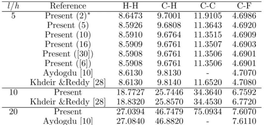
Table 2 Comparison of critical buckling load for laminated sandwich beam (00/900/00).
l/h Reference H-H C-H C-C C-F
5 Present (2)∗ 8.6473 9.7001 11.9105 4.6986
Present (5) 8.5926 9.6808 11.3643 4.6920 Present (10) 8.5910 9.6764 11.3515 4.6909 Present (16) 8.5909 9.6761 11.3507 4.6903 Present ([30]) 8.5908 9.6761 11.3506 4.6901 Present ([6]) 8.5908 9.6761 11.3506 4.6901
Aydogdu [10] 8.6130 9.8130 - 4.7070
Khdeir &Reddy [28] 8.6130 9.8140 11.6520 4.7080
10 Present 18.7727 25.7446 34.3640 6.7592
Khdeir &Reddy [28] 18.8320 25.8570 34.4530 6.7720
20 Present 27.0394 46.7479 75.0934 7.6070
Aydogdu [10] 27.0840 46.8820 - 7.6110
∗ Quantities within the parentheses indicate mesh size.
H-H: Hinged-Hinged; C-H: Clamed-Hinged;C-C: Clamped-Clamped and C-F: Clamped-Free
The beam is analyzed by considering four different boundary conditions and different values of thickness ratio(l/h). The results obtained by using the proposed FE model are presented in Table 2. It may be observed in Table 2 that the buckling loads are converged at mesh division 20. A mesh division 20 is taken for all subsequent analysis to get accurate results. The present results corresponding to arbitrary boundary conditions are compared with those published; FSDT [10] and TSDT [28]. It may be observed in Table 2 that the present results are in good agreement with the other results.
3.2 Multilayered composite beam (00/
900/
00 ....)
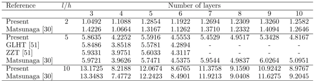
Table 1(Example 2). The critical buckling load has been calculated by considering different thickness ratios and varying the number of layers. The effect of bending-extension coupling may be seen from Table 3, which reduces the buckling load.
Table 3 Comparison of buckling stresses of multi-layered laminated beams.
Reference l/h Number of layers
3 4 5 6 7 8 9 10
Present 2 1.0492 1.1088 1.2854 1.1922 1.2694 1.2309 1.3260 1.2582
Matsunaga [30] 1.4226 1.0664 1.3167 1.1262 1.3710 1.2332 1.4094 1.2646
Present 5 5.8635 4.2252 5.5916 4.5553 5.4529 4.9517 5.3428 4.8167
GLHT [51] 5.8486 3.8518 5.5781 4.2894 - - -
-ZZT [51] 5.9331 3.9751 5.6033 4.3117 - - -
-Matsunaga [30] 5.9721 3.9626 5.7471 4.5375 5.9544 4.9837 6.0264 5.0951 Present 10 13.1725 8.2188 12.0674 8.6765 11.3758 9.1590 10.9242 8.9767 Matsunaga [30] 13.3483 7.4772 12.2423 8.4901 11.9213 9.0408 11.6275 9.2045
The results are shown in Table 3, along with the results reported in the literature based on global local higher order theory (GLHT) and ZZT [51] and GLHT [30]. It may be observed from Table 3 that the present results based on the higher order zigzag theory for the critical buckling load are on the lower side as compared to the other results based on ZZT [51] and GLHT [30], while it shows a good agreement with the results based on GLHT [51] .
3.3 Three layer soft core sandwich beam
A three layer simply supported sandwich beam is analyzed in this example using the present FE model. The ratio of the thickness of core to thickness of face sheets (tc/tf) is considered
to be 5, 25 and 50. The material properties [16] for the face sheets and core are given in Table 1 (Example 3). In Table 4, the non dimensional critical buckling load is reported for different thickness ratio(l/h). Results reported by Dafedar and Desai [16] based on higher order mixed formulation and the results reported by Zhen and Wanji [51] based on GLHT and ZZT along with the results obtained by using Abaqus (Ver.6.8) software package are considered for the comparison.
To model the laminated sandwich beam in Abaqus, 8000 eight node 3D shell elements (S8R) are used. From Table 5, it can be concluded that the present model performance is quite satisfactory as compared those presented by Zhen and Wanji [51] and Dafedar and Desai [16]. The present 1D results based on the refined theory are expected to be closer to the 3D analysis results. This is observed in Table 5 as the present results are quite close to the 3D analysis results obtained by using Abaqus.
3.4 Multilayered laminated soft-core sandwich beam
A multilayered laminated sandwich beam (00
/900
/00
/900
/C/900
/00
/900
/00
Table 4 Comparison of critical loads for three layered soft-core sandwich beam.
tc/tf l/h DD [16] Present GLHT [51] ZZT [51] Abaqus
5 2 0.006222 0.001540 0.006719 0.006794 0.001582
5 0.014320 0.010300 0.014840 0.014860 0.009765 10 0.041084 0.041830 0.041820 0.041820 0.036990 50 0.343190 0.364800 0.364800 0.364800 0.342700 25 2 0.001529 0.001532 0.001601 0.001601 0.001511 5 0.009031 0.009143 0.009142 0.009143 0.009019 10 0.031096 0.031685 0.03168 0.031680 0.031110 50 0.143850 0.155800 0.155800 0.155800 0.116800 50 2 0.001441 0.001510 0.001510 0.001510 0.001497 5 0.008555 0.008692 0.008692 0.008692 0.008614 10 0.026762 0.027565 0.027560 0.027560 0.026860 50 0.083230 0.090730 0.090720 0.090720 0.060720
ratio(l/h)ranging from 5 to 100 by considering the ratio of the thickness of core to thickness of face sheets as 25 for a simply supported boundary condition. To check the accuracy of present FE model to this new problem of multilayered sandwich beam, present results are compared with those obtained by using finite element software package Abaqus (Ver.6.8).
Table 5 Comparison of critical loads for multilayered soft-core sandwich beam.
tc/tf l/h Present Abaqus
25 5 0.00855 0.00843
10 0.03353 0.03299 50 0.49894 0.49398 100 0.80155 0.80085
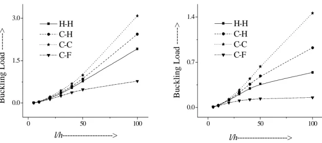
The variation of critical buckling load for different boundary conditions mainly; Hinge-Hinge(H−H), Clamped-Hinge(C−H), Clamped-Clamped(C−C)and Clamped-Free(C−F) over different thickness ratio(l/h) is shown in the Figure 4 (a−b). The ratio of thickness of core to thickness of the face sheets is considered to be 5 and 50 for the plot. The plot shows expected variation.
4 CONCLUSION
The stability behavior of laminated sandwich beam having a soft core is studied in this paper by using a C0 efficient finite element (FE) model developed by the authors. A refined higher
0 50 100 0.0 1.5 3.0 H-H C-H C-C C-F B u ck li n g L o ad - ---> l/h--->
0 50 100
0.0 0.7 1.4 B u c k li n g L o ad -
---> H-H
C-H C-C C-F
l/h--->
Figure 4 Variation of critical buckling load.
problems. The results obtained by using the present FE model are successfully compared with many published results and also with the results obtained by using FE based software package Abaqus. Many new results are also presented which should be useful for future research.
References
[1] A. Iqbal A. Chakrabarti, H.D. Chalak and A.H. Sheikh. A new fe model based on higher order zigzag theory for the analysis of laminated sandwich beam with soft core. Composite Structures, 93:271–279, 2011.
[2] M.A. Aiello and L. Ombres. Local buckling loads of sandwich panels made with laminated faces.Composite Structures, 38(1-4):191–201, 1997.
[3] V.R. Aitharaju and R.C. Averill. C0zigzag kinematic displacement models for the analysis of laminated composites.
Mechanics of Composite Materials & Structures, 6:31–56, 1999.
[4] S.S.J. Moy, A.K. Nayak and R.A. Shenoi. A higher order finite element theory for buckling and vibration analysis of initially stressed composite sandwich plates. Journal of Sound and Vibration, 286:763–780, 2005.
[5] H.G. Allen. Analysis and Design of Structural Sandwich Panels. Pergamon Press, London, 1969.
[6] R.C. Averill. Static and dynamic response of moderately thick laminated beams with damage. Composites Engi-neering, 4:381–395, 1994.
[7] R.C. Averill and Y.C. Yip. Development of simple, robust finite elements based on refined theories for thick laminated beams.Computers and Structures, 59:529–546, 1996.
[8] R.C. Averill and Y.C. Yip. Thick beam theory and finite element model with zigzag sub-laminate approximations. Journal of AIAA, 34:1627–1632, 1996.
[9] R.C. Averill and Y.C. Yip. Thick beam theory and finite element model with zigzag sub-laminate approximations. Journal of AIAA, 34:1627–1632, 1996.
[10] M. Aydogdu. Buckling analysis of cross-ply laminated beams with general boundary conditions by ritz method. Composite Science and Technology, 66:12484–1255, 2006.
[11] C.S. Babu and T. Kant. Two shear deformable finite element models for buckling analysis of skew fibre reinforced composite and sandwich panels. Composite Structures, 46:115–124, 1999.
[13] M. Cetkovic and D. Vuksanovic. Bending, free vibration and buckling of laminated composite and sandwich plates using a layerwise displacement model. Composite Structures, 88:219–227, 2009.
[14] A. Chakrabarti and A.H. Sheikh. Buckling of laminated composite plates by a new element based on higher order shear deformation theory. Mechanics of Advanced Materials and Structures, 10:303–317, 2003.
[15] A. Chakrabarti and A.H. Sheikh. Buckling of laminated sandwich plates subjected to partial edge compression. Int. J. of Mechanical Sciences, 47(418-436), 2005.
[16] J.B. Dafedar and Y.M. Desai. Stability of composite and sandwich struts by mixed formulation. Journal of Engi-neering Mechanics, 130(7):762–770, 2004.
[17] J.B. Dafedar, Y.M. Desai, and A.A. Mufti. Stability of sandwich plates by mixed, higher order analytical formulation. Int. J. of Solids and Structures, 40:4501–4517, 2003.
[18] D.J. Dawe and S.Wang. Spline finite strip analysis of the buckling and vibration of rectangular composite laminated plates. Int. J. Mech. Sci, 37(6):645–667, 1995.
[19] D.J. Dawe and S.Wang. Buckling and vibration analysis of composite plate and shell structures using the passas software package. Composite Structures, 38(1-4):541–551, 1997.
[20] M. DiSciuva. Development of anisotropic multilayered shear deformable rectangular plate element. Computers and Structures, 21:789–796, 1985.
[21] M. DiSciuva. A general quadrilateral multilayered plate element with continuous interlaminar stresses. Computers and Structures, 47:91–105, 1993.
[22] M. DiSciuva. C0 reissner-mindlin miltilayered plate element including zigzag and interlaminar stress continuity.
Journal of Numerical Methods in Engineering,, 39:1797–1820, 1996.
[23] Y. Frosting. Buckling of sandwich panels with a flexible core- higher order theory. Int.J. Solids Structures, 35(3-4):183–204, 1998.
[24] U. Icardi. Applications of zigzag theories to sandwich beams. Mechanics of Advanced Materials and Structures, 10:77–97, 2003.
[25] D.H. Robbins Jr. and J.N. Reddy. Theories and computational models for composite laminates. Allied Mechanics Rev, 49:155–199, 1996.
[26] T. Kant and J.R. Kommineni. C0 finite element geometrically non-linear analysis of fiber reinforced composite and
sandwich laminates based on a higher order theory.Computers and Structures, 45(3):511–520, 1992.
[27] M. Karama, B.A. Harb, S. Mistou, and S. Caperaa. Bending, buckling and free vibration of laminated composite with a transverse shear stress continuity model.Composites part B, 29:223–234, 1998.
[28] A.A. Khdeir and J.N. Reddy. Buckling of cross ply laminated beams with arbitrary boundary conditions.Composite Structures, 37(1):1–3, 1997.
[29] H. Matsunaga. Buckling instabilities of thick elastic beams subjected to axial stresses. Computers and Structures, 59(5):859–868, 1996.
[30] H. Matsunaga. Vibration and buckling of multilayered composite beams according to higher order deformation theories.Journal of Sound and Vibration, 246(1):47–62, 2001.
[31] M.K. Pandit, A.H. Sheikh, and B.N. Singh. Buckling of laminated sandwich plates with soft core based on an improved higher order zigzag theory.Thin-Walled Structures, 46:1183–1191, 2008.
[32] M.K. Pandit, A.H. Sheikh, and B.N. Singh. An improved higher order zigzag theory for the static analysis of laminated sandwich plate with soft-core. Finite Element in Analysis and Design, 44(7):602–610, 2008.
[33] J.S. Moita, C.M.M. Soares, and C.A.M. Soares. Buckling behavior of laminated composite structures using a discrete higher order displacement model. Composite Structures, 35:75–92, 1996.
[34] J.S. Moita, C.M.M. Soares, and C.A.M. Soares. Buckling and dynamic behavior of laminated composite structures using a discrete higher order displacement model. Computers and Structures, 73:407–423, 1999.
[36] G.S. Ramtekkar and Y.M. Desai. Natural vibrations of laminated composite beams by using mixed finite element modeling. Journal of Sound and Vibration, 257(4):635–651, 2002.
[37] M.K. Rao, K. Scherbatiuk, Y.M. Desai, and A.H. Shah. Natural vibrations of laminated and sandwich plates.J Eng Mech, 130:1268–78, 2004.
[38] J.N. Reddy. A simple higher order theory for laminated composite plates.Journal of Applied Mechanics, 51:745–752, 1984.
[39] J.N. Reddy and N.D. Phan. Stability and vibration of isotropic, orthotropic and laminated plates according to a higher order shear deformation theory. Journal of Sound and Vibration, 98(2):157–170, 1985.
[40] S. Kapuria, P.C. Dumir, and N.K. Jain. Assessment of zigzag theory for static loading, buckling, free and force response of composite and sandwich beams. Computers and Structures, 64:317–327, 2004.
[41] A.H. Sheikh and A. Chakrabarti. A new plate bending element based on higher order shear deformation theory for the analysis of composite plates.Finite Element in Analysis and Design, 39:883–903, 2003.
[42] R.P. Shimpi and Y.M. Ghugal. A new layerwise trigonometric shear deformation theory for two layered cross-ply beams.Composite Science and Technology, 61:1271–1283, 2001.
[43] R.P. Shimpi and Y.M. Ghugal. A new layerwise trigonometric shear deformation theory for two layered cross-ply beams.Composite Science and Technology, 61:1271–1283, 2001.
[44] S.J. Song and A.M. Waas. Effects of shear deformation on buckling and free vibration of laminated composite beams. Composite Structures, 37(1):33–43, 1997.
[45] S. Srinivas. A refined analysis of composite laminates. Journal of Sound and Vibration, 30:495–507, 1973.
[46] P. Sundaresan, G. Singh, and G.V. Rao. Buckling of moderately thick rectangular composite plates subjected to partial edge compression.Int. J. Mech. Sci, 40(11):1105–1117, 1998.
[47] A. Toledano and H. Murakami. Composite plate theory for arbitrary laminate configuration. Journal of Applied Mechanics, 54:181–189, 1987.
[48] D. Vuksanovic. Linear analysis of laminated composite plates using layer higher order discrete models. Composite Structures, 48:205–211, 2000.
[49] S. Wang. Buckling analysis of skew fibre-reinforced composite laminates based on first-order shear deformation plate theory. Composite Structures, 37(1):5–19, 1997.
[50] Y.K. Cheung, L.G. Tham, and K.P. Chong. Buckling of sandwich plate by finite layer method. Computers and Structures, 15(2):131–134, 1982.
![Table 4 Comparison of critical loads for three layered soft-core sandwich beam. t c /t f l/h DD [16] Present GLHT [51] ZZT [51] Abaqus 5 2 0.006222 0.001540 0.006719 0.006794 0.001582 5 0.014320 0.010300 0.014840 0.014860 0.009765 10 0.041084 0.041830 0.04](https://thumb-eu.123doks.com/thumbv2/123dok_br/18884598.423522/12.892.234.712.145.368/table-comparison-critical-loads-layered-sandwich-present-abaqus.webp)