DOI : 10.5121/ijsea.2015.6402 11
Yousef Abuseta and Khaled Swesi
Computer Science Department, Faculty of Science
Al-Jabal Al-Gharbi University, Libya
ABSTRACT
Self adaptation has been proposed to overcome the complexity of today's software systems which results from the uncertainty issue. Aspects of uncertainty include changing systems goals, changing resource availability and dynamic operating conditions. Feedback control loops have been recognized as vital elements for engineering self-adaptive systems. However, despite their importance, there is still a lack of systematic way of the design of the interactions between the different components comprising one particular feedback control loop as well as the interactions between components from different control loops . Most existing approaches are either domain specific or too abstract to be useful. In addition, the issue of multiple control loops is often neglected and consequently self adaptive systems are often designed around a single loop. In this paper we propose a set of design patterns for modeling and designing self adaptive software systems based on MAPE-K. Control loop of IBM architecture blueprint which takes into account the multiple control loops issue. A case study is presented to illustrate the applicability of the proposed design patterns.
KEYWORDS
Self-adaptive, feedback control loop, Design Patterns
1.
INTRODUCTION
The development of today's software systems has become a very difficult task to accomplish. This is due to the dynamic and heterogeneous nature of these systems. It is rather difficult to build a software system that meets all requirements and make it survive without the need for a change either in response to new user requirements or to changing environmental conditions. Furthermore, many of these systems cannot afford too long downtime while the source code is being modified. Traditional top-down engineering approaches are insufficient to handle the complexity and evolution problems inherent in decentralized, continually evolving software [
19
]. Therefore, there is an increasing need for the software systems to be able to self adapt to accommodate new requirements not foreseen at design time or in response to changes on contextual conditions.12 requires shifting the human role from operational to strategic. Humans define high level policies that state how a system should react to changes and the system then carries out corrective changes (adaptations) autonomously at run-time [6].
Research in self-adaptive systems have been conducted within the different areas of software engineering, including requirements engineering [2], software architecture [
9
,10
,25
], middleware [18], and component-based development [23
].Feedback control loops [
20
] from the control theory area have been identified as vital elements in engineering self-adaptive software systems. Such control loops are typically organized by means of four components that are responsible for the fundamental functions of self-adaptation: Monitor, Analyze, Plan, and Execute, often referred to as the MAPE loop as in the IBM architecture blueprint [13
]. In [7
] these functions are referred to as collect, analyze, decide, and act.Despite the importance of feedback loops regarding the introduction of self adaptability to today's software systems, there is still a lack of systematic way of the design of the interactions between the different components comprising one particular feedback control loop. Existing approaches are either too specific for some domains or highly abstract to be useful in modeling a wide range of domains. Also, little attention has been given to modeling and designing multiple interacting control loops since most approaches assume the existence of only one single control loop and design their self adaptive systems accordingly. In addition, the responsibilities of each component in the feedback control loop are not defined properly and consequently each SAS designer tends to define them differently. The monitor responsibility, for instance, is often defined in a way that overlaps with the analyzer's where the monitor accomplishes the data collection, aggregation and reasoning tasks. This contradicts with the separation of concerns design principle. Such a design principle contributes to a clean and flexible design of software systems in general and self adaptive systems in particular.
In this paper we introduce a set of design patterns which serves as an assisting tool for software designers of self adaptive systems. Such patterns support reuse of known solutions and evaluated ideas and architectures taken from well designed and accepted approaches for the area of self adaptive systems engineering. Our design patterns are based on the feedback control loop proposed by the IBM architecture blueprint [
13
].13
2. BACKGROUND
2.1 Feedback Control Loop
Feedback loops provide the generic mechanism for self-adaptation [3]. A feedback loop is a control loop where the output of the controlled system is fedback to the input. It allows therefore to adjust operations according to differences between the actual output and the desired output. In other words, feedback control loops are entities that observe the system and initiate adaption. A feedback loop typically involves four key activities: collect, analyze, decide, and act [7]. Sensors collect data from the running system and its environment which represents its current state. The collected data are then aggregated and saved for future reference to construct a model of past and current states. The data are then analyzed to infer trends and identify symptoms. The planning activity then takes place and attempts to predict the future and prepare change plan to act on the running system through a set of effectors or actuators [3].
2.2 Managed and Managing Systems
Self adaptation capabilities can be introduced to the software system either internally or externally [
26
]. In the internal approach, the adaptation logic (managing system) is intertwined with the core application (managed system) which may take the form of the exception handling. In this case, the adaptation engine is system dependent and thus difficult to maintain, evolve, and reuse. In contrast, in the external approach, the concerns of the adaptation logic are separated from the core application. Most of the existing approaches adopt the external approach since it enables the realization of some important software qualities such as the reusability and modifiability. The IBM architecture blueprint [13
] is an example of this approach which is shown in Fig.1. As depicted in Fig.1, the managing system consists of four main activities: monitor, analyze, plan and execute. These activities share a knowledge base component which contains information about the system state as well as the policy engine that controls the system functioning. A set of sensors is used to collect the important data to the adaptation process and send them to the monitor for further processing while a set of effectors is used to apply the corrective changes stated in the plan.14
2.3 Design Patterns
A Software design pattern is a repeatable solution to a usually occurring problem in software designs. It is a template for how to solve a problem that can be used in many different situations [
8
]. Design patterns [8
,17
] have fundamentally changed the way we approach the design of large software systems. Applying design patterns not only helps system designers take advantage of the software community’s collective experience as captured in the patterns, it also enables others studying the system in question to gain a deeper understanding of how the system is structured, and why it behaves in particular ways.In [
8
], design patterns have been classified into three categories as follows:• Creational patterns which are concerned with creating the appropriate objects for a given case. This gives more flexibility to the program since choosing the right object to create is postponed to the runtime.
• Structural patterns which are concerned with composing groups of objects into larger structures.
• Behavioral patterns which define the communication between a set of objects in a software system and how the flow is controlled in such a system.
A number of design patterns belonging to the categories listed above plays a crucial role in designing self adaptive systems. The observer design pattern, for instance, can fit nicely when establishing the relationship between the monitor component and the sensor. Also, the Strategy design pattern can be used to design and implement the plan component which contains a set of possible actions executed when some particular conditions hold. Sometimes it is desirable and beneficial for the self adaptive systems to offer the option of reverting to previous system states (prior to the application of the plan changes). In the latter, the command design pattern comes in play and offers this feature. It is similar to the system restore option offered by Windows where the system might encounter some problems and choosing a restore point might solve the issue.
3. RELATED WORK
15 Weyns [14] propose ActiveFORMS, short for Active Formal Models, which contributes to the self adaptive systems with an approach that guarantees the verified adaptation behavior at design time and provides support for dealing with dynamic goals at runtime. Ben Said et al [1] proposed a set of design patterns targeting the real time systems. Iglesia [15] in his PhD thesis proposed and modeled the semantics for a set of MAPE-K formal templates for the design of self adaptive systems. In [27], a set of design patterns is introduced by the authors to model the various interactions between MAPE loops in decentralized control of self adaptive software systems.
4. PROPOSED DESIGN PATTERNS
Our proposed design patterns are built on some previous works carried out for addressing the development of self adaptive software systems. In particular, we use the concepts proposed by IBM architecture blueprint [13] for modeling the feedback control loops, namely the Monitor, Analyze, Plan, and Execute. We also take advantage of the work presented in [3, 6] in which the design space of self adaptive systems is presented as a set of dimensions whereas each dimension is defined by a design question. We also studied the design patterns introduced in [27] to model the various interactions between multiple MAPE loops of self adaptive software systems.
4.1 Metamodel of self adaptive systems
16 Fig. 2. Metamodel of MAPE-K based Self Adaptive Systems
4.2 SAS Design Patterns
Below, we introduce the five design patterns: SAS Monitor, SAS Analyzer, SAS Plan, SAS Execute and SAS Knowledge. Each design pattern proposed here is partially complied with the Gamma [8] template structure. Each pattern is described by six fields, namely the pattern name, intent, context, motivation, structural view and participants. UML diagrams are used here to depict the structural and behavioural views of the design patterns.
SAS Monitor design pattern
PatternName: SAS Monitor.
Intent: to establish the relationships between the components participating in accomplishing the
monitoring activity of self adaptive systems using the MAPE control loop.
Context: this pattern is used in the first stage of the feedback control loop process aiming at
introducing self adaptability to software systems. In this stage, what properties to monitor
question is answered.
Motivation: the detection of a property threshold violation represents the trigger of the adaptation
process in self adaptive systems. Therefore, in order to accomplish the detection process, a monitor component must be introduced.
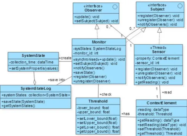
Structural view: the components involved in the monitoring activity as well as their relationships
17 one- to- many relationship. There is a concurrency taking place here since the sensors keep running simultaneously and notifying the monitor of any change occurred to the properties of their direct responsibility. To handle concurrency, most modern programming languages such as Java offer the multithreading technique where a number of threads are executing apparently at the same time. Therefore, the sensor class in Fig.3 is stereotyped with the word "Thread". Also since this concurrency leads to many threads attempting to access the same program (the monitor object), a synchronization mechanism should be put in place. This is realized in Java by preceding the operation in question (the update operation of monitor class) by the keyword
synchronized.
Fig. 3. UML Class diagram for the monitoring activity components.
Participants: lists the classes involved in the pattern and describes each class's responsibilities.
Sensor Its sole responsibility is to collect data about the system property of high interest to the
18
System property Also referred to as the context element, this is the property that is of a direct
connection and great interest to the adaptation process. This property is the target of the monitoring activity and the main concern of the monitor component is to keep its value within a desirable or acceptable range. Often, a threshold is used to accomplish this task. Examples of system properties include server load, server throughput, response time and bandwidth usage. The system property contributes to the runtime system state.
Environment property the environment is defined as any external actor that affects the
system in some way. Therefore, the environment property represents any contextual information that is external to the system in question and contributes to its runtime state. Examples of such properties include the time of operating, the current client connections in client-server architecture, etc.
Threshold this is the value that the monitor component will compare against to decide whether
the current value of the system property is still within a desirable or acceptable range. A threshold might have two values for the lower and upper bounds. An example of a threshold would be if server CPU load becomes greater than 50%, or if load changes by more than 20%.
System runtime state At runtime, the system state is represented by the combination of the
values of system properties and the properties representing the environment or the context within which the system is operating. Each system has a desirable state driven by its goals and non functional requirements. Often the deviation from this desirable state is the trigger of the adaptation process.
Monitor. It is responsible for collecting data from a set of sensors, filtering and aggregating this
data and sending it to the analyzer component for any possible symptoms of system goals violation. The combined data collected from the sensors represent and form the system (or subsystem) runtime state. Conceptually, the monitor plays the role of the master in the master-slave relationship while the sensors play the master-slave roles. However, in terms of software design patterns, the observer pattern is used here where the monitor plays the observer role while the subject role is played by the sensor(s).
Behavioral view. The behavioral view depicts the interactions between the different components
19 Fig. 4. The behavioral view of the monitoring activity of MAPE-K
SAS Analyzer design pattern
Pattern Name: SAS Analyzer.
Intent: to establish the relationships between the components participating in accomplishing the
analyzer activity of self adaptive systems using the MAPE control loop.
Context: this pattern is used in the stage of evaluating the collected data by the monitor
component for any possible symptoms of system goals and requirements violation. In this stage, the question of whether an adaptation is required or not is answered.
Motivation: detection of a system property (or system state violation) threshold violation
represents the trigger of the adaptation process in self adaptive systems. Therefore, in order to accomplish the detection process, an analysis activity must be carried out which is performed here by the SAS analyzer pattern.
Structural view: the components involved in the analyzer activity of self adaptive systems as well
20 Fig. 5. UML Class diagram for the Analysis activity components
Participants: lists the classes involved in the pattern and describes each class's responsibilities.
Analyzer. Its responsibility is to receive collected and logged data (from monitor) representing
the system (or subsystem) state history and analyze them for any possible symptoms of system goals and requirements violation. The analyzer notifies the plan of any necessary adaptations via sending an adaptation request.
Symptom. Represents one of the undesirable states that the system in question must detect and
take corrective actions against. A highly loaded server is an example of such symptoms. Symptoms work with a set of combined conditions and when these conditions are satisfied, the analyzer raises an adaptation request signal and sends it, along with the necessary information, to the plan component.
AdaptationRequest. Once the analyzer analyses the received data from the monitor and decides
that some symptoms exist, an adaptation request is created and sent to the plan component along with the necessary information. The latter include the event describing the symptom (e.g. highly loaded server) and the occurrence of this event in a specified time window (e.g. last two hours).
SymptomRepository. It contains a set of predefined symptoms that the system in question
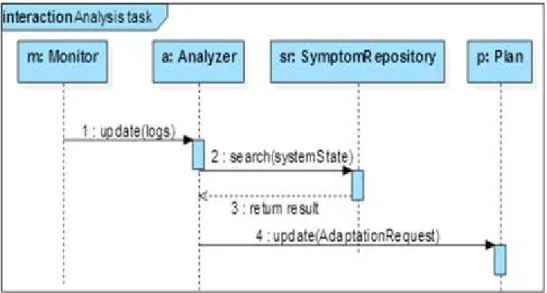
21
Behavioral view: The behavioral view depicts the interactions between the different components
involved in the analysis activity using UML Sequence diagram as shown in Fig. 6. Notice that both the analyzer and plan components have the update operation, which is part of the Observer interface, since they both play the observer role in this interaction. The analyzer receives the collected data from the monitor (the trigger of the analysis activity) and the plan receives the adaptation request signal from the analyzer once a symptom of undesirable system state is detected.
Fig. 6. The behavioral view of analysis activity of MAPE-K
SAS Planner design pattern
Pattern Name SAS Plan.
Intent: establish the relationships between the components participating in accomplishing the
plan activity of self adaptive systems using the MAPE-K control loop.
Context: this pattern is used in the stage of constructing the change plan which is composed of a
set of corrective actions in response to an adaptation signal raised by the analyzer component. In this stage the questions of what actions to be taken and in what order.
Motivation: When modeling a self-adaptive systems, designers need to specify the adaptation
strategy to use to calculate the adaptation decisions.
Structural view: the components, and their relationships, involved in the plan activity of self
22 Fig. 7. UML Class diagram for the Planning activity components
Participants lists the classes involved in the pattern and describes each class's responsibilities as
follows:
Plan is responsible for constructing the change plan in response to an adaptation request received from the analyzer. The plan component uses the policy engine for accomplishing its task and then sends the constructed change plan to the execute component to dispatch these changes. The plan is linked with the analyzer and execute using the observer design pattern where it takes on both the observer and subject roles respectively and thus implements the Observer and Subject interfaces.
PolicyEngine It contains the policies (high level goals) that control the operating and
functioning of the system in question. Policies take the form of Event-Condition-Action (ECA) rules which determine the actions to be taken when an event is raised provided some specific conditions are met. A general form of a policy rule can be written as:
on eventif condition do action.
The policy engine belongs to the knowledge base of the feedback control loop. It provides the necessary interface for the system administrators to define and modify the policies of the system at hand.
ChangePlan. It contains the actions that should be dispatched to the execute component in order
23
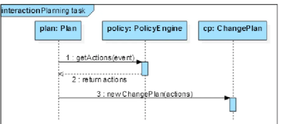
Behavioral view: The behavioral view depicts the interactions between the different components
involved in the planning activity using UML Sequence diagram as shown in Fig.8.
Fig. 8.The behavioral view of planning activity of MAPE-K
SAS Execute design pattern
Pattern Name: SAS Execute.
Intent: to establish the relationships between the components participating in accomplishing the
execute activity of self adaptive systems using the MAPE control loop.
Context: this pattern is used in the stage of executing the adaptation actions or change plan that is
received from the plan component. These actions must be executed in some specific order (sequentially or concurrently or maybe mixed of the two) as stated in the plan. The execute component uses a set of actuators or effectors to apply the required changes to the system and usually involve setting new values to the system properties which are collectively constitute the system state. In this stage, what properties to change question is answered.
Motivation: this pattern models and design the last activity of the MAPE-K which involves
dispatching some corrective actions to a number of effectors in order to bring the system back to a desirable or acceptable state. Executing the adaptation in the order stated in the change plan is crucial for a successful transition from an undesirable to desirable state.
Structural view: the components and their relationships are described using UML class diagrams
as shown in Fig.9. The central class of this activity is the executor which contains the update operation where it receives the change plan (corrective actions) from the plan. Once it has received the corrective actions, it dispatch them to a set of effectors to apply the changes to the target system and environment properties (referred to as context element in Fig. 9). Therefore, it is linked with the plan and effector components using the Observer design pattern where it plays both the observer role ( with the plan) and the subject role (with the effector) and thus has to implement two interfaces, namely the observer and the subject.
Participants: lists the classes involved in the pattern and describes each class's responsibilities.
Executor. It is responsible for sending the corrective actions to one or more effectors in a
specific order.
Effector. It is responsible for applying changes to system or environment properties according to
24 Fig. 9. UML Class diagram for the Execute activity components
Behavioral view: the behavioral view depicts the interactions between the different components
involved in the execute activity using UML Sequence diagram as shown in Fig.10.
25
5. E
VALUATION
C
ASE
S
TUDY
We evaluate the effectiveness of our devised design patterns in introducing self adaptation to an existing systems in two aspects: (1) How easy to introduce the self adaptation capability to a software system? (2) How flexible are the design patterns in accommodating the different scenarios of feedback control loop interactions?. To carry out the evaluation , we introduce here the case study of augmenting Virtual Learning Environments (VLE), such as Moodle and Blackboard, with self adaptive capabilities. Architecturally, these environments are viewed and designed using the client-server style where such environments provide E-learning services through a set of servers (server farm) which can be accessed by a number of learners as well as instructors (clients). One of the major concern of these environments is to achieve scalability (scale up/down) to either accommodate more clients accessing the system or to cut down the operating cost by switching off some servers. When managing a client-server based software system, the load balancing technique largely contributes to solving many server related problems including the response time, throughput and scalability. Therefore, the feedback control loop is necessarily composed of components concerned with the load balancing mechanism. Such components include load monitor, load analyzer, load balancing planner and load balancing executor. A knowledge base component is used here by these components to achieve their tasks. The candidate properties that can be identified here for monitoring along with the components that they may apply to are as follows:
• load and throughput properties which are associated with the server component. Load expresses how many processes are waiting in the queue to access the server processor or can be measured by the CPU usage while throughput measures the amount of messages that a server processes during a specific time interval.
• latency property is associated with the client component since latency is measured from the client machine which is the time taken from sending a request to receiving a reply. • cost property is associated with the Server component (number of active servers).
The adaptation process is triggered by the outcome of the observation of the server load. The possible adaptations, which depend on the current system state and on the system goals, are as follows:
• Add server: this operation causes the addition of a new server to the server farm as a
corrective action to the sever high load provided that this wouldn't affect the operating cost.
• Remove server: this operation causes the removal of a server from the server farm either
because of a low load at specific time or as a response to an unresponsive server.
26
unresponsive. The high load event is raised when a server load becomes greater than 70% (upper
bound threshold) while the very low load event is detected when the load is less than 5% (lower bound threshold) for some specific period (last two hours for instance). The unresponsive event is raised when no new reading of server load is received from the sensor for some specific period. The plan then constructs the corrective actions based on the system policies.
The two main policies of this system are:(1) add new server when a high load event is raised provided that the new number of active servers does not exceed the defined threshold (5 for example) , and (2) remove server from the system when either the very low load or unresponsive
event is raised.
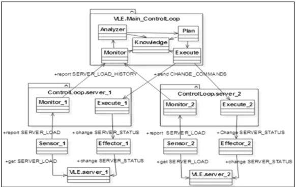
So far, we have demonstrated how to map the concepts presented in our design patterns to concepts in a real world example. To illustrate the flexibility of accommodating the different scenarios of feedback control loop interactions, we construct the possible organisation (shown in Fig. 11) of the self adaptive system which is tailored for this case study. A number of interactions can be recognized in Fig. 11. A monitor to monitor and execute to execute are two examples of an interaction where the two components are of the same type. We were able to model this kind of the interactions because we have designed the monitor and execute components (the same applies to the analyzer and plan) as both an observer and subject according to the Observer design pattern. In the register operation of the Subject interface, for example, the required parameter is of Observer type, therefore a monitor can register with another monitor to be notified of possible changes. Here, each monitor is responsible for collecting the server load of its subsystem (e.g. VLE.server_1 ) from the sensor and then report it to the monitor in the main control loop whose responsibility is to aggregate the collected data from the monitors and send it to the analyzer. Scalability (up/down) can be easily accomplished here since whenever we add/remove server to or from the server farm, we register or unregister the main monitor with or from the monitor of the recently added or removed server.
27
6. CONCLUSIONS
In this paper, we have introduced a set of design patterns to model the four main activities of the MAPE-K control loop which are used to engineer self-adaptive systems (SAS). Accordingly, such patterns are termed as SAS Monitor, SAS Analyzer, SAS Plan and SAS Execute. Also, the interactions between the different MAPE-K components are modeled and designed. Such interactions include Sensor-Monitor, Monitor-Analyzer, Analyzer-Plan, Plan-Execute and Execute-Effector. We have applied the Observer design pattern for each interaction where all components (except for the sensor and effector) play both the observer and subject roles and thus implement two interfaces namely the observer and subject. This, besides the stated above interactions, enables the establishment of the interaction between two component of the same type (monitor for instance) which is needed in some situations. The E-learning system case study was used to illustrate the applicability of part of these design patterns. As future work and suggested research, the following issues need to be addressed:
• A more detailed case study to illustrate the application of our proposed deign patterns.
• The application of our design patterns to introduce the self adaptation capability to VLEs at the core services level. Such services include a self adaptive user interface and self adaptive learning paths. In the case study presented here, we were interested in providing the scalability at the hardware level (server farm). The server farm represents the platform where theVLEs are executed.
• Modeling and programming the different states that each MAPE component goes through during the management of the managed system.
• A complete lifecycle for the development of self adaptive systems.
• The impact of the architectural style of the system under development on the feedback control loops organization (decentralized for instance).
R
EFERENCES[1] M. Ben Said, Y. Kacem, M. Kerboeuf, N. Ben Amor, M. Abid. "Design patterns for self-adaptive RTE systems specification". International Journal of Reconfigurable Computing, Vol. 2014 (2014). [2] G. Brown, B. Cheng, H. Goldsby and J. Zhang. "Goal-oriented specification of adaptation
requirements engineering in adaptive systems". In: ACM 2006 International Workshop on Self-Adaptation and Self-Managing Systems (SEAMS 2006), Shanghai, China, pp. 23–29 (2006).
[3] Y. Brun at el."Engineering Self-Adaptive System through Feedback Loops,” in Software Engineering for Self Adaptive Systems", Springer-Verlag Berlin Heidelberg 2009, Cheng B. et al. (Eds), pp 48-70, 2009.
[4] F. Buschmann et al, Pattern-Oriented Software Architecture: System of Patterns, John Wiley, 1996. [5] J. Camara, R. de Lemos, N. Laranjeiro, R. Ventura, M. Vieira. "Testing the robustness of controllers
for self-adaptive systems". Journal of the Brazilian Computer Society 2014.
[6] R. de Lemos et al., " Software Engineering for Self-Adaptive Systems: A Second Research Roadmap, Springer-Verlag Berlin Heidelberg 2013 (Eds.): Self-Adaptive Systems, LNCS 7475, pp. 1–32, 2013. [7] S. Dobson et al. "A survey of autonomic communications". ACM Transactions Autonomous
Adaptive Systems (TAAS) 1(2), 223–259 (2006).
[8] E. Gamma, R. Helm, R. Johnson, and J. Vlissides. Design Patterns: Elements of Reusable Object-Oriented Software. Addison-Wesley Professional, 1995.
28 [10] D. Garlan, S. Cheng and B. Schmerl."Increasing system dependability through architecture-based
self-repair". In: de Lemos, R., Gacek, C., Romanovsky, A. (eds.) Architecting Dependable Systems. LNCS, vol. 2677. Springer, Heidelberg (2003).
[11] D. Garlan, B. Schmerl, and S. Cheng, " Software Architecture-Based Self-Adaptation", Springer Science+Business Media, LLC 2009.
[12] H. Gomma and M. Hussien, "Software Reconfiguration Patterns for Dynamic Evolution of Software Architectures", IEEE Conference on Software Architecture (WICSA’04), 2004.
[13] IBM. "An architectural blueprint for autonomic computing. IBM", 2005.
[14] M. Iftikar and D. Weyns. "ActivFORMS: Active Formal Models for Self-Adaptation". The 9th International Symposium on Software Engineering for Adaptive and Self-Managing Systems 2014 [15] D. Iglesia, A Formal Approach for Designing Distributed Self-Adaptive Systems, PhD Thesis, 2014. [16] B. Jacob, R. Lanyon-Hogg, D. Nadgir and A. Yassin. "A Practical Guide to the IBM Autonomic
Computing Toolkit". IBM 2004.
[17] R. Johnson. "Components, frameworks, patterns". In Symposium on Software Reusability, 1997. [18] J. Kramer and J. Magee."The Evolving Philosophers Problem: Dynamic Change Management", IEEE
Transactions on Softwr Eng, Vol. 16, No. 11, Nov 1990.
[19] H. Liu and M. Parashar. "Accord: a programming framework for autonomic applications". IEEE Transactions on Systems, Man, and Cybernetics 36(3), 341–352 (2006).
[20] H. Muller, M. Pezze and M. Shaw. "Visibility of control in adaptive systems". In: Proceedings of Second International Workshop on Ultra-Large-Scale Software- Intensive Systems (ULSSIS 2008), pp. 23–27. ACM/IEEE (2008) .
[21] L. Northrop, P. Feiler, R. P. Gabriel, and et al. Ultra-Large-Scale systems - the software challenge of the future. Technical report, Software Engineering Institute, Carnegie Mellon, June 2006.
[22] P. Oreizy, M. M. Gorlick, R. N. Taylor et al., “An architecture-based approach to self-adaptive software”. IEEE Intelligent Systems and Their Applications, vol. 14, no. 3, pp. 54–62, 1999.
[23] C. Peper and D. Schneider."Component engineering for adaptive ad-hoc systems". In: ACM 2008 International Workshop on Software Engineering for Adaptive and Self-Managing Systems (SEAMS 2008), Leipzig, Germany, pp. 49–56 (2008)
[24] A. J. Ramirez and B. H. C. Cheng, “Design patterns for developing dynamically adaptive systems,” in Proceedings of the ICSE Workshop on Software Engineering for Adaptive and Self-Managing Systems (SEAMS '10), pp. 49–58, ACM, USA, 2010.
[25] U. Richter, M. Mnif, J. Branke, C. Muller-Schloer and H. Schmeck. "Towards a generic observer/controller architecture for organic computing". In: Hochberger, C., Liskowsky, R. (eds.) INFORMATIK 2006: Informatik f¨ur Menschen. GI-Edition – Lecture Notes in Informatics, vol. P-93, pp. 112–119 (2006).
[26] M. Salehie and L. Tahvildari, “Self-adaptive software: landscape and research challenges,” ACM Transactions on Autonomous and Adaptive Systems, vol. 4, no. 2, article 14, 2009.
[27] D. Weyns et al. "On patterns for decentralized control in self-adaptive systems". In R. de Lemos, H. Giese, H. A. Muller, and M. Shaw, editors, ¨ Software Engineering for Self-Adaptive Systems, volume 7475 of Lecture Notes in Computer Science, pages 76–107. Springer, 2012.
AUTHORS
Yousef Abuseta received an M.Sc in Computer Engineering in 2003 from University of Hertfordshire, UK. In 2009, he received a PhD degree in Software Engineering (Autonomic systems) from Liverpool John Moores University, UK. He has been lecturing at Al-Jabal Al-Gharbi University since 2011 where he is working as a Senior Lecturer. His research interests include self adaptive systems, autonomic systems, design patterns, E-learning, Model Driven Development (MDD) and Service Oriented Architecture (SOA).
Khaled Swesi received an M.Sc in Computer Science in 2003 from Newcastle University, UK. In 2010, he received a PhD degree in Software Engineering from De Montfort University, UK. He joined Al-Jabal Al-Gharbi University in 2012 where he is working as a Senior Lecturer. His research interests include E-learning, AI and web-based
![Fig. 1. Autonomic computing control loop [16]](https://thumb-eu.123doks.com/thumbv2/123dok_br/17298392.248473/3.918.293.617.765.978/fig-autonomic-computing-control-loop.webp)