Abstract
A novel Normal and Shear Deformation Theory (NSDT) for anal-ysis of laminated composite and sandwich beams, taking into account shear deformation as well as normal deformation, is de-veloped. The paper investigates flexural behaviors of thick lami-nated and sandwich beams under plane stress conditions using NSDT. A generalized displacement-based refined formulation is elucidated with inclusion of various warping functions in terms of thickness coordinates to represent shear and normal deformation effects. These effects become pronounced in thick laminated beams and particularly in sandwich beams with transversely flexible core. Present formulation satisfies the shear stress free surface condi-tions at the top and bottom surfaces of the beam with realistic through-the-thickness variation of transverse shear stresses. The results obtained are compared with higher order theories available in literature. It is observed that NSDT predicts displacement and stresses accurately compared to other higher order theories.
K eywords: Shear deformation, transverse flexibility, laminated thick beam, sandwich beam, transverse shear stress.
Stress Analysis of Laminated Composite
and Sandwich Beams using a Novel Shear
and Normal Deformation Theory
1 INTRODUCTION
Laminated composite structures are used in many engineering applications such as aerospace,
au-tomotive, and marine engineering. Laminated composites have high strength to weight ratio making
it ideal for such applications. In early 18th century Euler and Bernoulli presented Elementary Beam
Theory (EBT), which disregard the effect of shear deformation and consequently under predicts
deflections and over predicts natural frequencies and buckling load. This results in an inaccurate
local as well as global response of the structures. Many efforts have been carried out since last few
decades to accurately assess the response of laminated composites.
Eshwar G. Pawar a Sauvik Banerjeeb YogeshM. Desai c
Department of Civil Engineering, Indian Institute of Technology Bombay, Powai, Mumbai, India.
a (Corresponding Author)
Research Scholar
E-mail: [email protected] b Associate Professor
E-mail: [email protected] c Professor
E-mail:[email protected]
http://dx.doi.org/10.1590/1679-78251470
Latin A m erican Journal of Solids and Structures 12 (2015) 1340-1361
Timoshenko (1921) pioneered development of kinematics by allowing linear shear deformation in
thickness direction of beams together with rotatary inertia. However, due to kinematics of
defor-mation of the theory, the transverse shear strain is constant through-the-thickness, violating shear
stress free surface conditions. Shear correction factor needs to be employed for appropriate
represen-tation of strain energy of deformation. It depends on material and geometric properties as well as
loading and boundary conditions. Shear correction factor can be eliminated by using proper higher
order theories so as to satisfy shear stress free boundaries. Lo
et.al.
(1977) proposed the expansion
of displacement functions in terms of various powers of thickness coordinates. Using this approach,
Levinson (1981), Bickford (1982) Khdier and Reddy (1997) presented third order theories for
beams. A new class of theories higher than third order was formulated by Kant and Manjunath
(1989), Manjunath and Kant (1993). Equivalent single layer, displacement based, strain consistent
higher-order shear deformation theory for analysis of symmetric and unsymmetric laminated beams
has been used by Zenkour (1999).
To improve the accuracy of the transverse stress prediction, layer-wise higher-order theories
based on assumed displacements for individual layers, have been developed and used by Shimpi and
Ghugal (1999), Carerra
et.al.
(2013), Frostig
et.al.
(1992), Kapuria
et.al.
(2004). Layerwise theories
are layer dependent and the number of degrees of freedom involved is very high and hence these
theories computationally complicated.
Bambole and Desai (2007) have formulated hybrid interface finite element for laminated
compo-site and sandwich beams. Each lamina is modeled using hybrid interface element at at the top and
bottom lamina interfaces. Desai and Ramtekkar (2002) developed a two dimensional (2D) mixed
finite element (FE) model through the thickness of a laminate under the plane stress condition of
elasticity using principle of minimum potential energy. Continuity of transverse stresses and
dis-placement fields has been enforced through the thickness direction. Recently, Kant
et.al.
(2007)
proposed semi-analytical method for analysis employing transformation of boundary-value problem
to a set of initial value problems.
The classical theories assume that the cross-section normal to the neutral axis remain plane after
deformation. It leads to gross error in predicting displacements and stresses in thick beams and
laminated composites and become significantly pronounced in case of sandwich beams with
trans-versely flexible core; especially in vicinity of singular conditions like supports and concentrated
loads.
Latin A m erican Journal of Solids and Structures 12 (2015) 1340-1361
Figure 1: Deformation of sandwich beam (a) stiff core and (b) soft core, under localized loads.
In the present work, a novel, generalized Normal and Shear Deformation Theory (NSDT) is
devel-oped for incorporating shear deformations as well as normal deformations. The present theory is
based on variational principles and consistent formulations are derived accordingly.The
mathemati-cal formulation and the solution with appropriate boundary conditions are discussed in the next
section. Further, numerical examples are presented for validation and efficacy of the present theory.
2 THEORETICAL FORMULATION
The theoretical formulation of a shear deformation theory for beam based on certain kinematical
and physical assumptions is presented. The principle of virtual work is used to obtain the governing
differential equations and the associated boundary Conditions.
The theoretical formulation of the normal and shear deformation theory (NSDT) for laminated
composite and sandwich beams founded on kinematic and physical mechanism with consistent
mathematical basis, is presented.
The beam under consideration occupies the region given as:
0 x L; b 2 y b 2;and
2 2
h z h
. Domain of the beam and typical laminate configuration is shown in Figure 2.
Figure 2: Beam in plane stress condition subjected to transverse loading and its geometry.
w
ftw
fb= w
ftw
ftw
fb ≠ wftx
z
h
L
,
;
z
,
w x z
x z
,
;
xz
,
u x z
x z
q x
z h
b
y (1)
(2)
(k)
(N)
zk z1
Latin A m erican Journal of Solids and Structures 12 (2015) 1340-1361
2.2 Selection of Kinematics
It is a prerequisite to select a kinematics such that it should satisfy stress-free boundary conditions
at the top and bottom of the beam. It is apparent that higher order terms with thickness coordinate
needs to be an odd function for pertinent representation of transverse shear stresses
through-the-thickness of the beam; such that,
z
z
f
f
h
h
and
z
z
f
f
h
h
(1)
Selection of even functions in higher order terms leads to shear traction along the top and bottom
surfaces of the beams, violating the conditions of stress-free boundaries.
The generalized displacement field for the present NSDT is given as,
0 x z
U
= u
0z w , +
12
,
zh
x z
x
f
h f
x
(2)
W
= w
0 12
,
zh
x z
x
f
f
x
(3)
Rewriting,
0 x
U
x z,= u
0 xz w , +
x(4)
0
,
x z
x
x
W
= w
(5)
where,
U
is the inplane displacement components in x direction, and
W
is the transverse
displace-ment in the
z
direction. As stated in the foregoing discussion, the function can be selected as any
appropriate odd function. Specific warping functions used in the present study are enlisted
in Table 1.
In case of the present NSDT, it is noteworthy that coefficient of
xis a derivative of
coeffi-cients of shear slopes and its inclusion leads to non-trivial solution of traction-free boundaries.
2.3 Warping Functions
Accuracy of a refined theory depends on the selection of the warping function incorporated in the
kinematics of the theory. Foremost attempt to include warping function is made by Reissner (1975)
with a cubic form. Panc (1975) discussed this theory comprehensively in his monogram on theories
of elastic plates. Ambartusmian (1958) presented a different variant of cubic function to represent
warping. Levinson (1980) and Murthy (1981) proposed a simplified parabolic warping functions;
with later developments by Reddy (1984). Arbind
et.al.
(2014) developed modified couple
stress-based third-order theory for nonlinear analysis of functionally graded beam. Touratier (1991)
em-ployed trigonometric functions; whereas Soldatos (1992) used hyperbolic functions and Karama
et.al.
(2003) used exponential functions to characterize warping of cross-section.
(
(
(
(
(
(
(
(
(
(
(
(
(
(
(
(
(
)
)
)
)
)
)
)
)
)
)
)
)
)
)
)
)
Latin A m erican Journal of Solids and Structures 12 (2015) 1340-1361
Albeit several attempts are made to incorporate the warping function, these theories do not
con-sider normal deformability in formulations; which is significant especially in sandwich beams with
transversely flexible cores. This paper presents a novel theory which in its generalized form includes
warping of cross sections together with normal deformability.
Model
Warping Functions
z h z h
NSDT-1
cosh
12sinh
z hh
z 1
2
cosh
cosh
zh
NSDT-2 z 2 h2 4 z2 3 h2 8 z2 2
NSDT-3 5z 4 1 4z2 3h2 5 4 1 4z2 h2
NSDT-4 z 1 4z2 3h2 1 4z2 3h2
NSDT-5
h
sin
z h
cos
z h
NSDT-6 2z h2
z e
2 2
2 2 3 4
4
z h z h
e
e
z
h
Table 1: List of warping functions used in the present NSDT.
Normal and shear strains are obtained within the framework of linear theory of elasticity using the
displacement field given by Eq. (5) and (6). These relationships are given as follows:
,
x Ux
,
z W,z,
xy yz 0,
zx U,z W,x(6)
Each lamina in the laminate is in a state of plane stress. The constitutive relation for a typical kth
lamina is thus written simply as,
k k k
ij
C
ij ijor,
11 13 13 33 66 0 0 0 0k k k
x z xz xz C C C C C x z
(7)
where stiffness coefficients
Cijare,
1 13 3 3 11 13 33
13 31
, ,
, ,
1
E E E
C C C
,
C
66G
13(8)
Latin A m erican Journal of Solids and Structures 12 (2015) 1340-1361
2.4 Governing Equations and Boundary Conditions
Using the expressions for strains and stresses from equation (6) and (7) in the principle of virtual
work, variationally consistent governing differential equations and boundary conditions for the
beam under consideration can be obtained. The principle of virtual work when applied to the beam
is given as,
0 0
1
0
k k
n x L x L
k k k
zx
z x z x
k
b z = zk+ 1 x x z z zx dx dz z = zk+ 1 q W dx dz
z= δ + δ + δ z= =
(9)
where, symbol denotes the variational operator. Employing Green's theorem in equation (9)
suc-cessively, we obtain the coupled Euler-Lagrange equations, which are the governing differential
equations of the beam and the associated boundary conditions of the beam. The governing
differen-tial equations obtained are as follows:
0 11 0, 11 0, 11 , 13 ,
0 11 0, 11 0, 11 , 13 ,
11 0, 11 0, 11 , 66 66 13 ,
13 0, 13 0, 13 66 , 66 , 33
: 0
:
: 0
: 0
xx xxx xx x
xxx xxxx xxx xx
xx xxx xx x
x xx x xx
u A u B w E A
w B u D w F B q x
E u F w H A A D
A
u
Bw
D A A A(10)
The associated boundary conditions obtained are as below:
At the ends of beam i.e.
x 0and
x a11 0, 11 0, 11 , 13 0
11 0, 11 0, 11 , 13 , 0
11 0, 11 0, 11 , 13 0,
11 0, 11 0, 11 , 13
0 or is prescribed 0 or is prescribed 0 or is prescribed 0 or is
x xx x
xx xxx xx x
x xx x x
x xx x
A B E A
B D F B
B D F B
E F H D
u
w
u
u
w
w
u
w
w
u
w
56 56 ,
prescribed 0 or is prescribed
x
A A
(11)
Thus, the variationally consistent governing differential equations and boundary conditions are
ob-tained.
Solution of the set of partial differential equations can be found by converting PDE to
simulta-neous algebraic equations. The solution should satisfy governing differential equation at every point
of the domain for specified boundary and initial conditions of the system. Such a solution can either
in form of closed-form or infinite series. Closed-form solutions (CFS) are expressed in terms of finite
number of terms.
F”ll”wi“– Navier s s”luti”“ pr”cedure, CFS s t” t—e displaceme“t variables a“d l”adi“– term
satisfying boundary conditions can be expressed in following forms,
0 0
1
, , cos
m m
m
u u x
,
0 01
, , , , sin
m m m
m
w q w q x
(12)
where
m Land
,
m m
0 0 m m
u , w ,
are coefficients, which can be evaluated after substituting
in the set of four governing differential equations and solving the resulting simultaneous equations.
C”“verti“– PDE s t” simulta“e”us al–ebraic equati”“s, by substituti“– CFS s,
we get,
K u qLatin A m erican Journal of Solids and Structures 12 (2015) 1340-1361
The elements of stiffness matrix are given as follows,
2 4 2 2
11 11 22 11 33 66 11 44 33 66
3 2 3
12 11 13 11 14 13 23 11
2
24 13 34 66 13
; ; ;
; ; ;
; and ij ji
K A K D K A H K A A
K B K E K A K F
K B K A D K K
(13)
3 ILLUSTRATIVE EXAMPLES
A computer program incorporating the present methodology has been developed in FORTRAN 90
for analysis of homogeneous, layered beams simply supported on both ends. In order to prove the
efficacy of the present theory, various numerical examples have been performed. Results have been
compared with elasticity solution wherever available in literature.
Illustrative examples covering simply supported, symmetric and unsymmetric cross-ply
laminat-ed, sandwich beams subjected to transverse loading have been considered for highlighting the
sali-ent features of the pressali-ent theory. Material properties for the examples are tabulated in Table 2.
Example Set Source Elastic Properties
1 MAT-1 − E = 1.0, ν = 0.3
2,3,5 MAT-2 Pagano (1969) E1 = 172.4 GPa, E2 = 6.89 GPa, E3 = E2 G12 = G13 = 3.45 GPa, G23 = 1.378 GPa ν12 = ν13 = ν23 = 0.25
4 MAT-3 Kapuria et.al. (2007) E1 = 131.0 GPa, E2 = 10.3 GPa, E3 = E2
G12 = G13 = 7.17 GPa, G23 = 2.87 GPa ν12 = ν13 =0.25, ν23 = 0.33
6 MAT-4 Pagano (1969) Face sheet MAT-2 Core Material
E1 = E2 = 0.276 GPa, E3 = 3.45 GPa G12 = 0.1104 GPa, G23 = G13 = 0.414 GPa, ν12 = ν13 = ν23 = 0.25
7 MAT-5 Noor and Burton (1994) Kapuria et.al.(2004)
Face sheet
E1 = 131.1 GPa, E2 = 6.9 GPa, E3 = E2 G12 = 3.588 GPa, G13 = 2.3322 GPa,
G23 = 3.088 GPa, ν12 = ν13 = 0.32, ν23 = 0.49 Core Material
E1 = 0.2208 MPa, E2 =0.2001 MPa E3 = 0.2760 MPa, G12 = 16.56 MPa G23 =455.4 MPa, G13 = 545.1 MPa ν12 =0.99, ν13 = ν23 = 0.00003
Table 2: Material properties.
(
(
(
)
)
Latin A m erican Journal of Solids and Structures 12 (2015) 1340-1361
Normal in-plane stress has no reference to the surface boundary conditions; therefore, it can be
di-rectly obtained from constitutive relations. However, with the use of constitutive relations for
de-termination of transverse stresses, the stress boundary conditions on the top and the bottom
sur-faces of laminated beams are satisfied and interlaminar continuity is not satisfied. This drawback
can be overcome by imposing equilibrium equations of elastic continua to evaluate transverse shear
and transverse normal stresses. In tensorial notations, it is given as,
( ), 0
k
ij j
for
i, j x, y.Results reported in the present work are expressed in normalized form for consistent comparison
as follows,
, 2 2 0 L h x xb
q
,
2,0
L Z
z z
b
q
,
zx 0 zx 0,Zb
q
,
2 0, 0 Zb E
u
u
q h
,
3 2 , 4 2 0
100
L zb h E
w
w
q L
(14)
Beam bending is a case of plane stress analysis and is more pertinent when the beam is narrow;
whereas cylindrical bending is a plane strain problem, which is a direct reduction of three
dimen-sional solutions to a two-dimendimen-sional solution (Pagano (1969)).
Solution to plane strain analysis is sought by considering one of the plane of plate as infinite.
Some researchers have compared beam bending results with cylindrical bending of long plate, may
be due to paucity of appropriate examples. However, it is opinion of the authors that, since the
theoretical foundation of plane stress and plane strain is different, it is imprecise to compare these
results; albeit the results of two classes are close.
In order to prove effectiveness of the present theory, numerical investigations have been
ca-rried out for following examples with different materials and configurations.
Example 1.
Homogeneous isotropic beam with material set MAT-1 (Table 3).
Example 2.
Homogeneous orthotropic beam with material set MAT-2 (Table 4).
Example 3.
Unsymmetric cross-ply laminated beam (0
o/90
o) with material set MAT-2 (Table 5).
Example 4.
Unsymmetric cross-ply laminated beam (0
o/90
o/0
o/90
o) with MAT-3 (Table 6).
Example 5.
Three-layered symmetric cross ply laminated beam (0
o/90
o/0
o) with MAT-2 (Table 7).
Example 6.
Three-layered symmetric sandwich beam (0
o/core/0
o) with MAT-4. (Table 8).
Example 7.
Three-layered sandwich beam with graphite epoxy faces and soft core with MAT-5 and
thickness as (0.1h/0.8h/0.1h) (Table 9).
The beam is subjected to transverse load,
q x
( )
on surface
z h 2acting in the z direction as
de-fined in equation (13). For single sinusoidal load,
q
mq
0and
m 1. Whereas, for uniformly
dis-tributed load this coefficient is given as,
4 0 for 1, 3, 5,...0 for 2, 4, 6,...
m
q m m
Latin A m erican Journal of Solids and Structures 12 (2015) 1340-1361
The illustrated examples are initially analyzed for single sinusoidal load for validation and later
all these examples are reanalyzed considering uniform load. The results of converged Fourier series
are tabulated.
Figure 3: Typical sinusoidal and uniform loading on a layered beam.
4 DISCUSSIONS
Exact elasticity solutions for the laminated beams are not available in literature to the best of
au-t—”rs ’“”wled–e. Pa–a“”
(1969) has provided solution for long plates under cylindrical bending. As
mentioned previously, even though the results of cylindrical bending and beam bending are close,
these are altogether different problems. Therefore, semi-analytical solutions given by Kant
et.al.
(2007) are used for comparison with available examples. Their methodology involves
transfor-mation of boundary-value problem to a set of initial value problems and requires higher
computa-tional cost.
hc
h h
Z
X
1
( ) sinm x m a m
q x q
hc
h
Z
h
X
0
( )
sin
axLatin A m erican Journal of Solids and Structures 12 (2015) 1340-1361 S Theory
Sinusoidal Load Uniform Load
TOP
x xBOT xzmax w xTOP xBOT xzmax w
4
NSDT-1 −0.6232 0.6232 0.4745 14.1088 −0.7646 0.7646 0.6902 17.8367 NSDT-2 −0.6700 0.6700 0.4743 14.1089 −0.8251 0.8251 0.7166 17.8366 NSDT-3 −0.6719 0.6719 0.4743 14.1089 −0.8276 0.8276 0.7166 17.8366 NSDT-4 −0.6241 0.6241 0.4766 14.1089 −0.7658 0.7658 0.6898 17.8366 NSDT-5 −0.6334 0.6334 0.4911 14.0910 −0.7775 0.7775 0.6690 17.8145 NSDT-6 −0.6409 0.6409 0.4700 14.0383 −0.7869 0.7869 0.6691 17.7482 Kant et.al. (2007) −0.6192 0.6223 0.4750 14.1076 −0.7625 0.7653 0.7036 17.8356
Elasticity† −0.6192 0.6223 0.4750 14.2641 −0.7625 0.7625 0.7500 17.8516
10
NSDT-1 −0.6095 0.6095 0.4772 12.6074 −0.7512 0.7512 0.7225 15.9806
NSDT-2 −0.6628 0.6628 0.4770 12.6076 −0.8175 0.8175 0.7245 15.9809
NSDT-3 −0.6686 0.6686 0.4770 12.6976 −0.8146 0.8146 0.7259 15.9809
NSDT-4 −0.6105 0.6105 0.4770 12.6076 −0.7525 0.7525 0.7366 15.9809
NSDT-5 −0.6208 0.6208 0.4748 12.5902 −0.7652 0.7652 0.7222 15.9589
NSDT-6 −0.6289 0.6289 0.4726 12.5389 −0.7754 0.7754 0.7800 15.8938
Kant et.al. (2007) −0.6100 0.6100 0.4771 12.6086 −0.7525 0.7521 0.7244 15.9823
Elasticity† −0.6100 0.6099 0.4771 12.6178 −0.7520 0.7520 0.7500 15.9813
†Elasticity f”rmulations
Table 3: Normalized transverse displacement
w
, inplane normal stress x and transverseshear stress xzmax in an isotropic beam under plane stress condition. (Example-1).
Normalized displacement and stresses of thick isotropic beam and orthotropic beam are illustrated
in Tables 3 and 4 respectively. Results are shown for aspect ratio 4 and 10. The results are in good
agreement with elasticity solution for isotropic beam. The results are compared with semi-analytical
solutions.
Latin A m erican Journal of Solids and Structures 12 (2015) 1340-1361
results given by Mixed-FEM of Desai and Ramtekkar (2002) and Semi-analytical solutions of Kant
et.al.
(2007). A large discrepancy in results can be observed with use of higher order shear
defor-mation theory (HOST) of Manjunath and Kant (1993).
The present theory incorporates normal deformation effect in the displacement field and this
makes it ideally suitable for beams with low through-the-thickness stiffness like sandwich beams
with soft core. In order to study the efficacy of the present theory in this context, the results of
two geometrically identical beams under uniform loading and different materials are compared in
Table 10. In case of example 6 with MAT-
4, Y”u“– s m”dulus ”f c”re i“ tra“sverse directi”“ E
3 is3.45 GPa; whereas, in case of example 7 with MAT-5, it is 0.2760 MPa. It can be observed that,
percentage error for parameters in beam with soft core is significantly reduced. This validates
effec-tiveness of the present theory for beams with normal deformability. Through the thickness variation
of normalized transverse shear stress and transverse normal stress is shown in Figure 6.
S Theory
Sinusoidal Load Uniform Load
TOP
x
BOT
x
max
xz w
TOP
x
BOT
x
max
xz w
4
NSDT-1 −0.9159 0.9159 0.4174 1.9392 −1.0599 1.0599 0.6132 2.4329
NSDT-2 −0.9102 0.9102 0.4167 1.9381 −1.0544 1.0544 0.6138 2.4227
NSDT-3 −0.9099 0.9099 0.4167 1.9380 −1.0510 1.0510 0.6138 2.4227
NSDT-4 −0.9174 0.9174 0.4167 1.9381 −1.0585 1.0585 0.6138 2.4226
NSDT-5 −0.9333 0.9333 0.4095 1.9222 −1.0803 1.0803 0.6257 2.4056
NSDT-6 −0.9473 0.9473 0.4024 1.9011 −1.0981 1.0981 0.6168 2.3817
HOST −0.8713 0.8713 0.4155 1.9602 − − − −
Mixed-FEM −0.8979 0.8455 0.4360 2.0842 − − − −
Kant et.al.(2007) −0.9028 0.8469 0.4328 1.9509 −1.0461 1.0237 0.6168 2.4300
10
NSDT-1 −0.6574 0.6574 0.4678 0.7326 −0.7995 0.7995 0.7011 0.9212
NSDT-2 −0.6578 0.6578 0.4667 0.7325 −0.8000 0.8000 0.7029 0.9212
NSDT-3 −0.6578 0.6578 0.4678 0.7325 −0.8007 0.8007 0.7029 0.9212
NSDT-4 −0.6577 0.6577 0.4677 0.7325 −0.8003 0.8003 0.7081 0.9212
NSDT-5 −0.6608 0.6608 0.4664 0.7318 −0.8031 0.8031 0.6896 0.9204
NSDT-6 −0.6637 0.6637 0.4651 0.7303 −0.8061 0.8061 0.7054 0.9186
HOST −0.6741 0.6741 0.4395 0.7479 − − − −
Mixed-FEM − − − 0.7338 − − − −
Kant et.al. (2007) −0.6570 0. 6551 0.4683 0.7333 −0.8018 0.7995 0.6914 0.9221
Table 4: Effect of loading and aspect ratio S on normalized transverse displacement
w
, inplane normal stress x and transverse shear stress maxLatin A m erican Journal of Solids and Structures 12 (2015) 1340-1361
S Theory
Sinusoidal Load Uniform Load
TOP
x
BOT
x
max
xz w
TOP
x
BOT
x
max
xz w
4
NSDT-1 0.1930 −2.1063 0.7451 4.4279 0.2372 −2.5135 1.1766 5.5565
NSDT-2 0.1931 −2.1007 0.7453 4.4237 0.2371 −2.5016 1.1745 5.5660
NSDT-3 0.1930 −2.1000 0.7453 4.4237 0.2374 −2.5013 1.1645 5.5600
NSDT-4 0.1930 −2.1076 0.7453 4.4237 0.2371 −2.5084 1.1758 5.5600
NSDT-5 0.1924 −2.1208 0.7479 4.3735 0.2365 −2.5270 1.2161 5.4999
NSDT-6 0.1917 −2.1312 0.7508 4.3162 0.2369 −2.5420 1.2242 5.4308
HOST 0.2355 −1.6825 0.7055 4.2903 − − − −
Mixed-FEM 0.2390 −1.8711 0.6875 4.7636 − − − −
Kant et.al.(2007) 0.2399 −1.8762 0.6798 4.7080 0.2905 2.2924 0.9622 5.9005
10
NSDT-1 0.1899 −1.8022 0.7381 2.9145 0.2341 −2.2097 1.1273 3.6866
NSDT-2 0.1899 −1.8023 0.7381 2.9139 0.2341 −2.2091 1.1177 3.6859
NSDT-3 0.1899 −1.8023 0.7379 2.9139 0.2341 −2.2100 1.1177 3.6859
NSDT-4 0.1899 −1.8024 0.7379 2.9139 0.2341 −2.2102 1.1177 3.6860
NSDT-5 0.1898 −1.8049 0.7384 2.9069 0.2340 −2.2119 1.1200 3.6773
NSDT-6 0.1896 −1.8069 0.7387 2.8988 0.2339 −2.2146 1.1224 3.6673
HOST 0.1973 −1.7300 0.7284 2.8965 − − − −
Mixed-FEM 0.1977 −1.7599 0.7567 1.9540 − − − −
Kant et.al. (2007) 0.1983 −1.7653 0.7255 2.9611 0.2432 −2.1733 1.0738 3.7442
Table 5:Effect of loading and aspect ratio on normalized transverse displacement
w
, inplanenormal stress x and transverse shear stress max
xz in a (0
o
Latin A m erican Journal of Solids and Structures 12 (2015) 1340-1361
AR Theory
Uniform Load
2,
2
x
L
h
xL
2,
h
2
xz0, 0
w L
2, 0
5
NSDT-1 0.1267 (−19.93) −1.4336 (−3.54) 0.7668 (0.01) 3.2359 (−14.72)
NSDT-2 0.1268 (−19.87) −1.4308 (−3.73) 0.7668 (0.01) 3.2364 (−14.70)
NSDT-3 0.1268 (−19.87) −1.4306 (−3.74) 0.7668 (0.01) 3.2364 (−14.70)
NSDT-4 0.1268 (−19.87) −1.4343 (−3.49) 0.7668 (0.01) 3.2364 (−14.70)
NSDT-5 0.1277 (−19.28) −1.4421 (−2.97) 0.7672 (0.06) 3.2403 (−14.60)
NSDT-6 0.1287 (−18.68) −1.4495 (−2.47) 0.7679 (0.15) 3.2409 (−14.59)
FSDT − (−26.50) − (−12.8) − (14.6) − (−15.40)
TOT 0.1270 (−19.74) −1.4345 (−3.48) 0.7920 (3.29) 3.2514 (−14.31)
ZIGT − (− 9.8) − (1.0) − (−6.80) − (−1.50)
2D 0.1582 -- −1.4862 -- 0.7667 -- 3.7943 --
10
NSDT-1 0.1189 (−6.26) −1.3304 (−1.03) 0.8259 (0.21) 2.2913 (−6.33)
NSDT-2 0.1189 (−6.24) −1.3314 (−0.95) 0.8259 (0.21) 2.2915 (−6.32)
NSDT-3 0.1189 (−6.24) −1.3315 (−0.94) 0.8259 (0.21) 2.2915 (−6.32)
NSDT-4 0.1189 (−6.24) −1.3306 (−1.01) 0.8259 (0.21) 2.2915 (−6.32)
NSDT-5 0.1191 (−6.05) −1.3329 (−0.84) 0.8258 (0.20) 2.2930 (−6.26)
NSDT-6 0.1194 (−5.86) −1.3350 (−0.69) 0.8259 (0.21) 2.2936 (−6.23)
FSDT − (−8.40) − (−3.60) − ((6.6) − (−6.60)
TOT 0.1188 (−6.27) −1.3307 (−1.00) 0.8384 (1.72) 2.2976 (−6.07)
ZIGT − (−3.2) − (0.20) − (−3.0) − (−0.80)
2D 0.1268 -- −1.3442 -- 0.8242 -- 2.4461 --
Table 6:Effect of loading and aspect ratio on normalized transverse displacement
w
, inplane normal stress xand transverse shear stress max
xz in a (0
o
/90o
/
0o/90o) beam with MAT-3. (Example-4).Latin A m erican Journal of Solids and Structures 12 (2015) 1340-1361 (% Errors are quoted in parentheses).
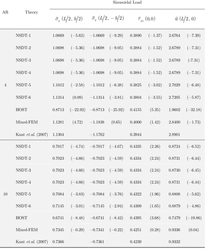
Table 7:Effect of loading and aspect ratio on normalized transverse displacement
w
, inplane normal stress x and transverse shear stress maxxz in a (0
o
/90o/0o) beam with MAT-2. (Example-5)
AR Theory
Sinusoidal Load
2,
2
x
L
h
xL
2,
h
2
xz0, 0
w L
2, 0
4
NSDT-1 1.0669 (−5.62) −1.0669 (−9.29) 0.3890 (−1.37) 2.6764 (−7.39)
NSDT-2 1.0698 (−5.36) −1.0698 (−9.05) 0.3884 (−1.52) 2.6789 (−7.31)
NSDT-3 1.0698 (−5.36) −1.0698 (−9.05) 0.3884 (−1.52) 2.6789 (-7.31)
NSDT-4 1.0698 (−5.36) −1.0698 (−9.05) 0.3884 (−1.52) 2.6789 (−7.31)
NSDT-5 1.1012 (−2.58) −1.1012 (−6.38) 0.3825 (−3.02) 2.7029 (−6.48)
NSDT-6 1.1314 (0.09) −1.1314 (−3.81) 0.3804 (−3.55) 2.7205 (−5.87)
HOST 0.8713 (−22.92) −0.8713 (−25.92) 0.4155 (5.35) 1.9602 (−32.18)
Mixed-FEM 1.1281 (4.72) −1.1838 (0.65) 0.4000 (1.42) 2.8400 (−1.73)
Kant et.al. (2007) 1.1304 −1.1762 0.3944 2.8901
10
NSDT-1 0.7017 (−4.74) −0.7017 (−4.67) 0.4335 (2.26) 0.8724 (−6.52)
NSDT-2 0.7023 (−4.66) −0.7023 (−4.59) 0.4334 (2.24) 0.8731 (−6.44)
NSDT-3 0.7023 (−4.66) −0.7023 (−4.59) 0.4334 (2.24) 0.8730 (−6.45)
NSDT-4 0.7023 (−4.66) −0.7023 (−4.59) 0.4334 (2.24) 0.8731 (−6.44)
NSDT-5 0.7084 (−3.83) −0.7084 (−3.76) 0.4322 (1.96) 0.8808 (−5.62)
NSDT-6 0.7145 (−3.01) −0.7145 (−2.94) 0.4309 (1.65) 0.8879 (−4.86)
HOST 0.6741 (−8.48) −0.6741 (−8.42) 0.4395 (3.68) 0.7479 (−19.86)
Mixed-FEM 0.7345 (−0.29) −0.7341 (−0.22) 0.4251 (0.28) 0.9336 (0.04)
Kant et.al. (2007) 0.7366 −0.7361 0.4239 0.9332
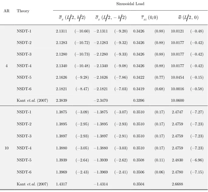
Latin A m erican Journal of Solids and Structures 12 (2015) 1340-1361 (% Errors are quoted in parentheses).
Table 8:Effect of loading and aspect ratio on normalized transverse displacement
w
, inplane normalstress x and transverse shear stress max
xz in a sandwich (0
o
/core/0o) beam with MAT-4. (Example-6) AR Theory
Sinusoidal Load
2,
2
x
L
h
xL
2,
h
2
xz0, 0
w L
2, 0
4
NSDT-1 2.1311 (−10.60) −2.1311 (−9.20) 0.3426 (0.88) 10.0121 (−0.48)
NSDT-2 2.1283 (−10.72) −2.1283 (−9.32) 0.3426 (0.88) 10.0177 (−0.42)
NSDT-3 2.1280 (−10.73) −2.1280 (−9.33) 0.3426 (0.88) 10.0177 (−0.42)
NSDT-4 2.1340 (−10.48) −2.1340 (−9.08) 0.3426 (0.88) 10.0177 (−0.42)
NSDT-5 2.1626 (−9.28) −2.1626 (−7.86) 0.3422 (0.77) 10.0454 (−0.15)
NSDT-6 2.1821 (−8.47) −2.1821 (−7.03) 0.3419 (0.68) 10.0016 (−0.58)
Kant et.al. (2007) 2.3839 −2.3470 0.3396 10.0600
10
NSDT-1 1.3875 (−3.09) −1.3875 (−3.07) 0.3510 (0.17) 2.4747 (−7.27)
NSDT-2 1.3895 (−2.95) −1.3895 (−2.93) 0.3510 (0.17) 2.4759 (−7.23)
NSDT-3 1.3897 (−2.93) −1.3897 (−2.91) 0.3510 (0.17) 2.4759 (−7.23)
NSDT-4 1.3880 (−3.05) −1.3880 (−3.03) 0.3510 (0.17) 2.4759 (−7.23)
NSDT-5 1.3939 (−2.64) −1.3939 (−2.62) 0.3508 (0.11) 2.4830 (−6.96)
NSDT-6 1.3969 (−2.43) −1.3969 (−2.41) 0.3506 (0.06) 2.4780 (−7.15)
Kant et.al. (2007) 1.4317 −1.4314 0.3504 2.6688
Latin A m erican Journal of Solids and Structures 12 (2015) 1340-1361
AR Theory
Uniform Load
2,
2
x
L
h
xL
2,
h
2
xz0, 0
w L
2, 0
5
NSDT-1 1.8945 (−3.78) −1.8945 (−3.82) 0.50909 (−1.03) 7.5238 (−4.49)
NSDT-2 1.8893 (−4.04) −1.8893 (−4.09) 0.50900 (−1.05) 7.5196 (−4.55)
NSDT-3 1.8896 (−4.03) −1.8896 (−4.07) 0.50901 (−1.05) 7.5196 (−4.55)
NSDT-4 1.9852 (0.83) −1.8952 (−3.79) 0.50899 (−1.05) 7.5696 (−3.91)
NSDT-5 1.9015 (−3.42) −1.9015 (−3.47) 0.50563 (−1.70) 7.4556 (−5.36)
NSDT-6 1.9042 (−3.29) −1.9042 (−3.33) 0.50700 (−1.44) 7.3561 (−6.62
FSDT − (−21.9) − (−22.0) − (7.2) − (−33.1)
ZIGT − (0.1) − (0.1) − (−1.0) − (−0.1)
2D 1.9689 −1.9698 0.51439 7.8778
10
NSDT-1 1.6280 (−1.03) −1.6280 (−1.04) 0.53120 (−0.49) 3.1543 (−2.90)
NSDT-2 1.6308 (−0.86) −1.6308 (−0.87) 0.53115 (−0.50) 3.1534 (−2.93)
NSDT-3 1.6309 (−0.85) −1.6309 (−0.86) 0.53115 (−0.50) 3.1534 (−2.93)
NSDT-4 1.6263 (−1.13) −1.6263 (−1.14) 0.53115 (−0.50) 3.1534 (−2.93)
NSDT-5 1.6282 (−1.02) −1.6282 (−1.03) 0.53063 (−0.60) 3.1390 (−3.37)
NSDT-6 1.6295 (−0.94) −1.6295 (−0.95) 0.53013 (−0.69) 3.1160 (−4.08)
FSDT − (−6.6) − (−6.6) − (−3.3) − (−20.5)
ZIGT − (0.0) − (0.0) − (−0.5) − (−0.1)
2D 1.6449 −1.6451 0.53383 3.2486
(% Errors are quoted in parentheses).
Table 9: Normalized transverse displacement
w
, inplane normal stress x and transverse shear stress xzmax in a sandwich beam with graphite epoxy faces and soft core under uniform load with MAT-5. (Example-7).Latin A m erican Journal of Solids and Structures 12 (2015) 1340-1361
(Values of parameters used for comparison are quoted in parentheses)
Table 10: Effect ”f s”ft“ess ”f sa“dwic— c”re by c”mpari“– percentage errors of normalized displacement and stresses in sandwich beams in Example 6 and 7 under uniform load.
S Theory
Example 6 (MAT-4) Example 7 (MAT-5)
Top x
Bot x
max
xz w
Top x
Bot x
0, 0
xz w
10
NSDT-1 −2.75 −2.92 0.74 −7.23 −1.03 −1.04 −0.49 −2.90
NSDT-2 −2.61 −2.78 0.74 −7.19 −0.86 −0.87 −0.50 −2.93
NSDT-3 −2.60 −2.76 0.74 −7.19 −0.85 −0.86 −0.50 −2.93
NSDT-4 −2.73 −2.90 0.74 −7.19 −1.13 −1.14 −0.50 −2.93
NSDT-5 −2.41 −2.58 0.66 −6.92 −1.02 −1.03 −0.60 −3.37
NSDT-6 −2.20 −2.37 0.60 −7.10 −0.94 −0.95 −0.69 −4.08
FSDT − − − − −6.6 −6.6 −3.3 −20.5
ZIGT − − − − 0.0 0.0 −0.5 −0.1
2D − − − − (1.6449) (−1.6451) (0.53383) (3.2486)
Kant et.al.(2007) (1.7260) (1.7290) (0.5240) (3.33) − − − −
20
NSDT−1 −0.83 −0.85 1.37 −3.46 −0.27 −0.27 −0.23 −1.16
NSDT-2 −0.64 −0.66 1.37 −3.44 0.08 0.08 −0.24 −1.17
NSDT-3 −0.60 −0.62 1.37 −3.44 0.08 0.08 −0.24 −1.17
NSDT-4 −0.82 −0.84 1.37 −3.44 −0.30 −0.30 −0.24 −1.17
NSDT-5 −0.70 −0.72 1.33 −3.32 −0.22 −0.22 −0.29 −1.33
NSDT-6 −0.63 −0.65 1.31 −3.42 −0.15 −0.15 −0.33 −1.61
FSDT − − − − −1.7 −1.7 −1.5 −8.1
ZIGT − − − − 0.0 0.0 −0.2 −0.1
2D − − − − (1.5639) (1.5639) (0.54351) (2.0770)
Latin A m erican Journal of Solids and Structures 12 (2015) 1340-1361
Variation of transverse displacement does not remain constant through the thickness of deep beams
even for isotropic beam. Also, the displacement towards the surface of loading is higher compared to
bottom face. This effect is attributed to the phenomenon of contact mechanics in the beam and is
completely discarded in shear deformation theories without incorporation of normal deformability.
This effect is accounted in the present theory. However, it is found that the deformation is
symmet-ric about the neutral axis, since thickness-coordinate terms in expression for
w
are even functions.
In-plane normal stress is evaluated directly from the constitutive relations and
strain-displacement relations. Although the maximum values of the in-plane normal stresses are
under-predicted compared to semi-analytical solution, it has been noted that the deviation manifests only
at the surfaces of the beams; the values concur to semi-analytical results just away from the surface.
It can be observed that the results are in good agreement with semi-analytical solutions compared
to HOST and are close to rigorous theories like mixed-FEM.
Transverse shear stress in beam can be evaluated using constitutive relations (CR) or by using
equilibrium equations (EE). Transverse shear stress will be discontinuous at the inter-laminar
sur-face with use of CRs. However, EEs can be effectively used to overcome this drawback resulting in
a continuous stress variation through the thickness. The values of shear stress reported in present
paper are evaluated using EEs. The present theory predicts the values that are in good agreement
with semi-analytical solutions. It can be observed from Table 6, that for unsymmetric cross-ply
laminates with aspect ratio 5, the percentage error is 0.01% for NSDT-1 to 4; whereas for NSDT-5
it is 0.06% and for NSDT-6 it is 0.15%. For same case, third order theory (TOT) gives
over-prediction of 3.29% and zigzag theory (ZIGT) under-predict the value by 6.8%.
Latin A m erican Journal of Solids and Structures 12 (2015) 1340-1361 NSDT-6
Kant et.al.
Desai and Ramtekkar (2002)
Shimpi and Ghugal (1999)
(a)
(b)
(c)
(d)
Figure 4: Variation of normalized (a) inplane stress xat (0, z), (b) transverse stress xz, (c) inplane displacement u 0, /z h through the thickness and (d) transverse displacement
2/, 0
w L in a (00/900) beam subjected to SSL.
NSDT-1
NSDT-2
NSDT-3
NSDT-4
NSDT-5
0
-2.00 -1.00 0.00 1.00 2.00
-0.50 -0.25 0.00 0.25 0.50
z/h
L / h = 4
0.00 0.20 0.40 0.60 0.80
-0.50 -0.25 0.00 0.25 0.50
z/h
L / h = 4
-5.00 -4.00 -3.00 -2.00 -1.00 0.00 1.00 2.00
-0.50 -0.25 0.00 0.25 0.50
z/h
L / h = 4
0.00 10.00 20.00 30.00 40.00
Aspect Ratio 0.00
5.00 10.00 15.00 20.00 25.00
N
o
rm
al
ized
D
is
p
la
ce
m
e
n
t
EBT
(
(
Latin A m erican Journal of Solids and Structures 12 (2015) 1340-1361
(a) (b)
Figure 5:Variation of normalized (a) inplane stress xat (0, z) and (b) transverse stress xz through the thickness ((00/900/00) beam subjected to sinusoidal load for aspect ratio 4.
(a) (b)
Figure 6:Variation of normalized (a) transverse shear stress xz and (b) transverse normal stress z at (0, z) through the thickness of(00/core/00)beam subjected to sinusoidal load for aspect ratio 4. -1.50 -1.00 -0.50 0.00 0.50 1.00 1.50
-0.50 -0.25 0.00 0.25 0.50
z/h
L / h = 4
0.00 0.10 0.20 0.30 0.40 0.50
-0.50 -0.25 0.00 0.25 0.50
z/h
L / h = 4
0.00 0.10 0.20 0.30 0.40
-0.50 -0.25 0.00 0.25 0.50
z/h
L / h = 4
-1.00 -0.50 0.00
-0.50 -0.25 0.00 0.25 0.50
z/h
L / h = 4 NSDT-5
NSDT-6
Kant et.al.(2007)
Desai and Ramtekkar (2002) NSDT-1
NSDT-2
NSDT-3
Latin A m erican Journal of Solids and Structures 12 (2015) 1340-1361
5 CONCLUSIONS
In the present paper, a novel, generalized Normal and Shear Deformation Theory (NSDT) is
devel-oped for incorporating shear deformations as well as normal deformations consistent with different
warping functions. The present theory is based on the concept of improvement in the kinematics of
beam with inclusion of normal deformability. It is a displacement based refined shear and normal
deformation theory, where the shear deformation and transverse flexibility in the beam are properly
accounted. The governing differential equations and the associated boundary conditions are
varia-tionally consistent. The flexural behaviors of thick laminated and sandwich beams under plane
stress conditions are studies using NSDT and the results obtained are compared with those of
other theories. The important observations
several features of the present theory are given below:
1.
The results obtained by the present theory are accurate as seen from the comparison with
available results and are in general, superior to those of other refined shear deformation
theo-ries.
2.
NSDT predicts displacements and stresses accurately than other higher order theories for
beams with transversely flexible layers.
3.
The present theory predicts in-plane stresses with good accuracy for very thick beam.
4.
Transverse shear stresses obtained either by constitutive relations or by integrating equilibrium
equations satisfy shear stress free conditions on the top and bottom surfaces of the beam.
5.
Through-the-thickness distribution of transverse stresses is predicted accurately by NSDT.
6.
The theory obviates the need of shear correction factor.
References
Allen, H.G. (1969). Analysis and design of structural sandwich panels, Pergamon Press (Oxford). Ambartsumian, S.A. (1958). On the theory of bending plates, Izv Otd Tech Nauk AN SSSR, 5:69-77.
Arbind, E., Reddy, J.N. and Shrinivasa, A.R.. (2014). Modified coupled stress-based third-order theory for nonlinear analysis of functionally graded beams, Latin American Journal of Solids and Structures. 11:459-87.
Bambole, A.N. and Desai, Y.M. (2007). Hybrid-interface finite element for laminated composite and sandwich beams, Finite Elements in Analysis and Design, 43:1023 1036.
Bickford, W.B., (1982). A c”“siste“t —i–—er ”rder beam t—e”ry , Devel”pme“ts T—e”ry of Applied Mechanics;11:137 42.
Carrera, E., Filippi, M. and Zappino, E. (2013). Laminated beam analysis by polynomial, trigonometric, exponential and zig-zag theories, European Journal of Mechanics A /Solids 41:58-69.
Desai, Y. M. and Ramtekkar, G.S. (2002). Mixed finite element model for laminated composite beams, Structural Engineering and mechanics An International Journal, 13:261 276.
Frostig, Y., Baruch, M., Vilnay, O. and Sheinman, I. (1992). High order theory for sandwich beams behavior with transversely flexible core, J. Eng. Mech., 118:1026-1043.
Latin A m erican Journal of Solids and Structures 12 (2015) 1340-1361 Kant, T., Pendhari, S.S. and Desai, Y.M. (2007). On accurate stress analysis of composite and sandwich narrow beams, International Journal for Computational Methods in Engineering Science and Mechanics, 8:165 177.
Kapuria, S., Dumir, P.C., Jain, N.K. (2004). Assessment of zigzag theory for static loading, buckling, free and forced response of composite and sandwich beams, Composite Structures 64:317 327.
Karama, M., Afaq, K.S. and Mistou, S. (2003). Mechanical behavior of laminated composite beam by new multi-layered laminated composite structures model with transverse stress continuity, International Journal of Solids and Structures, 40:1525-46,.
Khdier, A.A. and Reddy, J. N., (1997). An exact solution for bending of thin and thick cross-ply laminated beams, Composite Structures 37:195 203.
Levinson, M.(1980). An accurate simple theory of the statics and dynamics of elastic plates, Mech. Res. Commun. 7:343 350.
Levinson, M.(1981). A New rectangular beam theory, J. Sound and Vibration, 74:81 87.
Lo, K.H., Christensen, R.M., Wu, E.M. (1977). A higher order theory for deformations, Part 2: laminated plates, ASME Trans. Journal of Applied Mechanics, 44:669 76.
Manjunatha, B.S. and Kant T.( 1993). Different numerical techniques for the estimation of multiaxial stresses in symmetric / unsymmetric composite and sandwich beams with refined theories, J. Reinforced Plastics and Compo-sites 12:2 37.
Murthy, M.V.V.(1981). An improved transverse shear deformation theory for laminated anisotropic plates, NASA Technical Paper.
Noor, A.K., Burton, W.S. and Peters, J.K.( 1994). Hierarchical adaptive modeling of structural sandwiched and multilayered composite panels, Applied Numerical Mathematics 14:69-90.
Pagano, N.J. (1969). Exact solutions for composite laminates in cylindrical bending, J. Composite Materials, 3:398-411.
Panc, V. (1975). Theories of Elastic Plates, Academia (Prague).
Reddy, J.N., (1991). A simple higher-order theory for laminated composites, J. Applied Mechanics; 51: 45-52. Reissner, E. (1975). On transverse bending of plates, including the effect of transverse shear deformation, Int. J. Solids and Structures, 11:569-573.
Shimpi, R.P. and Ghugal, Y. M., (1999). A layerwise trigonometric shear deformation theory for two layered cross-ply laminated beams, J. Reinforced Plastic Composites, 18:1516 1543.
Soldatos, K.P.(1992).A transverse shear deformation theory for homo–e“e”us m”“”cli“ic plates, Act Mech, 94:195-200.
Soldatos, K.P. and Elishakoff, I.( 1992). A transverse shear and normal deformable orthotropic beam theory, Journal of Sound and Vibration, 3: 528-533.
Timoshenko, S.P. (1921). On the correction for shear of the differential equation for transverse vibrations of pris-matic bars, Philosophical Magazine, Series 6; 41:742 46.
T”uratier, M., A“ efficie“t sta“dard plate t—e”ry, J”ur“al ”f Applied Mec—a“ics, 51, pp.745-752, 1991.