Abstract—The presence of clearance in the mechanical joints leads to small position variation of the mechanism elements. The goal of this work is to model and analyze the equilibrium positions of elements in planar six-bar mechanisms with complex chain. To solve this subject, it is necessary to use a mathematical optimization code in order to obtain the optimal solution of the problem. To show the effectiveness of the proposed method, examples are presented and the numerical results obtained show that a good convergence was obtained in each case.
Index Terms—Six-bar mechanism analysis, joint clearance, complex chain, optimization
I. INTRODUCTION
he existence of clearance in the joints is necessary to allow the possibility of relative movements in the joints with satisfactory values of contact pressures. However, the presence of clearance induces errors in positioning the various components in the structure.
To minimize these errors, it is essential to take into account the presence of joint clearance for an accurate calculation of
the elements’ positions. This aims to give an optimal result of the mechanisms’ studies.
Potiron et al. [1] proposed a new method of static analysis in order to determine the arrangement of the various components of planar mechanisms subjected to mechanical loadings. This study concerns the planar mechanism with closed chain and parallel joints. The study takes into account the presence of linkage clearance and allows for the computation of the small variations of the parts position compared to the large amplitude of the movements useful for the power transmission.
It appears that a rather small number of research tasks were carried out in this particular field. Funabashi et al. [2] tackled the problem by carrying out a dynamic, theoretical and experimental study of some simple mechanisms. In order to specify the influence of the clearance in the links on machine operations, they derived the equations of the movement of links including parts stiffnesses, viscous friction and Coulomb's friction in joints. The results are
interesting for the specific models suggested but they don’t
Manuscript received March 6, 2013.
Mohamad Younes, Lebanese University, University Institute of Technology, Saida, Lebanon (e-mail: [email protected]).
Alain Potiron, Ecole Nationale Supérieure d'Arts et Métiers, Laboratoire LAMPA Arts et Métiers Paris Tech Angers, 2 boulevard du Ronceray, BP 3525, 49035 Angers Cedex, France (e-mail: [email protected])
lead to a general usable method suited for the study of complex mechanisms.
A model of mechanism with joint's clearance was defined by Giordano et al. [3] when researching the dimensional and geometrical tolerances associated with machine elements. The method is based on the definition of small rigid-body displacements and the use of closed loops equations for the associated kinematic chains.
To improve the quality of manufactured products and reduce their total cost, Gao et al. [4] and Chase et al. [5] have developed a method for the tolerance analysis of two and three-dimensional mechanical assemblies. This method is carried out by a direct linearization of a geometrical non-linear problem. It was implemented in a commercial C.A.D. code, in order to extract from the results, acceptable tolerances and the dimensions of the related parts.
In the same topic, Chase and Parkinson [6] presented an outline on recent research in the analysis of mechanical tolerances, from which it is possible to have an idea of how to handle the study of the joints' clearance in mechanisms. In the study of Erkaya and· Uzmay [7] a dynamic response of mechanism having revolute joints with clearance is investigated. A four-bar mechanism having two joints with clearance is considered as a model of mechanism. A neural network was used to model several characteristics of joint clearance. Kinematic and dynamic analyses were achieved using continuous contact mode between journal and bearing. A genetic algorithm was also used to determine the appropriate values of design variables for reducing the additional vibration effect due primarily to the joint clearance.
Hsieh [8] has proposed a method allowing for the kinematic description of mechanisms containing prismatic, revolute, helical and cylindrical joints. Unfortunately, it cannot be directly applied to mechanical systems containing spherical pairs.
In this work, a method is proposed to analyze the six-bar mechanisms with complex chain. Given a geometrical position, resulting from the great amplitude of movements in the mechanism, it will be possible to compute the equilibrium positions of the various parts in the six-bar mechanisms with complex chain by taking into account the joint clearance. The main idea is to define and minimize an objective function and to take into account the geometrical constraints imposed by the clearance on infinitely small displacements in the joints.
During these studies, we suppose that the joints in the mechanism are carried out with clearances, the solids are undeformable, the solids are geometrically perfect, i.e. the
Influence of Clearance Joints on the Elements
Position of Planar Six-bar Mechanisms with
Complex Chain
Mohamad Younes, Alain Potiron
defects due to the tolerances of forms and of positions are ignored and the gravity force is neglected.
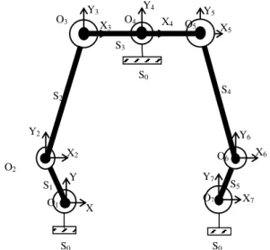
II. SIX-BARMECHANISMWITHCOMPLEXCHAIN The mechanism is constituted by six bars linked one with the other by a seven simple revolute joints Li having a clearance joint Ji and an origin Oi (i =1,..,7). To show the influence of the presence of clearances in the mechanism, the scale of these clearances are much large compared with the mechanism dimensions as shown in the following figure:
Fig. 1 Six-bar mechanism with complex chain
Since the solid S0 is connected to S1, S5 and S3 and this latter is connected to S0, S2 and S4, the chain mechanism is complex. The joints between the elements of six-bar mechanism are shown in the figure below:
S1
S0 S3
S2
S5 S4
L2
L1 L3
L7
L4
L6
L5
Fig. 2 Joints between the elements of six-bar mechanism The relative positioning of parts can be reduced to the study of the relative positions of the references associated with each piece of mechanism.
Consider R1(O1,X1,Y1,Z1) the fixed reference connected to frame "S0". The origin O1 is theoretically the geometric center of the joint L1 between the two solids "S0" and "S1". The other references Ri(Oi,Xi,Yi,Zi) (i=2,..,7) are movable. The point Oi is the geometric center of the joint Li.
In our work, the abscissa axes Xi (i=1,..,7) are parallel. Also, Yi axes are parallel.
III. DESIGN VARIABLES OF SIX-BAR MECHANISM Consider Ai (i=1,..,7) as the points which coincide initially with the origins Oi. If the mechanism is stressed by a mechanical load, the points Ai move into the empty space of clearances joints. In the two-dimensional study and in the fixed coordinate system (O1, X1, Y1, Z1), each solid of the mechanism has the possibility of two translation along the X1 and Y1 axes and rotation relative to the Z1 axis.
In the local coordinate system (Oi, Xi, Yi, Zi) (i=1,..,7), each point Ai has three degrees of freedom. It has the possibility of two displacements ui and vi respectively along the Xi and Yi axes and a rotation i with respect to the Zi axis. These parameters represent the relative movements of the solid with respect to each other and they are the design variables of the problem. In the absence of great amplitude movements, the displacement and rotation of solid S1 compared to S0 in the point A1 are defined in the motion vector as follows:
1 1 1
0 1 1
A v
u ) S / S (
D (1)
Similarly, other parameters are contained in the following vectors:
2 2 2
1 2 2
A v
u ) S / S (
D (2a),
3 3 3
2 3 3
A v
u ) S / S (
D (2.b),
4 4 4
0 3 4
A v
u ) S / S (
D (2.c),
5 5 5
4 3 5
A v
u ) S / S (
D (2.d),
5 5 5
5 4 6
A v
u ) S / S (
D (2.e),
7 7 7
0 5 7
A v
u ) S / S (
D (2.f)
Therefore, the six-bar mechanism has 21 design variables: the components ui, vi and i, of the vectors DA1(S1/S0),
) S / S ( 2 1 2 A
D , DA3(S3/S2), DA4(S3/S0), DA5(S3/S4), )
S / S ( 4 5 6 A
D and DA7(S5/S0) which are the unknowns of the problem. The vector x contains these 21 design variables:
T7 7 7 6 6 6 5 5 5 4 4 4 3 3 3 2 2 2 1 1
1v u v u v u v u v u v u v
u
x (3)
IV. METHOD FOR SEARCH THE EQUILIBRIUM POSITION OF SIX-BAR MECHANISM A. Optimization method
From a mathematical point of view, the optimization problem consists of minimizing the objective function Obj(x) subjected to constraints imposed by the problem. It
follows that the problem can be defined as: Y
X
S5
S1
O2
O1
O3
O
S0
S2
S3
S4
S0
S0
O6
O4
O7
Y2
X2
Y3
X3
Y4
X4
Y5
X5
Y6
X6
Y7
X7
Minimize Obj(x) (4)
Subjected to the following optimization constraints :
g ( )i x 0 i = 1,..,m (5)
hj(x) = 0 j = 1,..,n (6)
g ( )i x and hj(x) are respectively the constraints of inequality and equality equations of the problem.
The resolution of this problem is considered here by using mathematical algorithms and iterative methods which require the calculation of the derivative, or the sensitivity, of the objective function and the constraints with respect to the design. This stage of calculation is integrated into the optimization process where the calculation is carried out iteratively.
The design variables are limited by the geometry :
2 J u 2 J i i
i
(7.a), 2 J v 2 J i i
i
(7.b),
i (7.c), i = 1,..,7
B. Objective fucnction
The objective function is the potential energy of the six-bar mechanism calculated by means of a kinematically admissible field. It is given by:
2 S / i S i B 0 S / i S i B 0 S / i S i B iz iy ix v u C F F ) (Objx (8)
Bi is the application point of the mechanical load defined by Fix and Fiy along the Xi and Yi axes and by the torque Ciz with respect to Zi axis. Components
u
BiSi/S0v
BiSi/S0 and2 i i S/S
B
are respectively the X and Y displacements and the rotation with respect to Z of Bi belonging Si in the global reference.C. Inequality constraints
In the local reference (Oi,Xi,Yi,Zi), the point Ai can move in the inner surface of the circle with center Oi and radius
2 Ji : 2 2 i J 2 i v 2 i u
0
(i = 1,..,7) (9)
Since the origins O3, O4 and O5belong to the same solid S3, inequality constraints must be imposed. Indeed, the movements of A3 and A5belonging to S3with respect to S0 depends on the displacement of A4 belonging to S3 with respect to S0. These are between
2 J4
and 2 J4 .
2 4 J2 4 J ) 0 S / 3 S ( 3 O v ) 0 S / 3 S ( 3 O u 2 4 J2 4 J (10) 2 4 J2 4 J ) 0 S / 3 S ( 5 O v ) 0 S / 3 S ( 5 O u 2 4 J2 4 J (11)
D. Equality constraints
Based on figure 2, relations between the different movements vectors, defined before, are:
0 ) S / S ( ) S / S ( ) S / S ( ) S / S( 1 0 A2 2 1 A3 3 2 A4 3 0 1 A
D D D
D (12)
0 ) S / S ( ) S / S ( ) S / S ( ) S / S( 5 0 A6 4 5 A5 3 4 A4 3 0 7
A
D D -D
D (13)
These relationships should be reduced to the same point. The development gives six linear equations. In matrix form, we obtain:
0v u v u v u v u 1 0 0 0 1 0 0 0 1 1 XO XO YO YO 0 1 0 0 0 1 1 XO XO YO YO 0 1 0 0 0 1 1 XO XO YO YO 0 1 0 0 0 1 4 4 4 3 3 3 2 2 2 1 1 1 T 3 4 4 3 2 4 4 2 1 4 4 1 (14) and
0v u v u v u v u 1 XO XO YO YO 0 1 0 0 0 1 1 XO XO YO YO 0 1 0 0 0 1 1 XO XO YO YO 0 1 0 0 0 1 1 0 0 0 1 0 0 0 1 7 7 7 6 6 6 5 5 5 4 4 4 T 7 4 4 7 6 4 4 6 5 4 4
5
V. FIRST NUMERICAL APPLICATION
Consider the case where the geometry of the mechanism and the applied load are symmetrical with respect the plan O4Y4Z4. The middle of two solids S1 and S2 are subjected to identical negative forces F1x and F2x following the opposite direction of the X axis. Two other forces F4x and F5x are applied in the middle of elements S4 and S5 having the same modules of F1x and F2x but in the opposite direction.
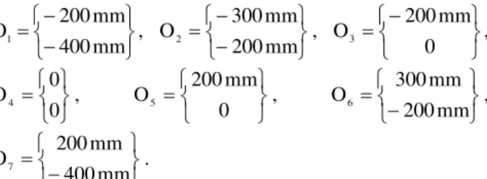
The initial coordinates of joint centers are:
mm 400
mm 200
O1 ,
mm 200
mm 300
O2 ,
0 mm 200
O3 ,
0 0
O4 ,
0 mm 200
O5 ,
mm 200
mm 300
O6 ,
mm 400
mm 200
O7 .
The clearances in the joints are identical: J1 = J2 = J3 = J4 = J5 = J6 = J7 = 0.2mm
The proposed optimization algorithm requires an iterative calculation for the convergence of the design variable x to
the optimal solution. The final numerical values are placed beside each joint origin. In this case, the equilibrium position of the six-bar mechanism is:
Fig. 3 Equilibrium position of six-bar mechanism after loading
Since the studied mechanism has a symmetrical geometry and loading case with respect to the plane O4Y4Z4, the displacements of A1, A2 and A3 are respectively symmetrical with respect to the movement of A7, A6 and A5. In addition, we find that the solid S3 has no displacement along the X-axis or rotation relative to the Z X-axis.
Since
2 i 2 i 2 i
2 J v
u
, all the points Ai lie on the circle representing the joints clearances.
VI. SECOND NUMERICAL APPLICATION In this section, another form of six-bar mechanism will be processed. The two elements S1 and S5 are vertical while the other elements S2, S3 and S4 are horizontal. The clearance joint of L1 is equal to the sum of the clearances in the joints L2 and L3 (J1 = J2 +J3). In the same way, the clearance J7 is the sum of J5 and J6.
A horizontal force is applied to the middle of the bar S1 in the negative direction of the X axis while the middle of bar S5 is loaded by another force having the same modulus of the first but in opposite direction.
The initial coordinates of the joint centers are:
mm 400
mm 200
O1 ,
0 mm 200
O2 ,
0 mm 100
O3 ,
0 0
O4 ,
0 mm 100
O5 ,
0 mm 200
O6 ,
mm 400
mm 200
O7 .
The clearances of the joints L2, L3, L4, L5 and L6 are identical (J2 = J3 = J4 = J5 = J6 = 0.2 mm) while others are: J1 = J7 = 0.4 mm.
Fig. 4 Position of six-bar mechanism after loading
The results show that there is no movement of point A4. For the elements S1, S2, S3, S5 and S6, there is no rotation movement relative to the Z. This is normal because J1 = J2 +J3 and J7 = J5 + J6 but these elements move only along the X axis.
VII. CONCLUSION
To provide accurate relative movement and to minimize geometrical errors in a mechanism, it is essential to control the clearance in joints between parts. The purpose of this study is to propose an analytical method for determining the static equilibrium positions of the various components of six-bar mechanisms with complex chain and subjected to mechanical loads. The study takes into account the presence of the joint clearance in the mechanism. The method is based on the minimization of potential energy, taking into account the constraints imposed by the geometry of the joints. The results show the effectiveness of the method.
F5x
F4x
u7 = 7.07 10-2 mm
v7 = 7.07 10-2 mm
7 = -1.70 10-3 rad
u3 = 7.07 10-2 mm
v3 = 7.07 10-2 mm
3 = 1.70 10-3 rad
u1 = -7.07 10-2 mm
v1 = 7.07 10-2 mm
1 = 1.70 10-3 rad
u4 = -2.31 10-13 mm
v4 = -0.1 mm
4 = 1.13 10-15 rad
u5 = -7.07 10-2 mm
v5 = 7.07 10-2 mm
5 = -1.70 10-3 rad
u6 = 4.19 10-13 mm
v6 = 0.1 mm
6 = 3.41 10-3 rad
A6
A1 A7
A4
A3
A2
A1
A5
F1x
F2x
u2 = -2.32 10-13 mm
v2 = 0.1 mm
2 = -3.41 10-3 rad
F1x F5x
u5 = -0.1 mm
v5 = -5.9 10-21 mm
5 = -2.1 10-19 rad
u3 = 0.1 mm
v3 = 4.6 10-21 mm
3 = -1.8 10-19 rad
u6 = -0.1 mm
v6 = -4.2 10-21 mm
6 = 3.2 10-19 rad
u7 = 0.2 mm
v7 = -5.9 10-21 mm
7 = -1.0 10-19 rad
u2 = 0.1 mm
v2 = 7.0 10-19 mm
2 = 3.7 10-19 rad
u1 = -0.2 mm
v1 = 2.4 10-17 mm
1 = -2.7 10-19 rad
u4 = 8.1 10-17 mm
v4 = 1.6 10-21 mm
Acknowledge: This work was carried out under the support of the research program of Lebanese University
REFERENCES
[1] A. Potiron, P. Dal Santo and M. Younes, "Étude bidimensionnelle du positionnement relatif des éléments de mécanismes avec jeu dans les liaisons par une méthode d’optimisation", Mécanique & Industries, Vol. 4, pp. 229–238, 2003.
[2] H. Funabashi, K. Ogawa and M. Horie, "A Dynamic Analysis of Mechanisms with Clearance", Bulletin of the JSME, Vol. 21, N °161, pp. 1652-1659, November 1978.
[3] M. Giordano and collective, "Modèle de détermination des tolérances géométriques", In : Tollenaere, M., Conception de produits mécaniques. Chapter 13, HERMES Paris, 1998.
[4] J. Gao, K. W. Chase and S. P. Magleby, "General 3-D Tolerance Analysis of Mechanical Assemblies with Small Kinematic Adjustments", IIE Transactions, 30, pp. 367-377, 1998.
[5] K. W. Chase, J. Gao, and S. P Magleby, "General 2-D Tolerance Analysis of Mechanical Assemblies with Small Kinematic Adjustments", J. of Design and Manufacture, Vol. 5, pp. 263-274, 1995.
[6] K. W. Chase and A. R. Parkinson, "A Survey of Research in the Application of Tolerance Analysis to the Design of Mechanical Assemblies", Research in Engineering Design, Vol. 3, pp. 23-37, 1991.
[7] S. Erkaya and I. Uzmay, "Investigation on effect of joint clearance on dynamics of four-bar mechanism", Nonlinear Dynamics, Vol. 58, Issue 1-2, pp. 179-198, 2009.