J
OURNAL OFN
ANO-
ANDE
LECTRONICP
HYSICS Р А А-
А РVol.
6
No 3, 03051(4pp) (2014)
То
6
№
3, 03051(4cc) (2014)
The article was reported at the International Conference «The Advanced Technology, Equipment and Analytical Systems for Materials», Kursk, 13-14 May, 2014
2077-6772/2014/6(3)03051(4)
03051-1
2014
Sumy State University
Revisiting the Provision of Nanoscale Precision of Cutting on the Basis of Dynamic
Characteristics Modeling of Processing Equipment
A.G. Ivakhnenko, E.O. Ivakhnenko, A.Yu. Altukhov, V.V. Kuts
South-West State University, 94, 50 Let Oktyabrya Str., 305040 Kursk, Russia
(Received 19 May 2014; published online 15 July 2014)
The article deals with the issues related to the development of the processing equipment providing na-noscale precision of cutting by means of turning and milling. Building of a machine dynamic model is car-ried out to solve of this task. This allows taking into account the dynamic characteristics of the existing or designed equipment and the errors of dynamic setting of the machine and this also allows providing pro-cessing precision in nanometer range.
Keywords: Nanoscale precision, Turning machine, Dynamic model, Cutting
PACS numbers: 62.25. + g, 02.70. – c, 81.07. – b, 81.40. – z
1.
INTRODUCTION
Global high-tech production is already posing and
solving the tasks of producing hardware, which are
characterized by manufacturing errors with values less
than 100 nm. For quite a long period of time there have
been technologies, equipment, tools and
instrumenta-tion to achieve nanoscale precision, based on the
im-plementation of honing, polishing, burnishing and
addi-tional pass finishing processes. Their use has allowed
achieving the values of the roughness parameters
Ra
less than 2 nm. However, these processes are classified
as finishing operations and basically do not allow
con-trolling sizing errors and geometric form while
pro-cessing. Widely known and used fine diamond turning
processes, implemented using existing technologies,
equipment and cutting tools, give an opportunity of
pre-cision only in the micrometer range. In this connection
the issues related to the development of the processing
equipment providing nanoscale precision of processing
using turning and milling methods are of great interest
and importance. The solution of these tasks is not
pos-sible without taking into account the dynamic
charac-teristics of the existing or designed equipment and the
errors of dynamic setting of a machine.
2.
DESCRIPTION OF THE SUBJECT AND THE
METHODS OF THE RESEARCH
As it is known, the generalized mathematical model
of vibrations of cutting machine units can be
repre-sented in matrix form [1-6]
(1)
where
M
is the mass matrix of the machine units;
H
is
the damping coefficient matrix;
C
is the machine
stiff-ness matrix;
are the vectors of the vibratory
dis-placement of the machine units and their first and
se-cond derivatives;
F
is the vector of vibro-perturbations.
Further arguments and conclusions are based on
the analysis of the dynamic model of a turning machine
(Fig. 1). To simplify the calculations, we assume that
the machine consists of three units: a spindle unit with
a fixed workpiece (unit 0); frame (unit 1) and cutting
unit (unit 2).
With the same purpose we will consider vibrations of
the machine units in the transverse direction, then the
matrices
M
,
H
,
C
, the vectors and will take the form
[
]
,
[
]
,
C
[
]
[
]
,
[
]
,
[
]
,
[
]
,
(2)
where
m
i,
h
i,
c
iare the reduced mass, the damping
coef-ficient, stiffness coefficients of
i-
th unit of the machine;
is the cutting force;
is the force caused by
the presence of static imbalance of rotating workpiece
Fig. 1– Generalized model of vibrations of turning machine units
,
(3)
A.G. IVAKHNENKO, E.O. IVAKHNENKO, ET AL.
J.
N
ANO-
E
LECTRON.
P
HYS. 6
, 03051 (2014)
03051-2
The component error value of the workpiece in the
transverse section (
) in this case will be determined by
the expression (see Fig. 1)
-
,
(4)
and includes sizing error, waviness and roughness of
the machined surface.
Equation (1) using the Fourier integral
transfor-mation, can be reduced to the form
,
(5)
where
i
is the imaginary unit;
X
(),
F
() are the
com-plex amplitude spectra of vibration displacement and
perturbation, respectively.
Expression
is the matrix of the
dynamic stiffness of the machine. After the
transfor-mation of equation (5) we get the following expression
,
(6)
where the expression in brackets is the matrix of the
dynamic compliance of the machine
.
(7)
Applying to equation (4) the Fourier integral
trans-formation, we obtain
-
(8)
where
() is the complex amplitude spectrum of the
component error value;
x
0() and
x
2() are the
compo-nents of the vector
X
().
Writing equation (8) with regard to the expression
(6), we obtain
[
]
[
]
,
(9)
where
w
ijis the dynamic compliance matrix
compo-nents
W
(
),
i is
the line number,
j
is the column
num-ber, respectively.
Rearranging the elements in expression (9) we
fi-nally get
.
(10)
The value
() is a complex one, and, therefore, for
the estimation of the machined surface quality
parame-ters it is enough to have the peak values of the
compo-nent error elements.
It follows from the analysis of expression (8) that
high precision of processing can only be achieved if
there is no relative displacement of the cutting edge of
the tool and the workpiece during vibration, i.e. if
un-der the following condition
(11)
However, this condition cannot always be
achieva-ble in practice and determined from the linear model of
vibrations (1). Then equality (11) can be replaced by
x
0(
)
x
2(
)
≤
max, и и
(
)
≤
max,
(12)
where
max
is the required component error.
3.
EXPERIMENTAL RESULTS AND DISCATIONS
Condition (12) may be implemented using various
ap-proaches. Let us consider some of them for specific
dy-namic characteristics of the system ‘Machine, device, tool,
workpiece’ (MDTW) when component error
max
100 nm:
m
z
0,2 kg;
m
0
10 kg;
m
1
1000 kg;
m
2
1 kg;
c
0
2,5
10
6N/m;
c
1
6
10
6N/m;
c
2
25
10
6N/m;
h
0
400 kg/f;
h
1
4000 kg/f;
h
2
400 kg/f.
The first approach involves setting the values of
e
and
|
|
, then defining the rotational speed range
for which (12) is fulfilled.
Thus, if
e
= 100nm and
|
|
=10N, on the basis of
expression (10) the required component error can be
achieved at frequencies
from 1477 to 1740 rad/s and
more than 111,000 rad/s (Fig. 2), and, for example,
component error less than 50 nm can be achieved at
frequencies from 1,565 to 1,620 rad/s and more than
160,000 rad/s.
The second approach is to partition proportionally
the value
max
between the components in the
expres-sion
(10)
. Then the task of providing the precision of
processing can be solved through comprehensive
solu-tion of the subtasks of providing the precision within
the relevant components. Admitting, for example, that
the first component is 10 % of
max
, and the second one
is 90 %, from (12) we obtain two conditions
|
| |
|
and
(13)
|
| |
|
(14)
On the basis of the first condition (13) it is possible to
set an acceptable range of values of the specific imbalance
of the workpiece for different rotational speed ranges
| |
(15)
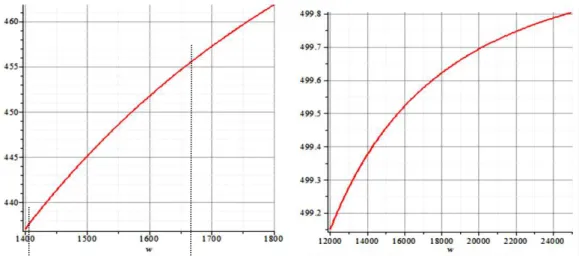
For example, on the basis of the second condition
(14) for the specified value
|
|
10 N the
compo-nent error less than 0,9
max
90 nm can be achieved at
frequencies from 1,487 to 1,723 rad/s and more than
12,050 rad/s (Fig. 3).
Based on the obtained rotational speed ranges,
us-ing (15) we get the restrictions to the maximum value
of the specific imbalance of the workpiece (Fig. 4).
The acceleration of the machine to the running
spindle rotational speed is associated with the passage
of the resonant speed
, which also imposes
re-strictions on the value of the specific imbalance of
ro-tating workpiece. Based on the given value of the
bear-ing clearance of the spindle unit
we get
|
|
4.
CONCLUSION
Thus, based on the modeling of the dynamic
charac-teristics of a turning machine it is possible to solve
comprehensively the task of providing the nanoscale
precision while cutting.
REVISITING THE PROVISION OF NANOSCALE PRECISION OF CUTTING
…
J.
N
ANO-
E
LECTRON.
P
HYS.
6
, 03051 (2014)
03051-3
Fig. 2− Dependence of the component error (nm) on the rotational speed (rad/s)
Fig. 3– Dependence of | | | |(nm) on the rotational speed (rad/s)
A.G. IVAKHNENKO, E.O. IVAKHNENKO, ET AL.
J.
N
ANO-
E
LECTRON.
P
HYS. 6
, 03051 (2014)
03051-4
REFERENCES
1. Ye.O. Ivakhnenko, Obespecheniye tochnosti obrabotki na tokarnykh stankakh posredstvom vybora ratsional'nykh rezhimov rezaniya s uchetom sostoyaniya dinamicheskoy sistemy SPID. Avtoref. diss. ... kand. tekhn. nauk (Khaba-rovsk: 1997) [in Russian].
2. A.G. Ivakhnenko, V.V. Kuts, Strukturno-parametricheskiy sintez tekhnologicheskikh sistem (Kursk. gos. tekhn. un-t.: Kursk: 2010) [in Russian].
3. A.G. Ivakhnenko, V.V. Kuts, Predproyektnyye issledova-niya metallorezhushchikh sistem (Yugo-Zapadnyy gosu-darstvennyy universitet: Kursk: 2013) [in Russian].
4. V.V. Kuts, Fundamental'nyye i prikladnyye problemy tekhniki i tekhnologii No 6 (284), 58 (2010) [in Russian]. 5. V.V. Kuts, S.V. Degtyarev, A.P. Kuz'menko,
O.G. Loktionova, Izvestiya Yugo-Zapadnogo gosudar-stvennogo universiteta. Seriya Tekhnika i tekhnologii No 1, 60 (2013) [in Russian].