Manufacturing of Long Thin Wall Tubes
of Small Bore with Titanium
Sukhwinder Singh Jolly
Abstract - In this paper material is assumed to be perfectly plastic and to obey the Von Mises Criterion of yielding. All of the possible parameters with the exception of diametric growth, which has a negligible effect, have been taken into account in determining the power and forces required. The analysis is applied to the case of making of long thin wall tubes of small bore with Titanium. The equation of volume constancy has been satisfied. The average yield stress value for titanium has been found with the help of curve fitting. Ductility of the material has also been improved.
Key words - Average yield stress, Ductility improvement, tube making., flow rate, %age reduction.
I. INTRODUCTION
In metal forming, material is plastically deformed and therefore one works in the plastic region of generalized true stress-strain curve that is between yield point and instability point. Therefore in metal forming, the working range is limited between the yield point and the instability point of the respective stress-strain curve of the material.
The analysis of tube making has been undertaken by several researchers. A brief description of the work done by other researchers on soft as well as hard-to-work materials is studied here. S. Kalpakcioglu (1961) has studied the mode of deformation and metal flow pattern by the distorted grid method and spinnability of metals. Kegg, R.L. (1961), on the other hand, has studied the spinnability of metals which is defined as the maximum percent reduction in thickness a material undergoes before fracture.
M. Hayama and H. Kudo (1979 I) have studied the diametral growth and working forces in tube spinning. M. Hayama and H. Kudo (1979 II) have also studied the mechanism of deformation in tube spinning on the basis of the observation of metal flow experimentally. R.P. Singhal, S.K. Das and Rajnish Prakash (1987) have studied the Shear spinning of long tubes which are axially pulled side by side. R.P. Singhal, P.K. Saxena and R. Prakash (1990) have presented a generalized expression for the estimation of the power required in the spinning of long tubes, in which the material is assumed to be perfectly plastic and to obey Von Mises criterion of yielding, and the tools are assumed to be rigid. R.P. Singhal and Rajnish Prakash (1990) have carried out an experimental study of shear spinning tubes made of hard-to-work materials. Shear spinning technology for manufacture of long thin wall tubes of small bore has been discussed by Rajnish Prakash and R.P. Singhal (1995). This new process is economically viable for producing tubes in high-strength materials, particularly when the volume of production is not high.
Quigley and Monaghan (2000) have presented solution to the difficulties that a finite element modelling of spinning faces. Gotoh and Yamashita (2001) have studied the effect of shearing speed on the quality of shape and edge-face of the sheared off products.
Sukhwinder Singh Jolly is currently Professor, Faculty of Mechanical Engineering, Bahra Group of Institutions, Bhedpura, Patiala (Punjab) INDIA ). Phone +91-98768-24666, E-mail : [email protected].
Levy, Van Tyne and String field (2004) have shown in their paper that with the increased use of tubular steel products, especially for hydro forming applications, it is important to be able to predict the performance of tube form sheet tensile stress. Jansson, Nilsson and Simonsson (2007) carried out the studies on process parameter estimation for the tube hydro forming process. Bortot, Ceretti and Giardini (2008) have studied the determination of flow stress of tubular material for hydro-forming applications. Mori, Ishiguru and Isomura (2009) have discussed about hot shear spinning of cast aluminium alloy parts in their paper.
II. DUCTILITY IMPROVEMENT
Experiments conducted by Bridgeman (1955) shows that hydrostatic pressure increase the ductility of metals and alloys. Ductility improvement under plane-strain conditions and actual strain conditions has been calculated.
A. Yield under plane-strain conditions
Plane strain is defined as a condition in which (a) the flow is everywhere parallel to a given plane, say the (x, y) plane, and (b) the motion is independent of z. Thus one principal strain-increment, say d2, is zero. It follows that if
there is no volume change d1= -d3, assuming no elastic
deformation, that is assuming an incompressible rigid-plastic material. The deformation is thus pure shear-strain. It is assumed that pure shear strain is produced by pure shear stress. Rowe (2000).
When we apply Von Mises yield criterion and upper bound technique, then it is convenient to suppose that the diameter of the tube remains constant, and that the wall thickness alone is changed during tube making. There is then no hoop strain, and plane-strain conditions can be assumed. Let d1, d2 and d3 be the principal components
of an increment of strain. Then
)
(
3
2
23 2 2 2
1
d
d
d
d
In uniaxial test
1 3 2
2
1
d
d
d
23 2
3 2
3
2
1
2
1
3
2
d
d
d
d
23 2 3 2 3
4
4
3
2
4
d
6
3
2
23
3 2
3
d
2
3
3
2
d
Thus
1
d
d
3
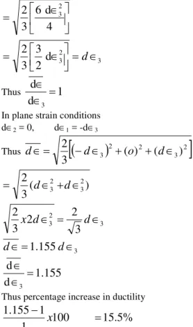
In plane strain conditions d2 = 0, d1 = -d3
Thus
3
2(
)
2(
3)
2
3
2
d
o
d
d
)
(
3
2
23 2
3
d
d
3 2
3
3
2
2
3
2
d
d
x
3
155
.
1
d
d
155
.
1
d
d
3
Thus percentage increase in ductility
15.5%
100
1
1
155
.
1
x
Thus, it shows that there is 15.5% increase in the ductility of the material with plane strain conditions. Thus, ductility of the material improves under plane strain conditions. Due to this the working range of hard-to-work materials increases. The presence of hydrostatic stress is contributory factor for increase in the ductility of the material.
III. AVERAGE YIELD STRESS CALCULATION
Fig. 1 Curve Fitting
The equation for stress is given by :
y = -0.96152 + 22.473-4.8909
The average stress is given by equation
y = 1/(a-b)
ad
b
= 1/(11-6) x 103
11
6
2
d
)
8909
.
4
473
.
22
9615
.
0
(
11 6 2
3 3
8909
.
4
2
/
473
.
22
3
/
0.9615
-10
x
1/5
= 1/5 x 103 [{-0.9615 (113/3) + 22.473 (112/2) -4.8909 (11)}– {-0.9615 (63/3) + 22.473 (62/2)– 4.8909 (6)}] = 1/5 x 103 [-.426.58 + 1359.6 – 53.80] – [-69.23 +
404.51-29.34]
= 1/5 x 103 [879.22– 305.94] = 1/5 x 103 [573.28]
y = 114.66 x 10 3
psi
y = 114.66 x 103 x 6.895 x 103 N/m2
(1 psi = 6.895 x 10³ N/m2)
y = 790.581 x 10 6
N/m2
y = 790.581 N/mm 2
~ 791 N/mm2= 791 MPa
IV. CRITERION
It is assumed that there is no build up of the material ahead of the roller. The deformation is localised in a small volume of the work piece and there is work hardening of the material. But for the purpose of analysis the same is not taken into account and the material is assumed to be perfectly plastic obeying Von Mises yield criterion. This assumption permits the use of upper bound analysis for the purpose of estimating forces for designing the equipment. In the first instance rollers are assumed to be perfectly rigid bodies, however later flattening of rollers has been taken into account. The size of the roller is large enough in comparison with the diameter and thickness of the tube. It is convenient to suppose that the diameter of the tube remains constant, and the wall thickness alone is changed during process. Thus plane-strain conditions can be assumed.
In the process each element at a given radius is reduced in thickness with a simultaneous elongation in the axial direction. The elongation in length of tube is proportional to the reduction in wall thickness, therefore, the volume constancy condition is applied in the analysis. Fig. 3 shows how the thickness is being reduced by pulling the tube inside the rollers. The x-axis coincides with the direction of the movement of the contact surface of the rollers and z-axis is parallel to the axis of the tube.
Fig. 2 Thickness reduction by pulling the tube inside the rollers
The equation for flow rate
Flow rate =
1 12
0
R R 2 z 2 2
0 sin d
2 D t 2 D v cos v 2
–
1 12 0
R R
2 z 2 2
0 sin d
2 D cos 2 D v cos v
Also flow rate = Area of cross-section x vz
I1-I2 = 2π (t0-t) KV0
F=I1-I2– 2π (t0-t) KV0
The computer programme was run to find the value of K. This value of K satisfies the condition of volume constancy.
V. STRAIN RATES
Strain rate in x-direction
2 1 2 R 0 x D x 4 1 V x
… (1)
2 1 2 R 2 2 R 0 x D x 4 1 D xV 4
Strain rate in z-direction
zK
tan
…(2)Strain rate in y-direction
2 1 2 R 2 2 R 0 y D x 4 1 D xV 4 tan K …(3)
The equivalent plastic strain in given by
2 1 2 R 2 2 R 0 2 2 2 2 R 2 2 R 2 0 2 D x 4 1 D tan K xV 4 tan K D x 4 1 D V x 16 4 …(4)
VI. ESTIMATION OF THE TOTAL ENERGY (a) Estimation of plastic deformation under roller
d D t t U R y y i cos 2 ) ( tan 2 1 . 3
2 2 2
0 0
1
…(5)(b) Energy due to Velocity Discontinuity at the entrance
1 0 ' 0 31 z t
y a z U dydz ) ( tan . 4 1 4 2 0 2 2 2 2 0 2 1
y kwy KV
D x D xV R R …(6)
(c) Frictional energy consumed on the contact surface between the roller and the work piece
1 0 0 0cos
2
|
|
3
zgR y
f
d
dz
D
KV
m
U
…(7)(d) Energy due to Velocity discontinuity at the exist of the metal from the roller
x
x
(
)
cos
2
)
2
(
3
1
01
t
t
D
D
v
U
R Rz y
r
…(8)(e) Total Energy Ue consumed in the deformation
Ue = (Ui + Ua + Uf + Ur) …(9)
VII. WORKING FORCES
When we integrate the velocity of displacement Vy in
the direction of y-axis over the contact area we get say Yf.
a g x 0 z 0 y fv
.
dz dx
Y
1 1
0 0
0 cos )
2 ( v
v z R
y z
f d dz
D Y
Contact area on the x-z plane is obtained by
1 1 0 0 R 1 1f .cos d
2 D z dx z S
Radial Force Pr, is given by
f f e
r
.
S
Y
U
P
....(10)Pulling force/Axial Force Pz, is given by
Pz = Pr. tan ....(11)
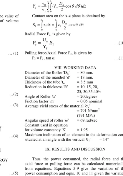
VIII. WORKING DATA Diameter of the Roller 'DR' = 80 mm.
Diameter of the mandrel 'd' = 18 mm. Thickness of the tube 'to' = 3.5 mm
Reduction in thickness 'R' = 10, 15, 20, 25, 30,35,40%
Angle of Roller ’α’ = 20degrees
Friction factor 'm' = 0.05 nominal Average yield stress ofthe material ’σy'
= 791 N/mm2 (791 MPa)
Angular speed of roller ’ω’ = 69 rad/sec
Constant used in equation
for volume constancy 'K' = 1.95
Maximum inclination of an element in the deformation zone
situated at an angle with the vertical ’θ1' = 14°
IX. RESULTS AND DISCUSSION
Thus, the power consumed, the radial force and the axial force or pulling force can be calculated numerically from equations. Equations 5-9 give the variation of the power consumption and eqns. 10 and 11 given the variation of forces with various process variables. The effect of variation in the different process variables is shown in graph of Figs. 3-11.
A. Variation in Power and Forces with respect to the variation in %age reduction.
It can be noted that the power consumption increases with the increase in the percentage reduction. It is quite obvious that as the thickness of the work piece increases i.e. volume of the material deformed increases more power is required for deformation and also to push the material over the mandrel. 0 10000 20000 30000 40000 50000 60000 70000
10 15 20 25 30 35 40
Reduction (%) R
P o w e r U e (N m /s e c ) m=0.05 to = 3.5
DR = 80
a = 20°
It can be seen that with the increase in percentage reduction in wall thickness the radial and axial force also increases. It is obvious as the volume of the deformed materials increases necessitating more force to push the deformed material.
0 500 1000 1500 2000 2500 3000 3500
10 15 20 25 30 35 40 Reduction (%) R
R
a
d
ia
l
F
o
rc
e
P
r(
N
e
w
to
n
)
m=0.05
to = 3.5
DR = 80
a = 20°
Fig. 4 : Relationship between Pr and R
0 200 400 600 800 1000 1200 1400
10 15 20 25 30 35 40 Reduction (%) R
A
x
ia
l
F
o
rc
e
P
z
(N
e
w
to
n
)
m=0.05
to = 3.5
DR = 80
a = 20°
Fig. 5 : Relationship between PZ and R
B. When the roller flattens and roller is not assumed to be rigid
In the previous analysis, the roller is assumed to be rigid. However, the rolls will deform elastically to an appreciable extent, and allowance must be made for this. A sufficiently accurate correction is obtained by supposing that the rolls, flatten to some greater diameter DR'. The changed
diameter may be approximated as per DR' = 1.1 DR. Rowe
(2000).
DR' = 1.1 DR = 1.1x80 = 88 mm
D
R
80
mm
DR=80
0 10000 20000 30000 40000 50000 60000 70000 80000
10 15 20 25 30 35 40
Reduction(%)R
t0 = 3.5
α = 20º m = 0.05
P
o
w
e
r
U
e
(N
m
/s
e
c
)
DR´=88
Fig. 6 : Total Energy vs. %age Reduction at different roller Diameter
0 500 1000 1500 2000 2500 3000 3500 4000 4500
10 15 20 25 30 35 40
Reduction(%)R
R
a
d
ia
l
F
o
r
c
e
P
r
(N
e
w
to
n
)
t0 = 3.5
α = 20º m = 0.05
DR=80 DR´=88
Fig. 7 : Pr vs. %age reduction at different roller diameter
0 200 400 600 800 1000 1200 1400 1600
10 15 20 25 30 35 40
Reduction(%)R
A
x
i
a
l
F
o
r
c
e
P
z
(
N
e
w
t
o
n
) t
0 = 3.5
α = 20º m = 0.05
DR=80 DR´=88
Fig. 8 : Pz vs. %age of reduction at different roller diameter
In the graphs plotted between Total energy, radial force and axial force vs. %age reduction it can be seen that power consumption, axial force and radial force increases as the diameter of the rollers increases due to flattening. This may be because of the fact, as the diameter of the roller increases due to flattening, the area of contact between the roller and the work piece increases which necessitates more power and larger forces to cause the plastic flow in the material.
C. Comparison with Singhal (1990) and Hayama and Kudo (1979 I, II)
In the graphs comparison has been made with the work carried out Singhal (1990) and Hayama and Kudo (1979 I, II). In his work on hard-to-work materials Singhal has taken value of Average yield stress as 43.8 kg/mm2 (430 MPa) but he has no where mentioned how it has been calculated. Hayama and Kudo has worked experimentally on soft materials with average yield stress 23 kg/mm2 (226 MPa).
In the case of present author the average yield stress for Titanium (one of the hard-to-work materials) has been calculated as 791 MPa. These figures show comparison of total energy, axial force and radial force verses reduction. The trend of the graphs is similar i.e. total energy, axial force and radial force increases with increase in percentage
reduction. But the value are higher in the case of σ = 791 MPa followed by σ = 430 MPa and σ = 226 MPa. It shows
that more energy forces are required in the case of working on hard materials.
0 1 0 0 0 0 2 0 0 0 0 3 0 0 0 0 4 0 0 0 0 5 0 0 0 0 6 0 0 0 0 7 0 0 0 0
1 0 1 5 2 0 2 5 3 0 3 5 4 0
s ig m a = 7 9 1 s ig m a = 4 3 0 s ig m a = 2 2 6
0 1 0 0 0 0 2 0 0 0 0 3 0 0 0 0 4 0 0 0 0 5 0 0 0 0 6 0 0 0 0 7 0 0 0 0
1 0 1 5 2 0 2 5 3 0 3 5 4 0
R e d u c tio n (% )R
s ig m a = 7 9 1 s ig m a = 4 3 0 s ig m a = 2 2 6
P
o
w
e
r
U
e
(N
m
/s
e
c
)
t0 = 3 .5
α = 2 0 °
m = 0 .0 5
DR= 8 0
0 500 1000 1500 2000 2500 3000 3500
10 15 20 25 30 35 40
Reduction(%R)
R
a
d
ia
l
F
o
rc
e
P
r(
N
e
w
to
n
)
Sigma=791 Sigma=430 Sigma=226
t0 = 3.5
α = 20° m = 0.05 DR=80
Fig. 10 : Comparison of relationship between Pr and %age reduction for same value of m
0 200 400 600 800 1000 1200 1400
10 15 20 25 30 35 40
Reduction(%)R
A
x
ia
l
F
o
rc
e
P
z
(N
e
w
to
n
)
sigma=791 sigma=430 sigma=226
t0 = 3.5
α = 20°
m = 0.05
DR=80
Fig. 11 : Comparison of relationship between Pz and %age
reduction for same value of m
X. CONCLUSIONS
1. The working range in case of hard-to-work materials is less. Improvement in the ductility of the titanium one of the hard-to-work materials has been calculated under plane strain condition and it has improved by about 15% because of the presence of hydrostatic stress in conformity to the Birdgeman Law.
2. Equation of continuity which stands for volume constancy has been satisfied. The value of K has been calculated which is applied in the analysis of velocity equations.
3. Constitutive equation for Titanium, one of the hard-to-work material has been developed and value of average yield stress of the material has been calculated to be 791 MPa.
4. The three rollers which are mounted on the chuck make an epicyclic train. The angular speed of rollers has been calculated as 69 rad/sec.
5. From Fig. 4, 5, 6, it is clear that with increase in %age reduction there is increase in power consumption, radial force and axial force.
6. From Fig. 7, 8, 9 it is clear as the roller flattens, then diameter of the roller increases and consequently there is increase in power consumption, axial force and the radial force. This may be due to the fact that as the diameter of the roller increases, more volume of the
material comes into contact due to which more power and forces are required.
7. Singhal (1990) has taken the value of yield stress 430 MPa which is near to the average value of yield stress for soft materials taken by Hayama and Kudo (1979 I, II) as 226 MPa. Whereas the present author has calculated this value of average yield stress for hard-to-work material as 791 MPa. The comparison has been made for these values of average yield stress vs. % age reduction in Fig. 10, 11, 12. The trend of the graphs is similar but the value for total energy, axial force and radial force are higher in the case of average yield stress 791 Mpa. Thus it becomes obvious that in the case of hard materials more energy, axial force and radial force is required as compared to soft materials.
REFERENCES
[1] Avitzur, B. (1977); Metal forming process and analysis, Tata
McGraw Hill Publishing Company Limited, New Delhi.
[2] Hayama, M. and Kudo, H. (1979 I); Experimental study of tube
spinning, JSME, 22(167), pp. 769-775.
[3] Hayama, M. and Kudo, H. (1979 II); Analysis of diametral growth
and working forces, Bull. JSME, 22 (167), pp. 776-784.
[4] Johnson, W. and Mellor, P.B. (1962); Plasticity for mechanical
engineers. D. Van Nostrand Company Ltd., London.
[5] Metals Hand Book (1975); Volume 1, 8th
Edn., American Society for Metals, Metals Park, Ohio-44073, USA.
[6] Prakash, Rajnish and Singhal, R.P. (1995); Shear spinning technology
for manufacture of long thin wall tubes of small bore, Journal of Materials Processing Technology, 54, pp. 186-192.
[7] Rowe, G.W. (2000); Principles of industrial metalworking process,
CBS Publishers and Distributors, New Delhi.
[8] Singhal, R.P. and Prakash, Rajnish (1990); An experimental study of
shear spinning of tube of hard-to-work materials, Advanced Technology of Plasticity, Vol. 2, pp. 853-857.
[9] Singhal, R.P., Das, S.R. and Prakash, Rajnish (1987); Some
experimental observations in the shear spinning of long tubes, Journal of Mechanical Working Technology, 14, pp. 149-157.
[10] Singhal, R.P., Saxena, P.K. and Prakash, Rajnish (1990); Estimation of power in the shear spinning of long tubes in hard-to-work materials, Journal of Material Processing Technology, Elsevier, 23, pp. 29-40.
[11] Quigley, E. and Monaghan, J. (2000); Metal forming : An analysis of spinning process, Journal of Materials Processing Technology, 103(1), pp. 114-119.
[12] Gotoh, M. and Yamashita, M. (2001); "A study of high-rate shearing of commercially pure aluminium sheet", Journal of Materials Processing Technology, pp. 253-264.
[13] Levy, B.S., Van Tyne, C.J. and Stringfield, J.M. (2004); Characterizing steel tube for hydroforming applications, Journal of Materials Processing Technology, pp. 280-289.
[14] Jansson, M., Nilsson, L. and Simonsson, K. (2007); On process parameter estimation for the tube hydroforming process, Journal of Materials Processing Technology, pp. 1-11.
[15] Bortot, P., Ceretti, E. and Giardini, C. (2008); The determination of flow stress of tubular material for hydroforming applications, Journal of Materials Processing Technology, pp. 381-388.