Journal homepage:www.ijaamm.com
International Journal of Advances in Applied Mathematics and Mechanics
Frictionless contact of a rigid punch indenting a transversely isotropic
elastic layer
Research Article
Rajesh Patraa, S. P. Barikb,∗, P. K. Chaudhuric
aDepartment of Mathematics, Hooghly Engineering & Technology College, Vivekananda Road, Hooghly-712103, India bDepartment of Mathematics, Gobardanga Hindu College, 24-Parganas (N),Pin-743273, India
cRetired Professor, Department of Applied Mathematics, University of Calcutta, 92, A. P. C. Road, Kolkata-700009, India
Received 22 January 2016; accepted (in revised version) 09 February 2016
Abstract: This article is concerned with the study of frictionless contact between a rigid punch and a transversely isotropic elastic layer. The rigid punch is assumed to be axially symmetric and is being pressed towards the layer by an applied concentrated load. The layer is resting on a rigid base and is assumed to be sufficiently thick in comparison with the amount of indentation by the rigid punch. The relationship between the applied loadPand the contact area is obtained by solving the mathematically formulated problem through use of Hankel transform of different order. Effect of indentation on the distribution of normal stress at the surface as well as the relationship between the applied load and the area of contact have been shown graphically.
MSC: 74E10• 74R20
Keywords:Transversely isotropic medium • Integral transform • Contact problem • Alamnsi’s theorem • Fredhlom integral equation
© 2016 The Author(s). This is an open access article under the CC BY-NC-ND license(https://creativecommons.org/licenses/by-nc-nd/3.0/).
1. Introduction
When two deformable solids are in contact and external load is applied to press one onto the other deforma-tion occurs in the solids which may cause some changes in the contact area.There are obviously some reladeforma-tionships between the applied load and the contact area. The distribution of stresses in either body in and outside the contact area are subject to change significantly depending upon the nature of applied load.The determination of the stresses in and outside the contact area as well as the relationship between the applied load and contact area is the subject of study in solid mechanics for long which started through the initial investigation of Hertz[1]. With the application of load, contact area may or may not vary; accordingly contact problems have been classified as advancing (increase of contact area), receding (decrease of contact area) and stationary (contact area remaining the same). Another aspect of consideration in the study of contact problems is the frictional force at the surface of contact.Since contact is the principal method of applying loads to a deformable body, study of contact problems in various kinds of deformable media is important as well as necessary. Owing to their applications in a great variety of structural systems, such as foundations, pavements in roads and runways, automotive disk brake systems and many other technological applica-tions, considerable progress has been made with the analysis of contact problems in solid mechanics. Among several works done, we may mention a few: Shvets et al. [2], Chaudhuri and Ray [3,4], Comez, et al. [5], Barik et al. [6,7], Gecit [8], Selvanduari [9], Fabrikant [10]. Various types of contact problems are discussed in books and journals, e.g. Johnson [11], Gladwell [12], Hills et al. [13], Raous et al. [14] and Rogowski[15], Chen [16] etc.
∗ Corresponding author.
The present investigation aims to find the elastostatic solution of an axially symmetric frictionless contact be-tween a transversely isotropic layer and a rigid cylindrical, spherical and conical indenters which are loaded by a concentrated force P. Using the operator theory, we derive a general solution that is expressed in terms of the three potentials. These functions satisfy differential equations of the second order and are quasi-harmonic functions. Mak-ing use of these fundamental solutions, the punch problem in the aforesaid three cases,is investigated. The solution of the problem has been reduced to the solution of one Fredhlom type integral equation of second kind which re-quires numerical treatment. The numerical results are discussed and presented graphically to show the influence of indentation in the layer on various states of interest.
2. Formulation of the problem
We consider an elastic layer of transversely isotropic material and of thicknessHlying on a rigid base.On the free surface of the layer, a rigid punch of axisymmetric character is placed with its axis of symmetry normal to the free surface of the layer. We also assume that the punch is pressed towards the layer by an applied concentrated force of magnitudeP. Cylindrical coordinate system (r,θ,z) withz−axis along the inward drawn normal to the free surface of the layer, will be used to specify the position of a point in the layer. We shall make the following assumptions in our discussion:
(a) the axis of symmetry of the transversely isotropic material is along thez-axis
(b) there is no force of gravity
(c) linear theory of elasticity holds
(d) the thickness of the layer is sufficiently large in comparison to the indented depth of the punch.
Because of axisymmetric structure of the indentor, the displacement vectoruwill have its cross radial compo-nentuθ=0 i.e.u=(ur, 0,uz) and all the physical quantities are independent ofθ. The solution of frictionless contact
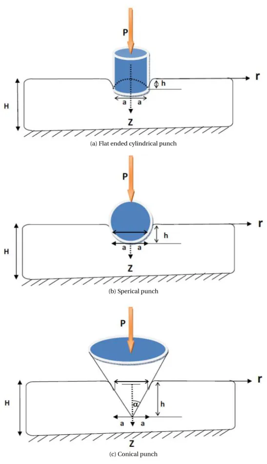
problem demands the relationship between the applied load and the contact area. The geometry of the problem is shown inFig. 1.
The mathematical formulation of the problem consists of
Equilibrium equations:
C11L1ur+C44D2ur+(C13+C44)D∂uz∂r =0
C44L0uz+C33D2uz+(C13+C44)D∂[r∂rr ur]=0
)
(1)
where Lk= ∂
2
∂r2+
1 r
∂ ∂r−
k
r2 k=0, 1 D=
∂ ∂z
The boundary conditions:
uz(r, 0)=f(r), 0≤r≤a (2)
uz(r,H)=0, r≥0 (3)
σr z(r, 0)=0, r≥0 (4)
σzz(r, 0)=0, r>a (5)
σr z(r,H)=0, r≥0 (6)
The parametersCi jappearing in (1) are the elastic coefficients. In addition to the boundary conditions, the
dis-placement components should satisfy the regularity conditionur,uz→0 as p
r2+z2→ ∞. At the surface of contact
of the material with the indenter 0≤r≤a, the boundary condition will depend upon the shape of the indenter. Ifhis the indented depth of the solid into the material then
(a) for a cylindrical indenter the condition will be
uz(r, 0)=f(r)=h (7)
(b) for a conical indenter havingαas the semi-vertical angle, the condition is
uz(r, 0)=f(r)=h−(a−r) cotα (8)
(c) for a spherical indenter having radiusR, the condition is
uz(r, 0)=f(r)=h−r
2
(a) Flat ended cylindrical punch
(b) Sperical punch
(c) Conical punch
3. Method of solution
Solution of partial differential Eq. (1) requires use of Hankel transform technique of different order. We shall outline the method adopted by Dyka and Rogowski [17] for the first part of discussion and thereafter apply those results in our considered problem.
Let us write
c
ur(ξ,z)=H1[ur(r,z);r→ξ]=R0∞ur(r,z)r J1(rξ)d r
c
uz(ξ,z)=H0[uz(r,z);r→ξ]=R0∞{uz(r,z)}r J0(rξ)d r
(10)
whereJ0andJ1are the Bessel functions of the first kind and of order zero or one, respectively, andξis the transform
parameter. We use the following properties of Hankel transforms
Hν[Lνf(r,z);r→ξ]= −ξ2fbν(ξ,z)
H1[∂f∂r(r,z);r→ξ]= −ξfb0(ξ,z)
H0[∂[r fr∂r(r,z)];r→ξ]=ξfb1(ξ,z)
(11)
Applying the Hankel transformations (10) to the Eq. (1) we get a coupled ordinary differential equations, which may be written in the form
A · b ur b uz ¸ = · 0 0 ¸ (12)
whereAis the following operator matrix
A=
·
−C11ξ2+C44D2 −ξ(C13+C44)D
ξ(C13+C44)D −C44ξ2+C33D2
¸
(13)
We have
|A| = −a0(D2−λ21ξ2)(D2−λ22ξ2) (14)
whereλ2i(i=1, 2) are the roots of the following cubic algebraic equation
a0λ4+b0λ2+c0=0 (15)
with the coefficients defined by
a0= −C33C44
b0=C11C33−2C13C44−C132
c0= −C11C44
(16)
Using the operator theory, we obtain the general solution to the Eq. (12), as
b
ur(ξ,z)=Ai1Fb(ξ,z)
b
uz(ξ,z)=Ai2Fb(ξ,z)
¾
(17)
where Ai j are the algebraic cominors of the matrix operator andFb(ξ,z) is the zero order Hankel transform of the
general solutionF(r,z), satisfying the equations
|A|F(bξ,z)=0
(D2+λ21∆)(D2+λ22∆)F(r,z)=0
(18)
Here∆= ∂
2
∂r2+
1 r
∂ ∂r andD
2
= ∂
2
∂z2.
Takingi=3 and writing down the expression forA3j, we obtain
b
ur(ξ,z)=(C13+C44)ξDFb(ξ,z)
b
uz(ξ,z)=(−C11ξ2+C44D2)Fb(ξ,z)
¾
(19)
Using the inverse Hankel transforms to Eq. (19), the original solution for the displacement components are obtained as:
ur(r,z)= −(C13+C44) ∂
2 ∂r∂zF(r,z)
uz(r,z)=(C11∆+C44D2)F(r,z)
¾
Using the generalized Almansi’s theorem [18], the functionF(r,z), which satisfies Eq. (18)2, can be expressed in terms
of three quasi-harmonic functions
F=
½
F1+F2 for distinctλi
F1+zF2 forλ1=λ2 (21)
whereFi(r,z) satisfies, respectively
(∆+ 1 λ2iD
2
)Fi(r,z)=0 i=1, 2 (22)
As we shall see later that the roots of Eq. (15) are all distinct in our considered problem, so we shall consider only first solution in Eq. (21).
Using
∆Fi= −
1 λ2iD
2F
i (23)
and summing in Eq. (20), we obtain
ur(r,z)= −P2i=1(C13+C44)∂
2F i ∂r∂z
uz(r,z)= −P2i=1(C44−Cλ112 i
)∂2Fi ∂z2 (24)
Introducing functionsFi(r,z) such that
∂
∂zFi(r,z)= − 1 λi
ϕi(r,z) (25)
Eq. (24) can be expressed as
ur(r,z)=P2i=1aλii1∂ϕi∂r
uz(r,z)=P2i=1aλii2∂ϕ∂zi (26) where
ai1=C13+C44
ai2=C44−Cλ112 i (27)
The quasi-harmonic functionϕi(r,z) satisfies the equation ³
∆+λ12 i
∂2 ∂z2
´
ϕi(r,z)=0 (28)
The relationships between stress, displacement for a transversely isotropic elastic medium in the case of axial sym-metry, are
σr r(r,z)=C11∂ur∂r +C12urr +C13∂uz∂z
σθθ(r,z)=C12∂ur∂r +C11urr +C13∂uz∂z
σzz(r,z)=C13∂u∂rr +C13urr +C33∂u∂zz
σzr(r,z)=C44(∂ur∂z +∂uz∂r )
(29)
Substituting Eq. (24) into Eq. (29), we obtain
σr r(r,z)= −P2i=1
ai3 λi
∂2ϕi
∂z2 −(C11−C12)urr σzz(r,z)=P2i=1
ai4 λi
∂2ϕi ∂z2
σθθ(r,z)= −P2i=1
ai3 λi
∂2ϕi
∂z2 −(C11−C12)∂ur∂r σzr(r,z)=P2i=1
ai5 λi
where
ai3=
2C11C13+C11C44−C13C44λ2i λ2i
ai4=−
C2
13−C13C44−C11C33+C33C44λ2i λ2
i
ai5=
(2C244+C13C44)λ2i−C11C44 λ2 i (31)
It can be easily verified that:
the equilibrium equations for stresses (Nowacki [19])
∂σr r ∂r +
∂σr z ∂z +
σr r−σθθ r =0
∂σzr ∂r +
∂σzz ∂z +
σzr r =0
(32) are satisfied.
For axially symmetric problems, the general solution of the differential Eq. (28) may be written as
ϕi(r,z)= Z∞
0 [Ai(ξ)e
−λiξz+B
i(ξ)eλiξz]J0(rξ)dξ (33)
whereAi(ξ),Bi(ξ)(i=1, 2) are arbitrary functions of the transform parameterξ, which are to be determined from the
boundary conditions (2)-(6) andλi are the roots of Eq. (15).
Using Eqs. (33), (26) and (30) into the boundary conditions (2)-(6) we obtain
2
X
i=1
ai5[Ai(ξ)−Bi(ξ)]=0, r≥0 (34)
2
X
i=1
ai5[Ai(ξ)e−λiξH−Bi(ξ)eλiξH]=0, r≥0 (35)
2
X
i=1
[Ai(ξ)e−λiξH−Bi(ξ)eλiξH]=0, r≥0 (36)
2
X
i=1
Z∞
0 [−Ai(ξ)+Bi(ξ)]ξJ0(rξ)dξ=f(r), 0≤r≤a (37)
2
X
i=1
Z∞
0
ai4
λi
[Ai(ξ)+Bi(ξ)]ξ2J0(rξ)dξ=0 r>a (38)
Eqs. (35)-(36), yield
Bi(ξ)=Ai(ξ)e−2λiξH (i=1, 2) (39)
and
A1(ξ)=χ1(ξ)A2(ξ) (40)
where
χ1(ξ)= −
a25
a15
(1−e−2λ2ξH)
(1−e−2λ1ξH) (41)
Using Eq. (39) in Eq. (37) and Eq. (38) we get, respectively,
Z∞
0 [−(1−e
−2λ1ξH)χ
Z∞
0
χ2(ξ)A2(ξ)ξ2J0(rξ)dξ=0, r>a (43)
where
χ2(ξ)=
a14
λ1
(1+e−2λ1ξH)χ1(ξ)+
a24
λ2
(1+e−2λ2ξH) (44)
Now we assume that
χ2(ξ)A2(ξ)ξ=
r
2 π
Za
0
ϕ1(x)cos(ξx)d x (45)
Then Eq. (43) is automatically satisfied. Solving Eqs. (40) and (45) we get
A1(ξ)=
χ1(ξ)
χ2(ξ)ξ
r
2 π
Za
0 ϕ1(x)cos(ξx)d x (46)
and
A2(ξ)=
1 χ2(ξ)ξ
r
2 π
Za
0 ϕ1(x)cos(ξx)d x (47)
From Eqs. (42) and (47) we get
Za
0
ϕ1(x)k11(r,x)d x=f(r), 0≤r≤a (48)
where
k11(r,x)=
Z∞
0
G(ξ)J0(ξr)cos(ξx)dξ, (49)
G(ξ)=
r
2 π
1 χ2(ξ)
[−(1−e−2λ1ξH)χ1(ξ)−(1−e−2λ2ξH)] (50)
Now Eq. (48) can be written as
Zr
0
d x p
x2−r2[ϕ1(x)+
Za
0 ϕ1(u)L(u,x)d u]=f(r) (51)
which is a Abel type integral equation. After some working we get the integral equation inϕ1as
ϕ1(x)+
Za
0 ϕ1(u)L(u,x)d u=
2
πg(x), 0≤x≤a (52)
where
g(x)=d xd Rx
0
r f(r)
p
x2−r2d r = h, for cylindrical indentor
= h+(π2x−a) cotα, for conical indentor
= h−xR2 for spherical indentor
(53)
L(u,x)=2
π
Z∞
0 Ω
(ξ)cos(ξu)cos(ξx)dξ (54)
Ω(ξ)=G(ξ)−1 (55)
Before further proceeding it will be convenient to introduce non-dimensional variablesu′,x′andr′by rescaling by length scalea:
u′=u
a,x
′=x
a,r
′=r
For notational convenience, we shall use only dimensionless variables and shall ignore the dashes on the transformed variables and the integral Eq. (52) becomes
ϕ1(x)+
Z1
0 ϕ1(u)L(u,x)d u=
2
πg(x), 0≤x≤1 (57)
This equation determines the functionϕ1.
Now equilibrium condition demands
P+
Za∗
0 2πr d rσzz(r, 0)=0
⇒P+2π
Z∞
0 M(ω)[
Za∗
0 J0(ωr)r d r]dω=0 (58)
where
M(ω)=
r
2
πω[{β1(ω)+β2(ω)}
Z1
0 ϕ1(x)cos(ωx)d x] (59)
β1(ω)=
a14λ1χ1(ω)
χ2(ω)
(1+e−2λ1ω), β2(ω)=
a24λ2
χ2(ω)
(1+e−2λ2ω) and a∗=a
h,ω=ξh.
The Eq. (58) is the relationship between the applied loadPand the radius of the contact area.
4. Numerical results and discussions:
The present study aims at investigating a frictionless contact problem in a finite transversely isotropic elastic layer. The main objective of the present discussion is to study the effects of indentation on the load contact area relationship as well as normal stress distribution. Numerical evaluation requires numerical solution of the integral equation Eq. (52).
In our present discussion we have considered the transversely isotropic material as Cobalt, Magnesium and Titanium to illustrate theoretical results. The numerical values of the elastic coefficients for the materials are listed in
Table 1[20].
Table 1.Basic data for three transversely isotropic materials.
Quantity Unit Cobalt Titanium Magnesium
C11 GPa 307.0 162.4 59.7
C33 GPa 358.1 180.7 61.7
C44 GPa 78.3 46.7 16.4
C12 GPa 165.0 92.0 26.2
C13 GPa 103.0 69.0 21.7
Our numerical study will cover three different types of rigid indenter, namely, cylindrical shaped, spherical shaped and conical shaped.
Fig. 2relate results for cylindrical punch,Fig. 3relate results for spherical punch, whileFig. 4relate results for conical punch. Fig. 2(a)shows effect of indentationh onσzz(r, 0) for flat-ended cylindrical punch for various
values ofhin a transversely isotropic medium like titanium. As expected, more indentation will require more normal stress. Fig. 2(b)shows variation ofσzz(r, 0) for three different materials with fixed indentationh of the flat-ended
cylindrical punch.It is evident fromFig. 2(b)that increase in rigidity will generate less normal stress. There are not much significant changes in the behaviour of the stresses in the case of spherical indenter from the corresponding results of cylindrical punch as shown inFig. 3. But here we see that the values ofσzz(r, 0)→0 asr→1. In the case of
conical punch some kind of dissimilarities from the above two punches are observed. Firstly, in this case the stresses act oppositely and have decreasing numerical values with increasingh. This is shown inFig. 4(a). Fig. 4(b)shows a comparison between results of three materials for fixedh. The results are similar to those inFig. 2(b). Variations of normal stress withr have been also studied with different shapes of the conical punch by varying the semi-vertical angle. Results are shown inFig. 4(c).
Fig. 5show the variation of the applied loadP with contact radius a
(a)
(b)
Fig. 2.(a) Effect of indentationhonσzz(r, 0) for flat ended cylindrical punch (Titanium) (b) Variation ofσzz(r, 0) for various material with fixed indentation of the flat ended cylindrical punch (h=0.1)
(a) (b)
(a)
(b)
(c)
(a)
(b)
(c)
References
[1] H. Hertz, On the contact of rigid elastic solids, J. reine und angewandte Mathematik 92 (1882) 156-171.
[2] R.M. Shvets, R.M. Martynyak, A.A. Kryshtofovych, Discontinuous contact of an anisotropic half-plane and a rigid base with disturbed surface, Int. J. Eng. Sci.34 (1996) 183-200.
[3] P.K. Chaudhuri, S. Ray, Receding axisymmetric contact between a transversely isotropic layer and a transversely isotropic half-space, Bull. cal. Math. Soc. 95 (2003) 151-164.
[4] P.K. Chaudhuri, S. Ray, Receding contact between an orthotropic layer and an orthotropic half-space,Archives of mechanics 50 (1998) 743-755.
[5] I. Comez, A. Birinci, R. Erdol, Double receding contact problem for a rigid stamp and two elastic layers,Europian Journal of mechanics A/solids 23 (2004) 909-924.
[6] S.P.Barik, M. Kanoria, P.K. Chaudhuri, Contact problem for an anisotropic elastic layer lying on an anisotropic elastic foundation under gravity, J. Indian Acad. Math.28 (2006) 205-223.
[7] S.P. Barik, M. Kanoria, P.K. Chaudhuri, Effect of nonhogeniety on the contact of an isotropic half-space and a rigid base with an axially symmetric reces, Journal Of Mechanics Of Materials and Structures 3 (2008) 1-18.
[8] M.R. Gecit, Axisymmetric contact problem for an elastic layer and an elastic foundation,Int. J. Eng. Sci. 19 (1981) 747-755.
[9] A.P.S. Selvanduri, The body force inducing separation at a frictionless precompressed transversely isotropic in-terface, T. Can. Soc. Mech. Eng. 7 (1983) 154-157.
[10] V.I. Fabrikant, Elementary solution of contact problems for a transversely isotropic layer bonded to a rigid foun-dation, Z. angew. Math. Phys. 57 (2006) 464-490.
[11] K.L. Johnson, Contact Mechanics, Cambridge University Press, Cambridge, 1985.
[12] M.L. Gladwell, Contact Problems in the Classical Theory of Elasticity, Sijthoff and Noordhoff, The Netherlands, 1980.
[13] D.A. Hills, D. Nowell, A. Sackfield, Mechanics of Elastic Contacts, Butterworth-Heinemann, 1993. [14] M. Raous, M. Jean, J.J. Moreau, Contact Mechanics, New York, Plenum Press, 1995.
[15] B. Rogowski, Contact Problems for Elastic Anisotropic Media-A series of Monographs, Technical University of Lodz, 2006.
[16] W.Q. Chen, On piezoelastic contact problem for a smooth punch, Int. J. Solids Struct. 37 (2000) 2331-2340. [17] E. Dyka, B. Rogowski, On the contact problem for a smooth punch in piezoelectroelasticity, Journal of Theoritical
and Applied Mechanics, Warsaw 43 (2005) 745-761.
[18] M.Z. Wang, X.S. Xu, A generalization of Alamnsi’s theorem and its application,Appl. Math. Modelling 14 (1990) 275-279.
[19] W. Nowacki, Teoria Spre¸˙zysto´sci. PWN, Warszawa, 1973. [20] L.B. Freund, S.Suresh, Thin Film Materials, CUP, 2003.
Submit your manuscript to IJAAMM and benefit from:
◮ Regorous peer review
◮ Immediate publication on acceptance
◮ Open access: Articles freely available online
◮ High visibility within the field
◮ Retaining the copyright to your article