!" # $ " %
& ' ()*+) , +)&-&#..) /+) )0) / /1 )(0) #
Department of ECE, K L University, Guntur DT, AP, India *Corresponding Author: [email protected]
Coplanar waveguide fed circularly polarized microstrip patch antenna performance evaluation is presented in this paper. The broadband characteristics are attained by placing open end slot at the lower side of the antenna. The proposed design has the return loss of less than )10dB and VSWR<2 in the desired band of operation. A gain of 3dB to 4dB is attained in the desired band with good radiation characteristics and a suitable axial ratio of less than 3 dB is attained in the prescribed band of operation. Proposed antenna is fabricated on the FR4 substrate with dielectric constant of 4.4. Parametric analysis with change in substrate permittivity also performed and the optimized dimensions are presented in this work.
Keywords: Circular polarization, Slotted aperture, Broadband, Coplanar waveguide, Axial ratio, Half power beam width, Impedance bandwidth.
2
G Gap between feed line and ground plane
h Height of the substrate, mm L1 Length of the patch element, mm
L2 Length of left side ground plane to feed line, mm L3 Length of right side ground plane to feed line, mm L4 Length of the feed line, mm
L5 Length of patch plus feed line, mm L6 Length of the slot on the ground plane, mm Ls Substrate length, mm
W Width of the feed line, mm Ws Width of the substrate, mm W1 Width of the patch element, mm W2 Width of the left plane ground, mm W3 Width of the right plane ground, mm W4 Width of the ground plane slot, mm
Greek Symbols
εeff Effective dielectric constant
εr Dielectric constant
AR Axial Ratio
CP Circular Polarization
CPW Coplanar Waveguide Feeding HPBW Half Power Beam Width VSWR Voltage Standing Wave ratio
Axial ratio bandwidth can be improved by using different techniques. By implanting a pair of grounded strips or three inverted L)Shaped grounded strips, the axial ratio bandwidth can be improved [6)9].
In this paper structurally simple circularly polarized antenna model is proposed. Asymmetric perturbation is introduced by placing a slot on the lower side of the design. The current antenna is fed by a wide tuning stub can provide circular polarization and impedance bandwidth.
5
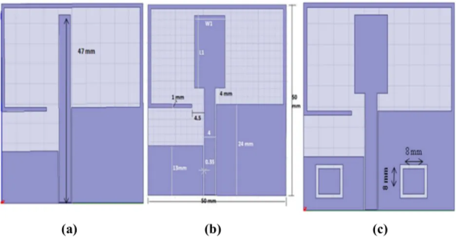
It is obvious that the change in ground plane would sensitively influence the performance of Circular Polarization operation [10)11]. A wide tuning stub with length L1 and width W1 is used to improve the circular polarization. If open slot is taken at lower right side of the feeding line then circular polarized waves of opposite sense will be produced. In order for the AR bandwidth enhancement, a wide tuning stub is used in the model as shown in the Fig 1.
! "
#
Figure 1 shows the proposed coplanar waveguide fed circularly polarized slot antennas of 50 ohm CPW feeding with signal strip and gaps have the width of 4 and 0.35 mm. The first model is a slotted broadband monopole with strip length of 47 mm and the second model is the slotted rectangular broadband monopole with wider tuning stub. For wider impedance bandwidth and axial ratio bandwidth, an asymmetric ground plane is used in this design. The third model is the modified model of 2 with slots on the ground plane on either side to the feed line. The length of the feed line is tuned for good circular polarization bandwidth. Figure 2 shows the fabricated prototype of proposed model. Figure 3 shows the simulated return loss Vs frequency characteristics of the three models. It is been observed from the results that an impedance bandwidth of 70% (2.4)5 GHz) from the first model, impedance bandwidth of 100% (2.4)7.2 GHz) from second model and 102% from the third model is attained. Figure 4 shows the measured and simulation return loss of proposed model 3. Simulation and measurement results are in good agreement with each other.
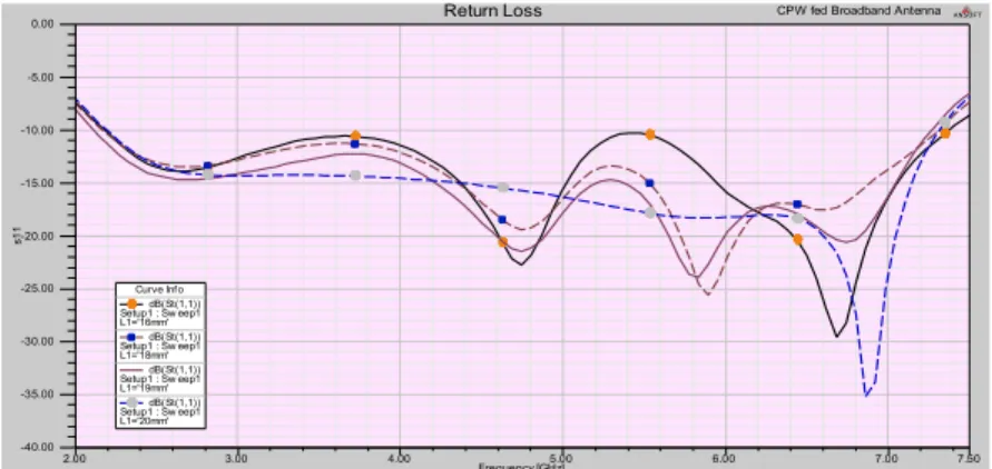
frequency band. Figure 6 shows the axial ratio curve with change in L1. Impedance bandwidth of 21.3% from L1=16 mm, 34.2% from L1=18 mm, 31.6% from L1=19 mm and 40% from L1=20 mm attained from this result.
$
! %
' " % ( ) * + ,
-* . % ( ) * + ,
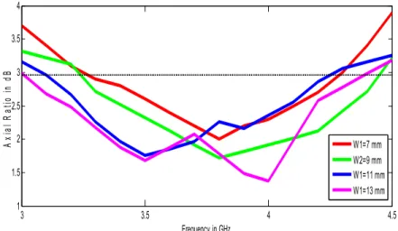
-Figure 7 shows the reflection coefficient of the antenna with change in slot width W1. Maximum bandwidth of 5400 MHz from W1=9 mm and minimum of 5000 MHz from W1=11 mm is attained from the current study result. Figure 8 shows the axial ratio curve with change in width of the slot W1 and an impedance bandwidth of 35% is attained for the case of W1=13 mm.
/ 0 1 % 2 )/ , !
6 7 8 8
39 :;+<= 7 68 6 8 8 8 "
>'? & 4 ) %
0 % . ""
> $ -&% % @ AB @ . CDEED
&% % @ AB @ . CD 2EED
&% % @ AB @ . CD 5EED
&% % @ AB @ . CDEED
6 6 8 7 7 8
8 8 6 6 8 7
3 9 ;+<
)
F
0
%
&
. C EE . C 2 EE . C 5 EE . C EE
6 7 8 8
39 :;+<= 68 6 8 8 8 "
>'? & 4 ) %
0 % . ""
>$ -&% % @ AB @ ? CD EED
&% % @ AB @ ? CD5EED
&% % @ AB @ ? CDEED
+ . % 2 )/ , !
Figure 9 shows the reflection coefficient with change in thickness of the substrate material. Generally 1.6 mm thickness FR4 material is widely available, but the result shows the superior performance for 0.8 mm thickness, so we fabricated the model on 0.8 mm thickness FR4 material, which gives impedance bandwidth of 88% in the frequency range 2)7.25 GHz with centre frequency of 4.625 GHz. Figure 10 shows the parametric analysis for reflection coefficient with change in width of the ground plane slot. The simulation result shows that with the optimized dimension of 8 mm, the antenna is resonating in the wide band. Figure 11 shows the axial ratio of the proposed model with change in width of the ground plane slot.
, 0 % % 3)- + & *
6 6 8 7 7 8
8 8 6 6 8 7
3 9 ;+<
)
F
0
%
&
? C EE ? C5 EE ? C EE ? C 6 EE
6 7 8 8
3 9 :;+<= 68 6 8 8 8 "
>'? & 4 ) %
0 % . ""
> $ -& %
% @ A B @
" 4+CD 2EED & %
% @ A B @
" 4+CD EED & %
% @ A B @
" 4+CD 7EED & %
% @ A B @
6
- 0 1 %
+ + ' ,
. 1 % + + ' ,
%
! 435
6 7 8 8
3 9 :;+<= 78
68 8 8 8
"
>'? & 4 ) %
0 % . ""
> $ -& %
% @ A B @
" CD EED "B CD2EED & %
% @ A B @
" CD 8EED "B CD2 8EED & %
% @ A B @
" CD EED "B CD5EED
6 6 8 7 7 8
8 8 6 6 8 7
3 9 ;+<
)
F
0
%
&
7
! !# "
! 435 When the slotted ground broadband rectangular monopole antenna is resonating at 3 GHz, large current density can be observed along the feed line compared to slotted broadband rectangular monopole antenna. So from the result, it is been observed that strong surface currents are distributed around the feed line to produce the resonance mode. The radiation patterns at 3 GHz in the xz)plane (H)plane) and yz)plane (E)plane) are plotted in Figure 14. The radiation patterns are omnidirectional in the E)plane and monopole)like in the H)plane. The radiation characteristic of the antenna is stable within the operating bands, and the cross)polarization radiation patterns are relatively small in E)Plane. A Half power beam width (HPBW) of 81 degrees in E)plane and 54 degrees in H)plane is attained from the radiation pattern results.
8
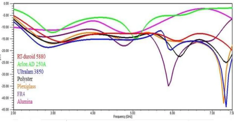
Figure 15 shows the parametric analysis with change in substrate permittivity on the proposed model. Except for Arlon and Alumina, the other materials based model is showing wide bandwidth. Ultralam 3850 (Liquid Crystal Polymer) substrate is showing superior performance over the other materials based antenna.
' 8 $
1 % % $
By considering different materials for the study on the proposed model, depending on the dielectric constant first we calculated the effective dielectric constant value and later calculated the width of the feed line and gap between ground planes to feed line [12] and placed in Table 1. Initially by taking centre frequency in the resonance band, we calculated wavelength (λc) corresponding to it. Later the overall dimensions of the antenna with change in substrate permittivity is calculated and tabulated in Table 2.
9 :2; :4; 1 %
(
! & ' * /
"97
'++- #7
'-<
!+'- 8 $ 8 . "&
h 1.56 1.6 1.56 1.56 1.5 1.6 1.2
ε
r 2.2 2.5 2.9 3.2 3.4 4.4 10.2εeff 1.6 1.75 1.95 2.1 2.2 2.7 5.6
W 4 3.675 3.35 3.025 2.7 2.375 2.05
9
! & ' * /
2 13.25 12.63 12.25 11.90 11.23 11 10.36
2 1,227 1.17 1.135 1.102 1.04 1 0.96
2! 5.401 5.148 4.994 4.851 4.576 4.5 4.224
2& 5.892 5.616 5.448 5.292 4.992 5 4.608
2 4.91 4.68 4.54 4.41 4.16 4 3.84
( 23.07 21.99 21.33 20.72 19.55 19 18.04
( 34.37 32.76 31.78 30.87 29.12 28 26.88
(! 15.71 14.97 14.52 14.11 13.31 13 12.28
(& 29.46 28.08 27.24 26.46 24.96 24 23.04
(' 57.44 54.75 53.11 51.59 48.67 47 44.98
(* 5.892 5.616 5.448 5.292 4.992 5 4.608
2 61.37 58.5 56.75 55.12 52 50 48
( 61.37 58.5 56.75 55.12 52 50 48
&
A novel broadband antenna is designed and its performance characteristics are demonstrated. The open slot can provide the perturbation into the wide slot antenna for circular polarization operation. In this model, with the use of wide tuning stub and slot on the ground plane the impedance and axial ratio bandwidths are improved. Three models are implemented and their parameters are discussed in detailed manner. The experimental results show that the antenna has excellent impedance bandwidth for the applications between 2)7 GHz. From the prototyped proposed model, an average gain of 3.2 dB and efficiency of more than 85% is attained in the desired band. Parametric analysis with change in substrate permittivity is also performed and the optimized dimensions for the studied materials are presented in this work.
=
1
"
1. Fu, S. (2009). Broadband circularly polarized slot antenna array fed by asymmetric CPW for L)band application. IEEE Antennas and Wireless Propag. Lett, 8, 1014)1016.
2. Wong, K. L. (2002). Compact and Broadband Microstrip Antennas. New York, John Wiley & Sons Inc.
3. Sze, J. Y. (2008). Axial)ratio bandwidth enhancement of asymmetric)CPW) fed circularly)polarized square slot antenna. Electron. Lett. 44(18), 1048) 1049.
4. Chang, T. N. (2009). Circular polarized antenna for 2.3)2.7 GHz Wi)MAX band. Microw. Opt. Technol. Lett. 51(12), 2921)2923.
5. Madhav, B. T. P. (2013). Substrate Permittivity Effects on the Performance of Slotted Aperture Stacked Patch Antenna. International Journal of Applied Engineering Research. 8(8), 909)916
6. Yeung, S. H. (2011). A Bandwidth improved circular polarized slot antenna using a slot composed of multiple circular sectors. IEEE Trans. Antennas Propag. 59(8), 3065)3070.
7. Sze, J. Y. (2003). Coplanar waveguide)fed square slot antenna for broadband circularly polarized radiation. IEEE Trans Antennas Propag. 51(8), 2141) 2144.
8. Sarat, K.; and Madhav, B. T. P. (2013). Coaxial Fed Rotated Stacked Patch Antenna. International Journal of Applied Engineering Research, 8(15), 1873)1879.
9. Sze, J. Y. (2008). Circularly polarized square slot antenna with a pair of inverted)L grounded strips. IEEE Antennas and Wireless Propag. Lett. 7, 149)151.
10. Chu, Q. X.; and Du, S. (2010). A CPW)fed broadband circularly polarized square slot antenna. Microw. Opt. Technol. Lett. 52(2). 409)412.
11. Chang, T. N. (2011). Wideband circularly polarized antenna using two linked annular slots. Electron. Lett. 47(13). 737)739.