A Review on UWB Microstrip Patched
Log-Periodic Antenna
Poonam Rajput
PG Scholar, Department of Electronics & Communication Oriental college of Engineering, Bhopal, Madhya Pradesh, India
Prateek Wankhade
Professor, Department of Electronics & Communication Oriental college of Engineering, Bhopal, Madhya Pradesh, India
Sumit Gupta
HOD, Department of Electronics & Communication Oriental college of Engineering, Bhopal, Madhya Pradesh, India
Abstract- Lately, ultra wideband (UWB) technology has appealed a lot awareness each within the industry and academia as a result of its low rate, advantage to manage excessive data price and fairly low vigor requirement. A UWB log-periodic antenna is the key add-ons for realizing the UWB systems. We observe, nevertheless, that designing a UWB log-periodic antenna to provide high efficiency is rather more difficult than it is when dealing with the conventional narrowband antennas. This paper focuses on the survey and analysis of planar printed UWB log-periodic antenna, and provides some representative performance outcome of previously designed UWB antennas to illustrate the advantages as well as drawbacks of those antennas. Existing state of progress of UWB log-periodic antennas is reviewed in the paper and a few future trends of UWB antenna designs are provided. Additionally, the topics of wideband enhancement techniques for UWB log-periodic antenna.
Keywords – : Log-Periodic Dipole Antenna (LPDA), Ultra Wide Band (UWB), Printed log-periodic dipole antenna (PLPDA), Power Spectral Density (PSD), Computer Simulation Technology (CST).
I.INTRODUCTION
The intensive development and vast utility of new generations of communique approaches have expanded the demand for company vast new antenna designs. Probably the most common requisites these methods pose on antennas are huge bandwidth, immoderate radiation readily, small measurement, and integration with developed-in circuits and MMICs. Considering the fact that these requisites, printed mm-wave antennas appear to be a suitable option of antenna technology for brand new wi-fi verbal exchange methods, as they preclude the want for cumbersome horn antennas and associated losses as a result of routing alerts off-chip to a transition from the active MMIC to the horn.
In telecommunication, the frequency spectrum is a uncommon commodity and each band is assigned for a exceptional software. A log-periodic antenna is a broadband, multi-detail, unidirectional, narrow-beam antenna that has impedance and radiation features that are most often repetitive as a logarithmic function of the excitation frequency.
miniaturized patch antenna for the extremely-wideband (UWB) offerings (3.1-10.6 GHz). A miniaturization aspect of 23% is finished with a usual and stable gain within the favored band. The radiation pattern is broadside, which finds suitable purposes within the UWB radars and scientific imaging. Furthermore, the time-discipline performance of the proposed antenna is investigated. A prototype mannequin of the proposed antenna is fabricated and measured as a proof of suggestion.
Fig.1Log-periodic patch antenna.
Fractal geometries are appropriate buildings for miniaturization and multi-banding of antennas. For this reason, a log-periodic formation of rectangular fractals is offered for broadside radiation in UWB offerings, where square slots are scale down within the square patches. The greater rectangular patches are equipped with square slots, but the smaller patches lack such slots, with a purpose to preserve the effectivity of radiation patterns at better frequencies. The geometry of log-periodic antenna is adjusted to accumulate 23% dimension reduction relative to the effortless rectangular patch array. The habits of the proposed log-periodic fractal configuration is further investigated in time-domain. A prototype model of the antenna is fabricated and measured which verifies its fascinating traits.
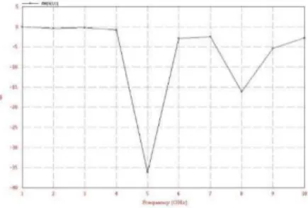
Fig.2 Return loss of proposed antenna.
Fig.3 Details of the design of the modified PLPDA on both sides of the substrate.
The antenna (see Fig.3) is printed on a NELTEC dielectric substrate (NX9300) with and a thickness equal to 0.8 mm. Consistent with, when scale and spacing factors are equal to 0.824 and 0.146, respectively, the expected acquire is 8 dBi, and the bandwidth is [2–4 GHz] with eight dipoles. In this case, the total top of the antenna is 98 mm, which exceeds our dimensional constraint. To shrink this size to 85 mm, the smallest and the longest dipoles are eliminated. This leads to the decreasing of the frequency bandwidth of the antenna. To be able to prolong the higher a part of the bandwidth, the lengths of the dipoles are adjusted. The size of the longest dipole is now 54 mm as an alternative of 63 mm earlier than modifications. Centered on the length of the longest dipole, the lengths of different dipoles are calculated.
Fig.4 Return losses of the proposed antenna versus, the distance between the antenna and the cable.
Noted that the antenna is also size-reduced—in fact, the height of the antenna proposed in this letter is 83.5 mm instead of 98 mm for an antenna designed using Carrel procedure. The antenna is fed by a coaxial cable, and the distance between this cable and the antenna has been optimized. An appropriate scale factor used for the width of dipoles has also been determined. As a result, the measured return loss is close to -20 dB between 2.2 and 3.9 GHz. The gain of this optimized antenna varies from 6 to 7 dBi. Theoretical results and measurements are satisfactory for all the significant parameters of the antenna. With the results described in this letter, we consider that this antenna should be a good candidate for high-power applications.
Fig. 6. Reflection coefficient of the designed LPDA antenna.
Prateek Wankhade et al[2013] A double-band attribute of multilayer aperture coupled microstrip log-periodic dipole antenna is discussed. Additional loading of patches is carried out and its effects are investigated. It is a probe
fed DQWHQQDIRULPSHGDQFHPDWFKLQJRIFRD[LDOFDEOH7KLVDQWHQQDZRUNVJRRGLQWKHIUHTXHQF\YDULHW\
GHz to 8.5 GHz. It is clearly a low price, mild weight, medium acquire antenna, which is used for wi-fi communique. The multilayer microstrip antenna constitution involves addition of a couple of layers one over the other. When a microstrip antenna is stacked with a superstrate dielectric layer, its properties like resonance frequency, attain and bandwidth are converted, which may impact the system efficiency.
Fig. 7. Return Loss
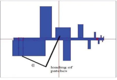
Fig. 8 Aperture Layer Structure
Alternatively on increasing the length of the loaded patch output all of the sudden deteriorates.
Multilayer aperture coupled antenna is offered. Probe feeding is used in this constitution as a feeding mechanism. Through using multilayer-stacked configuration, we are able to attain dimension discount and obtain just right performance at the tested frequency of 5 GHz. Through varying width of patch of the LPDA we are able to have higher return loss and for this reason bandwidth. It is also necessary in decreasing mutual inductance between the dipoles of the antenna, which reasons the reinforcement of the radiation by way of antenna.
In future this will also be proved as an excellent candidate of mutual inductance discount.
Fig. 9. LPDA structure
Ali Khaleghi et al [2011] A novel inspiration headquartered on time-reversal system is awarded to reap a non-dispersive log-periodic dipole array (LPDA) antenna concentrating on in an impulse radiating antenna (IRA). The idea is to use a passive interface circuit module at the feeding line of the antenna, which works because the time-reversal pre filtering. The proposed procedure results in a non-dispersive (high-fidelity) antenna via maintaining the identical LPDA structure that has the elements of the LPDA antenna in terms of radiation pattern, VSWR, achieve, and efficiency. The results show forty% growth in the constancy component of the antenna.
Fig. 10. (a) Top and (b) side view of the designed LPDA antenna.
A conventional time-reversal process wants the prolong traces and the lively obtain elements. A brand new simplified method is proposed with the aid of doing away with the energetic achieve elements. The antenna fidelity element is improved to 93%, and the radiated peak sign is expanded by using 31% in comparison with the height amplitude accomplished without TR procedure. The proposed system can be generalized to diminish the heart beat distortion of any directive UWB antenna.
The antenna elements are printed on a 3-layer substrate. The dielectric substrate is RT/Duroid-5880 with =2.2 the thickness of =0.787mm.The antenna elements are printed on a three-layer substrate. The dielectric substrate is RT/Duroid-5880 with and the thickness of mm.
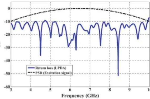
Fig. 11. Illustration of the antenna return loss and the PSD of the excitation.
The antenna is simulated by using the time- domain solver of CST-MWS. A modulated Gaussian pulse is applied to the antenna port [6]. The heartbeat has a wide bandwidth of 7 GHz for the power spectral density (PSD) of 10 dB. Fig.11 shows the PSD of the applied pulse.
Antenna parameter Miniaturized UWB Log-periodic Square Fractal Antenna. Low-Return-Loss Printed Log-Periodic Dipole Antenna A Printed LPDA Fed by a coplanar waveguide for Broadband application Multilayer Microstrip Log-Periodic dipole antenna for C and X band communication Impulse radiating Log-Periodic dipole array antenna using Time-Reversal Technique
Year 2015 2014 2013 2013 2011
III. CONCLUSION
The study motivation for this paper used to be miniaturization of Log-Periodic Microstrip Antenna utilizing quarter-wavelength transmission line. We selected this antenna when you consider that of its benefits in terms of low profile, cost, ease of fabrication, light weight and its advantage for conformal installations. A proximity coupling method used to be used to feed the radiating square patches. Two substrates with unique quarter-wavelength
et al. Chauloux et al. al. Wankhade et al. et al.
publication IEEE IEEE IEEE Elixir IEEE
dielectric Rogers RO4003 NX9300 ARLON AD450 FR4 RT/Duriod 5880
software - CST CST IE3D CST
Feeding
method -
Coaxial /differential
feeding Coaxial Feeding Aperture Couple feeding -
Return loss -45db -35 db -30 db -29.16 db -51db
Operating
frequency 2 – 11 GHz 1.5 – 4.5 GHz 3 - 6 GHz 1 – 10 GHz 3 – 10 GHz Usable
frequency 3.1 to 10.6 GHz 2 – 4 GHz 2.4 – 5.5 GHz 4.3-8.5 GHz 4.5 - 8.3 GHz
-Francesco Gaudiomonte, “A Printed LPDA Fed by a Coplanar Waveguide for Broadband Applications” IEEE Antennas And Wireless Propagation Letters, VOL. 12, 2013
[5] Ali Khaleghi, Member, IEEE, H. Sarbandi Farahani, Student Member, IEEE, and I. Balasingham, Senior Member, IEEE, “Impulse Radiating Log-Periodic Dipole Array Antenna Using Time-Reversal Technique”, IEEE Antennas And Wireless Propagation Letters, VOL. 10, 2011.
[6] Guohua Zhai, Yong Cheng, Qiuyan Yin, Shouzheng Zhu, and Jianjun Gao, “Gain Enhancement of Printed Log-Periodic Dipole Array Antenna Using Director Cell”,IEEE Transactions on Antennas And Propagation, VOL. 62, NO. 11, NOVEMBER 2014.
[7] Chao Yu, Student Member, IEEE, Wei Hong, Senior Member, IEEE, Leung Chiu, Member, IEEE, Guohua Zhai, Chen Yu, Wei Qin, and Zhenqi Kuai , “Ultrawideband Printed Log-Periodic Dipole Antenna With Multiple Notched Bands” IEEE Transactions on Antennas And Propagation, VOL. 59, NO. 3, MARCH 2014.
[8] Jia-Jun Liang, Jing-Song Hong, Member, IEEE,Jia-Bei Zhao,and Wei Wu, “Dual-Band Dual-Polarized Compact Log-periodic dipole Array
for MIMO WLAN Applications” IEEE Antennas and Wireless Propagation Letters 2014.
[9] Robert Lehmensiek and Dirk I. L. de Villiers, “Optimization of Log-Periodic Dipole Array Antennas for Wideband Omnidirectional
Radiation” IEEE Transactions on Antennas And Propagation, VOL. 63, NO. 8, AUGUST 2015.
[10] Benjamin S. Cook, Student Member, IEEE, and Atif Shamim, Member, “Inkjet Printing of Novel Wideband and High Gain Antennas on
Low-Cost Paper Substrate” IEEE Transactions on Antennas And Propagation, VOL.60, no.9, September 2012.
[11] Heng-Tung Hsu and Ting-Jui Huang, “A Koch-Shaped Log-Periodic Dipole Array Antenna for Universal Ultra-High-Frequency Radio Frequency Idenification Handheld Reader” IEEE Transactions on Antennas And Propagation, VOL. 61, no. 9, september 2013
[12] Robert Lehmensiek and Dirk I. L. de Villiers, “Constant Radiation Characteristic for Log-Perioidc dipole Array Antennas” IEEE Transactions on Antennas and Propagation, VOL. 62, no. 5, May 2014
[13] Guohua Zhai, Yong Cheng, Qiuyan Yin, Leung Chiu, Senior Member, IEEE, Shouzheng Zhu, Member, IEEE, and Jianjun Gao, Senior Member, IEEE, “Super High Gain Substrate Integrated Clamped-Mode Printed Log-Periodic Dipole Array Antenna”, IEEE Transactions on Antennas And Propagation, VOL. 61, NO. 6, JUNE 2013.