143 PACS number: 41.20.Jb
ELECTROMAGNETIC WAVE SCATTERING BY THE COATED IMPEDANCE CYLINDER
V.I. Vyunnik, A.A. Zvyagintsev Kharkov National University,
4, Svobody sq., 61077, Kharkov, Ukraine E-mail: [email protected]
In this work the boundary conditions for the impedance circular cylinder coated by a low contrast dielectric thin layer are derived. Expression for the reduced impedance of the cylinder is obtained. Conditions and applicability limits of the proposed approach are defined. Influence of the coating impedance on the reduced impedance of the cylinder is investigated.
Keywords: SCATTERING, DIELECTRIC LAYER, IMPEDANCE CYLINDER, BOUNDARY CONDITIONS, REDUCED IMPEDANCE.
(Received 04 May 2010, in final form 21 June 2010) 1. INTRODUCTION
Solution of the scattering problems for convex bodies coated by thin dielec-tric layer is of a great practical importance. While solving these problems, the approach emerged from [1] and studied in detail in [2] is usually used to obtain the boundary conditions. In the present work we apply the approach proposed in Ref. [3] and used by the author to derive the reduced boundary conditions for a plane unlimited perfectly conducting surface coated by thin dielectric layer. The feature of this approach is the fact that it allows to obtain the reduced impedance, i.e., the impedance of homogeneous cylinder without coating but with regard to its influence. In this work we show, that the given method without significant modifications can be used not only for plane but also for cylinder surfaces, including those with non-zero impedance coated by thin dielectric layer. The reduced boundary conditions for the impedance cylinder coated by a low contrast thin dielectric layer are derived and the applicability limits of such approach are defined.
2. OBTAINING OF THE REDUCED IMPEDANCE BOUNDARY CONDITIONS
To derive the reduced boundary conditions we consider the problem repre-sented in Fig. 1. Homogeneous cylinder of the radius 1 has the surface
im-pedance . Leontovich-Schukin imim-pedance boundary conditions hold on the cylinder surface 1
1 1
( ) z( )
E H , (1)
Fig. 1 – The problem geometry
Thin dielectric layer of the thickness with permittivity r and magnetic conductivity r is placed on the impedance cylinder surface 1. Under the
stipulation that k0 r r 1 (low contrast coating), where k0 is the wave
number, the dielectric field can be expanded in series of the layer thickness
1
( ) ( ) ( )
E E E . (2)
Here we are confined by two expansion terms that is completely acceptable for practical calculations.
From the Maxwell equations for complex amplitudes it is possible to find the ratio between the field components in the cylindrical coordinate system
1 1
r z
E E E i H , (3)
where is the circular frequency. Hence we write
( ) r z( ) ( ) ( )
E i H E E , (4)
where denotes the interior of the interface dielectric layer – vacuum. Substituting (4) into (2) we obtain (at 1)
1 1
1 1
( ) ( ) r z( ) ( )
E E i H E . (5)
In order to find the boundary conditions on the outer surface of the dielect-ric it is necessary to take into account that since in an ambient space r 1
=
1
( ) ( )
r
r
and taking into consideration the continuity of the field tangential compo-nents we obtain from (5)
1 1
1 1
( ) ( ) r z( ) ( )
r
E E i H E . (7)
Expression (7) connects the field on the outer boundary of impedance surface
1 + with the field on the outer boundary of dielectric field +. Since the
boundary conditions (1) hold on the impedance surface, substituting (7) into (1) we have
1 1
1 1
( ) ( ) ( ) ( )
z r z
r
H E i H E (8)
Equation (8) represents the equivalent boundary condition on the outer surface of the layer.
Let us to apply this condition back to the surface 1. For this purpose
we assume that now there is a vacuum between 1 and . We perform
the inverse expansion of the field into the Taylor series and express the field component on the interior of the interface vacuum-vacuum through the components on the outer boundary 1. Finally we obtain
1 1
( ) ( ) ( )
E E E (9)
Since for vacuum r 1, expression (3) can be written as
1 1
z
E E E i H , (10)
and, correspondingly,
1 1 1 1
( ) z( ) ( ) ( )
E i H E E . (11)
Substituting (11) into (9), we have (at 1)
1
1 1 1
1 1
( ) ( ) z( ) ( )
E E i H E . (12)
Taking into consideration the continuity of the tangential components on the interface vacuum-vacuum, we find from (12)
1
1 1 1
1 1
( ) ( ) z( ) ( )
E E i H E . (13)
1 1 1
1 1 1
( ) ( ) z( ) ( )
E E i H E . (14)
Comparing (13) and (14), we see that these expressions are equal if
1
1 1
1
1 1
1 1
1 1
( ) ( );
( ) ( );
.
z z
H H
E E (15)
We note, that the third equality in (15) will strictly hold only in the case when 0. However, it will be held approximately if << 1, that is the
applicability condition of the given approach to the cylinder structures. Substituting (15) into (8), we find the expression
1 1
1 1
1 1 1
( ) r z( ) ( )
r
E i H E . (16)
Substituting (16) into (13), we finally obtain the reduced boundary condi-tions on the surface 1
1
1 1
1 1
1 1
1 1 1
( )
1
( ) r ( ).
r z
r E
i i H E
(17)
It is important to emphasize that the boundary conditions (17) are assig-ned on the surface of homogeneous impedance cylinder without coating though they take into account its influence.
3. SOLUTION OF THE SCATTERING PROBLEM OF
ELECTRO-MAGNETIC WAVE ON A CYLINDER
Consider the irradiation of the cylinder of radius 1 by a plane Hz-polarized wave propagating in the XY-plane perpendicular to the cylinder axis. As it is known, the field components on the surface and outside the cylinder (at
1) are defined as
(1)
0 0
=0
( ) {n ( ) ( )} cos
z n n n n
n
H i J k R H k n , (18)
(1) 0
0 0
0 0
( )n { ( ) ( )} sin
n n n n
n Z
E i i n J k R H k n
(1)
0 0 0
0
( ) {n '( ) ' ( )} cos
n n n n
n
E iZ i J k R H k n . (20)
where 0 1, n 2, Jn,Jn',Hn(1),Hn(1)' are the Bessel and Hankel functions and their derivatives, respectively, and Z0 is the free space impedance.
Substituting expressions (18)-(20) into the boundary condition (17) on the cylinder surface (at 1), we obtain
(1) 1
0 0 1 0 1
1
(1)
1 1
0 1 0 1
1 1
2
(1) 0
0 1 0 1
1 0 1
( ) ( ) ( ) ( ) 1 ( ) ( ) . ' '
n n n
r n n n
r
n n n
r
iZ J k R H k
i i J k R H k
n iZ
J k R H k
k
(21)
Hence the factor Rn is equal to
3 ' 2 ' 2 2
0 1 0 1 0 1 0 0 1 0 0 1
2 3
2 2
1 0 0 1 0 1 0 1 0 1 0 1
3 3 2 2
0 1 0 1 0 1 0 1 0 1 0 1
2 2
0 0 1
( ) ( ) ( )
( ) ( ) ( )
( ) ( ) ( )
( )
n r n r n n
r n r n r n
r n r r n r r n
r n
R i k J k i k Z J k in Z J k
i n Z J k i k J k i k J k
k J k i k J k i k J k
i n Z J k in2 3 '(1)
1 0 0 1 0 1 0 1
'(1) (1) (1)
2 2 2 2
0 1 0 0 1 0 0 1 1 0 0 1
(1) (1) (1)
2 2 3 3
0 1 0 1 0 1 0 1 0 1 0 1
(1) 3
0 1 0 1 0
( ) ( )
( ) ( ) ( )
( ) ( ) ( )
( )
n r n
r n n r n
r n r n r n
r r n r r
Z J k i k H k
i k Z H k in Z H k i n Z H k
i k H k i k H k k H k
i k H k i k 2 2 (1) 2 2 (1)
1 0 1 0 0 1
(1) 2
1 0 0 1
( ) ( )
( ) .
n r n
n
H k i n Z H k
in Z H k
(22)
Hz-component of the field in far zone can be written as
(1)
0 0
=0
( ) {n ( ) ( )} cos
z n n n n
n
H i J k R H k r n , (23)
where r is the radius-vector to the point of observation.
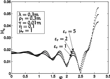
In Fig. 2 we present the directional patterns of the Hz-component of a complete field calculated using formula (23). Obtained results at the rela-tively small coating thickness ( 0,04 1) with a graphical accuracy coincide
with the results calculated by the formula in [4].
Expression (22) is obtained from the boundary conditions (17) applied to homogeneous impedance uncoated cylinder but with the modified impedance considering the influence of dielectric layer. On the other hand, it is known that for the plane Hz-polarized wave incident on the impedance uncoated cylinder of the radius 1, Rn can be written as
0 1 0 1
(1) (1)
0 1 0 1
( ) ( )
( ) ( )
'
n p n
n '
n p n
J k i J k
R
H k i H k (24)
Equating expressions (24) and (22) for the reduced impedance we get
3 2 2 3
1 0 1 0 1 0
2 2
1 0 1 0
2 3
2 2 2 2 2 2 2
1 0 1 0 1 0 1 0 0 0
1
(
( )
).
p r r r r r
r
r r r r
i k i k i k
k Z
i n Z i n Z i k k i n Z i n Z
(25)
Fig. 2 – Hz-component of a complete field in far zone at the incidence of Hz-polarized plane wave on the impedance cylinder
In Fig. 3 we show the dependence of the reduced impedance of the cylinder on the coating impedance. An important fact is the following: though both the impedance of the cylinder and the coating impedance have real values, the reduced impedance represents purely imaginary quantity.
Fig. 3 – Dependence of the reduced impedance of the cylinder on the impedance of dielectric coating at different coating thickness
4. CONCLUSIONS
The reduced boundary conditions for the impedance cylinder coated by a low contrast thin dielectric layer are obtained. The condition, under which the mentioned approach can be applied to cylindrical structures, is defined. The expression for the calculation of the directional pattern of a complete field for homogeneous impedance cylinder with the reduced impedance is derived. Shown, that the given solution completely corresponds to the solution for the corresponding coated impedance cylinder. This approach can be easily applied to circular impedance cylindrical structures coated by some low contrast dielectric layers.
REFERENCES
1. S.M. Rytov, ZhETF10, 180 (1940).
2. T.B.A. Senior, V.J. Volakis, Approximate Boundary Conditions in Electromagnetics
(London: Institution of Engineering and Technology: 1995).
3. L.A. Vainstain, Teoriya difraktsii i metod faktorizatsii (M.: Sovetskoe radio: 1966). 4. T.B.A. Senior, Approximate boundary conditions, part 2: Tech. Rep. RL-862
(Uni-versity of Michigan, Radiation Laboratory: 1990).
5. V.I. Vyunnik, A.A. Zvyagintsev, Radiotekhnika: Vseukr. mezhved. nauch.-tekhn. sb.