*e-mail: [email protected]
1. Introduction
Galvanized steel is one of the most commonly used metallic materials for industrial applications against corrosion. This anticorrosion protection can be enhanced from the use of coatings. Recently developed coatings include hybrid organic-inorganic layers obtained by sol-gel deposition on the heterogeneously rough surface of the substrate. The present study is pertinent for the future industrialization of the sol-gel process, working on substrates for industrial applications1.
Organic–inorganic hybrid materials have been of great scientiic and technological interest in the last few decades due to the novel and improved properties of these materials2,3. Hybridization is not only a creative alternative to the design of new materials but also offers unique opportunities to develop innovative industrial applications4. These materials combine the hardness, wear resistance and thermal stability of the ceramic component with the flexibility, transparency and tunable adhesion of the organic materials5-11. The sol-gel method allows to control the synthesis of multifunctional hybrid materials, where the organic, inorganic and, in some cases, biological constituents are mixed at a nanometer scale12–16.
Additionally, the sol-gel process is an innovative technology due to its properties of surface protection together with the simplicity of the process and the economic viability. The process has the following advantages: (I) The stoichiometry is easy to control and adjust4, (II) it allows to fabricate
high‑purity ilms with evenly distributed components17, and
(III) the ilm can be processed under normal pressures and low temperature. In the last few decades, a large number of hybrid materials produced through the sol–gel process have been prepared using various inorganic precursors and polymers18,19. The main steps are the hydrolysis and condensation of metal alkoxides to obtain metaloxane chains. These chains generate sols that can be used to coat numerous metallic and alloy substrates to protecting them against corrosion20–26.
The hybrid ilms with thick layers are recommended to promote an eficient barrier effect between the substrate and the environment. However, there are limitations for the increased thick layers, aiming to avoid delamination problems27. Secondly, the sol viscosity can be increased via
temperature modiication prior to coating, but in this case, the kinetics of the hydrolysis and condensation reactions change and may modify the mechanical and physical properties of
New Sol-gel Formulations to Increase the Barrier Effect of a Protective Coating
Against the Corrosion and Wear of Galvanized Steel
Sandra Raquel Kunsta,b, Henrique Ribeiro Piaggio Cardosoa, Lilian Vanessa Rossa Beltramia*,
Claúdia Trindade Oliveirac, Tiago Lemes Menezesd, Jane Zoppas Ferreirac, Célia de Fraga Malfattia
aLaboratório de Pesquisa em Corrosão – LAPEC, Universidade Federal do Rio Grande do Sul
– UFRGS, Avenida Bento Gonçalves, 9500, Porto Alegre, RS, Brazil
bPrograma de Pós-graduação em Engenharia de Processos e Tecnologia (PGEPROTEC) da
Universidade de Caxias do Sul (UCS), Caxias do Sul, RS, Brazil
cInstituto de Ciências Exatas e Tecnológicas – ICET, Universidade Feevale,
RS-239, 2755, Novo Hamburgo, RS, Brazil
dLaboratório de Corrosão, Proteção e Reciclagem de Materiais – LACOR, Universidade Federal
do Rio Grande do Sul – UFRGS, Avenida Bento Gonçalves, 9500, Porto Alegre, RS, Brazil
Received: April 8, 2014; Revised: February 4, 2015
This study proposes a new pretreatment method that uses alkoxide precursors with a plasticizing agent; the purpose of this study is to improve the electrochemical and mechanical properties of a galvanized steel surface. Galvanized steel was covered with a hybrid ilm obtained from a sol that consisted of two alkoxide precursors, 3 - (trimethoxysilylpropyl) methacrylate (TMSM) and tetraethoxysilane (TEOS), with nitrate cerium in a concentration of 0.01 M and a polyethylene glycol (PEG) plasticizer. The hybrid coatings were obtained by dip-coating method with various concentrations of plasticizer (0, 20, 40 and 60 g.L-1). The hybrid ilms were analyzed by scanning electron microscopy (SEM), proilometry, contact angle measurements, a tribometer with the type-setting ball on the plate and electrochemical tests. The addition of the plasticizer into the hybrid ilms improves the corrosion resistance behavior compared to the sample without the plasticizer. The addition of 20 g.L-1 of plasticizer showed the best performance in the electrochemical tests. The mechanical behavior results indicated that higher PEG concentrations resulted in ilms with enhanced durability.
the gel. Finally, a plasticizing agent can be introduced28. This last route was chosen in this study as it can be easily adjusted and performed29.
The aim of this work is to coat galvanized steel with a hybrid ilm obtained by a dip‑coating process from a sol consisting of alkoxide precursors, 3 - (trimethoxysilylpropyl) methacrylate (TMSM) and tetraethoxysilane (TEOS), with nitrate cerium in a concentration of 0.01 M20. The influence of the concentrations (0, 20, 40 and 60 g.L-1) of polyethylene glycol (PEG 1500) plasticizer added in the sol formulation was evaluated.
2. Experimental
2.1. Surface preparation
The galvanized steel substrates (2 cm × 4 cm) were degreased with a neutral detergent at 70 ºC by immersion for 10 minutes. The samples were after rinsed with deionized water and dried, then rinsed with ethanol and dried. The chemical composition (%wtmáx) of the galvanized steel substrates is 0.15C, 0.6Mn, 0.04S, 0.04P and Zn.
2.2. Elaboration of hybrid ilms
The hydrolysis reactions were conducted by alkoxide precursors (TMSPMA) 3 - (trimethoxysilylpropyl) methacrylate (C10H20SiO5) and (TEOS) tetraethoxysilane (C8H20SiO4) with the addition of cerium nitrate in a concentration of 0.01 M. Ethanol and water were used as solvents. PEG 1500 was added to the sol formulation in different concentrations (0, 20, 40 and 60 g.L-1). The hydrolysis time was 24 hours.
The coated samples were prepared by using a dip coater (brand Marconi - model MA765). The samples were dipped in sol at a withdrawal speed of 100 mm min-1 with a residence time of 5 minutes23.
The hybrid ilms were then thermally cured at 90 ºC ± 2 for 20 minutes in a furnace (brand De Leo - model TLK48). The process flow diagram is shown in Figure 1 and the Table 1 presents the description of the samples studied.
2.3. Experimental techniques
The morphological characterization was performed by scanning electron microscopy (SEM) with a JEOL 6060 with an acceleration voltage of 20 kV. The samples were observed from the top view and in a cross-sectional view to determine the layer thickness. The surface micro-roughness was evaluated in a contact proilometer (PRO500 3D).
The wettability of the hybrid ilms was evaluated by contact angle measurements with the sessile drop method in equipment developed by the Laboratory of Corrosion Research (LAPEC) at UFRGS. The contact angle was determined by using image analyses software.
The corrosion performance of the coatings was evaluated by open circuit potential (Ecorr) monitoring, polarization curves and electrochemical impedance spectroscopy (EIS) measurements in a 0.05 M NaCl solution. Kozhukharov et al. 30 also used
0.05 M NaCl to ensure a suficiently low concentration to
Figure 1. Schematic illustration of the steps of the dip-coating technique.
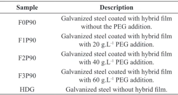
Table 1. Description of the samples.
Sample Description
F0P90 Galvanized steel coated with hybrid ilm without the PEG addition. F1P90 Galvanized steel coated with hybrid ilm
with 20 g.L-1 PEG addition.
F2P90 Galvanized steel coated with hybrid ilm with 40 g.L-1 PEG addition.
F3P90 Galvanized steel coated with hybrid ilm with 60 g.L-1 PEG addition.
allow for the observation of corrosion inhibitor effects. A three-electrode cell was used to perform the analyses, with a platinum wire as a counter-electrode and a saturated calomel electrode (SCE) as the reference electrode. The area of the working electrode was 0.626 cm². The polarization curves were collected at a scan rate of 1 mV s-1 in a potential interval between 200 mV (below OCP – open circuit potential) and 400 mV (above OCP). The data obtained from the potentiostatic polarization measurements were treated with the NOVA® software to obtain the corrosion rate (i
corr), the corrosion potential (Ecorr) and the polarization resistance (Rp).
For the EIS measurements, the systems were previously monitored for 96 hours. The amplitude of the EIS perturbation signal was a sinusoidal 10 mV (rms signal), and the frequency range studied was from 100 kHz to 10 mHz using a NOVA® frequency response analyzer and a AUTOLAB PGSTAT 30 potentiostat. The results for the systems were itted using electrical equivalent circuits (EEC) with the NOVA® program. The consistency of the experimental data
was veriied with the Kramers‑Kronig transform (KKT), and the data that did not match were removed.
Wear assays were performed with a computationally controlled CETR UMT (Universal Micro Tribometer) tribometer with the type-setting ball on the plate (Figure 2). The wear test was conducted with reciprocal linear movement by a sphere of alumina with a 7.75 mm diameter. A constant force of 1.5 N, a frequency of 2 Hz and a track length of 2 mm were used as the wear assays parameters.
3. Results and Discussion
3.1. Morphological characterization
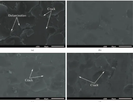
Figure 3 shows the SEM micrographs for the hybrid ilms studied before the electrochemical tests. The presence of cracks on the hybrid ilms F0P90 (Figure 3a), F2P90 (Figure 3c) and F3P90 (Figure 3d) can be observed; for the last ilm, this phenomenon is more pronounced. The fact that the sample F0P90 (Figure 3a) had more cracks and delamination on the ilm can be associated with the absence of the plasticizer agent, resulting in a brittle and porous structure that is characteristic of a ceramic material31.
Furthermore, the presence of cracks on the hybrid ilms was also observed with higher PEG concentrations of 40 and 60 g.L-1, which correspond, respectively, to the F2P90 and F3P90 systems. It seems that the addition of the plasticizer agent in excess interferes with the hydrolysis of the alkoxide precursors, forming only dense interlaced networks of PEG and Figure 2. Schematic representation of the tribological test system.
causing cracks on the ilms32. The system F1P90 (Figure 3b), which presents the lowest PEG concentration (20 g.L-1), apparently has enough of the plasticizer incorporated in the hybrid ilm to promote the elaboration of a regular and uncracked ilm. As Certhoux et al.22 observed, during the process of curing, the unpolymerized organic components can volatilize and create tensioned regions and defective areas, leaving the ilm more susceptible to corrosion in those regions.
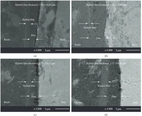
The layer thickness of the ilms was determined by cross-section analysis from images obtained by SEM (Figure 4). Figure 5 shows images obtained by elemental distribution using EDS for cross sections of the hybrid ilms, which shows the hybrid ilm layer by mapping the element silicon as well as the substrate by mapping the elements zinc and iron.
All ilms with added PEG (F1P90, F2P90 and F3P90) demonstrated an increase in thickness compared to the ilm without PEG (F0P90). It seems that the addition of the flexibilizing agent in excess interferes with the hydrolysis of the alkoxide precursors, forming only dense interlaced networks of PEG and causing an increase in the thickness of the layer33. This increase in the layer thickness was
achieved with the addition of flexibilizing PEG in the hybrid ilms. However, only the system with the lowest monomer concentration (20 g.L-1) did not interfere with the reactions of hydrolysis and condensation and showed an uncracked ilm. For the other systems, the higher concentrations of PEG (F2P90 and F3P90) resulted in the formation of a ilm with cracks due to the cross-linked PEG chains31.
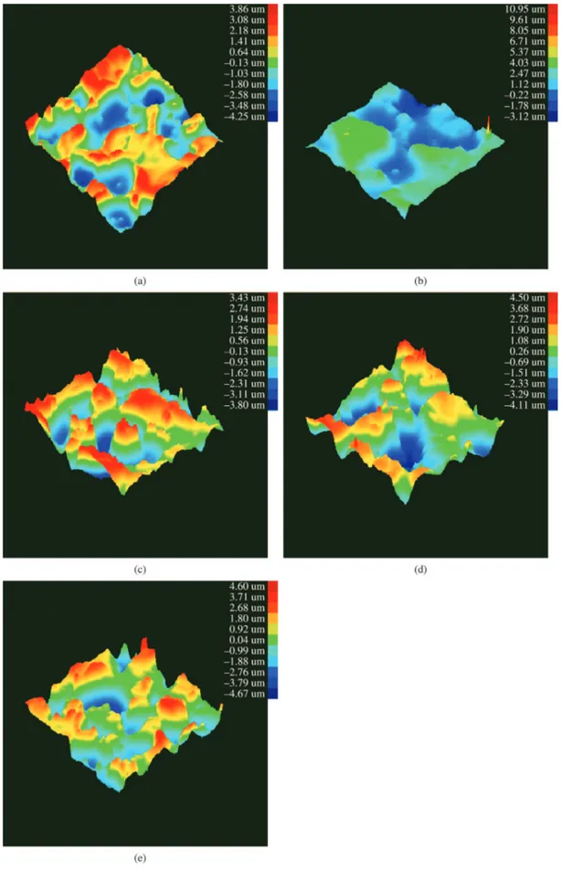
Figure 6 shows tridimensional images obtained by proilometry for uncoated galvanized steel and for all hybrid ilms studied. The roughness values are summarized in Table 2, where Ra is the arithmetic average, Rms is the average square roughness and Ry is the maximum or peak-to-peak roughness. Sample F1P90 presented the lowest value of roughness (Figure 4 and Table 3) compared to all the studied samples, which means that in this system, a regular structure
was formed in the ilm. In other words, organic monomers formed a crystal structure with the silicon atoms. This structure is regular, homogenous and compact34. Moreover,
the temperature of 90 ºC seems to have been suficient to cross‑link this ilm without the presence of cracks.
All the samples with the addition of the PEG plasticizer presented smaller roughness values than the uncoated galvanized steel and the sample without the plasticizer. Additionally, the presence of the plasticizer in the coating on rough and heterogeneous galvanized steel surfaces increases the layer thickness in a uniform and homogeneous way. However, higher plasticizer concentrations (40 and 60 g.L-1) produced higher roughness values compared to the F1P90 sample (20 g.L-1), which can be associated with the phenomenon observed by Certhoux et al.22 due to the volatilization of unpolymerized organic components during the curing process, contributing to the increased ilm roughness.
Table 2 is a summary of the contact angle values for the different systems studied. These results show that the hybrid ilms F1P90 and F2P90 presented highest contact angles and consequently the smallest surface wettabilities. These systems are associated with the lowest concentrations of PEG (20 and 40 g.L-1). Low concentration of PEG did not interfere with the reactions of hydrolysis and condensation of the silane precursors TEOS and TMSM and therefore provided the most compact three-dimensional grid formations, which blocked the absorption of water. Therefore, the ilms F1P90 and F2P90 are more hydrophobic than the sample without PEG (F0P90).
3.2. Electrochemical characterization
Open circuit potential (OCP) monitoring was conducted in a NaCl 0.05 M solution to verify the potential variation with time. The results are shown in Figure 7a. The hybrid ilms F1P90 and F3P90 demonstrated potential shifts in the positive direction compared to the uncoated galvanized steel; i.e., these samples showed a gentler corrosion potential value than the substrate, indicating an improvement in corrosion resistance32.
This behavior is associated with the barrier layer between the substrate and the electrolyte provided by the hybrid ilms. This behavior is reinforced by the more regular surface obtained for these F1P90 samples, as seen in the SEM images of Figure 3, the surface roughness measurements (Table 2 and Figure 6) and the high layer thickness values found for the F3P90 sample (Figure 4).
However, for samples with higher concentrations of the plasticizer polyethylene glycol, i.e., samples F0P90 and F2P90, the potential remained near that for the uncoated galvanized steel. This result shows the fragility of these coatings that allow permeation of the electrolyte through the ilm. Although the formulation of system F2P90 with the addition of plasticizer has promoted an increase in the layer thickness (Figure 4) compared to the system without PEG (F0P90), this system formed a weak and porous structure due to the formation of intertwined and dense PEG by weak bonds (hydrogen bonds), causing cracks and peeling of the ilms formed and contributing to poor performance in corrosion resistance.
In Figure 7b, potentiodynamic polarization curves for the studied samples are shown. Table 3 shows the correspondent Table 2. Comparative table of roughness among the studied systems
by Proilometer and Layer thickness of the hybrid ilms.
Samples Roughness Contact
angle Ra (µm) Rms (µm) Ry (µm)
F0P90 1.40 ± 0.18 1.62 ± 0.23 8.10 ± 0.71 71° ± 3.2 F1P90 1.20 ± 0.17 1.34 ± 0.24 7.83 ± 0.80 80° ± 4.2 F2P90 1.28 ± 0.19 1.52 ± 0.19 7.23 ± 0.83 80° ± 2.9 F3P90 1.31 ± 0.22 1.58 ± 0.16 8.61 ± 0.88 73° ± 1.5 HDG 1.34 ± 0.15 1.60 ± 0.21 9.27 ± 0.83 66° ± 0.5
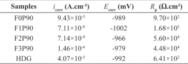
Table 3. Obtained data from Tafel extrapolation. Samples icorr (A.cm
-²) E
corr (mV) Rp (Ω.cm²)
F0P90 9.43×10⁻⁵ -989 9.70×10²
F1P90 7.11×10⁻⁸ -1002 1.68×10⁵
F2P90 7.14×10⁻⁸ -966 5.60×10⁴
F3P90 1.46×10⁻⁶ -979 4.48×10⁴
Figure 4. Cross section micrographs obtained by SEM analysis for the hybrid ilms: (a) F0P90, (b) F1P90, (c) F2P90 and (d) F3P90.
corrosion potential (Ecorr) values as well as the corrosion current density (Icorr) and the polarization resistance (Rp) determined from Tafel slopes extrapolation.
The results (Figure 6b) showed that all the hybrid ilms studied promoted an increase in polarization resistance (Rp) and a decrease in corrosion current density (icorr) values related to galvanized steel, demonstrating the protective behavior of these ilms. For the polarization curves (Figure 7b), at potentials of approximately -1.05 to -1.23 V vs SCE, the cathodic reaction of the hybrid ilms decreases signiicantly compared to that of uncoated galvanized steel because the cerium nitrate inhibitor action in the hybrid ilm acts cathodically, whereas the anodic reaction is not inhibited by a high potential. This result can be associated with two factors: a lower diffusion of O2 or a decrease of the cathodic area.
Moreover, the ilm F3P90 showed the best performance among the hybrid ilms studied, which indicates that although the concentration of 60 g.L-1 of polyethylene
glycol is insuficient to prevent the tensions caused by the silane precursors (TEOS and TMSM) during hydrolysis and condensation, the addition of a plasticizer signiicantly increased the hybrid ilm thickness and signiicantly reduced cracks compared to the sample without PEG (F0P90).
However, note that the F0P90 showed the worst performance among the hybrid ilms studied, which is related to the fact that during the curing process, hydrophobic siloxane bonds are formed in the ilm network, which hinder water penetration35. However, neither the precursor hydrolysis nor cross-linking (polycondensation) during curing is complete. Thus, non-hydrolyzed ester and hydrophilic OH groups are present in the ilms’ structures. These latter groups, ester and OH, favor water uptake, whereas the former group, siloxane, can be hydrolyzed when the ilms are exposed to the electrolyte, further increasing the number of hydrophilic OH groups in the ilm structure. This result is in agreement with the contact angle analysis (Table 2).
Although the hybrid ilm F0P90 presents only covalent bonds with organic and inorganic precursors6,36, the formulation of F0P90 promoted a complete porous ceramic structure, which is brittle in the ilm after TEOS and TMSM hydrolysis and cross-linking and provides poor corrosion protection, as seen in SEM images of Figure 3.
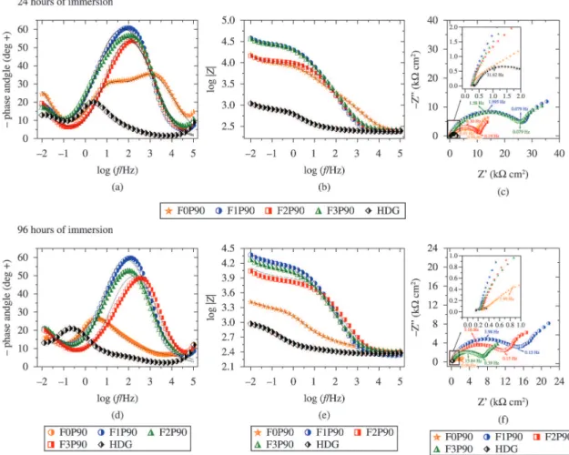
Figure 8 shows the Nyquist and Bode diagrams obtained by electrochemical impedance spectroscopy for galvanized steel that is both uncoated and coated with the studied ilms F0P90, F1P90, F2P90 and F3P90, performed after 24 and 96 hours in a solution of 0.05 M NaCl. The quality of these its can be veriied by the continuous lines in the Bode diagrams (Figures 8a, 8b, 8d and 8e).
From the Nyquist diagrams (Figures 8c and 8f), it is possible to observe that although the curves are similar in shape, they differ in order of magnitude. Therefore, the same fundamental phenomena could have occurred in all these coatings but over a different effective area in each case36.
The diameter of the arc can be regarded as the sample’s polarization resistance (Rp)36. The specimen coated with the lowest PEG concentration shows the largest semicircle, indicating that this specimen has a better anticorrosive performance in comparison with the other hybrid ilms studied. The resistance attained by this sample (F1P90) was 23 times greater after 24 hours of immersion in 0.05 M NaCl and more than 55 times greater after 96 hours compared to that of the uncoated galvanized steel, demonstrating the protective action of this hybrid ilm. The performance of the sample F1P90 is associated with the fact that the small increase in the branching of the ethylene oxide (20 g.L-1) radical was
suficient to decrease the rate of the triorganosilane groups’ condensation reaction. The condensation of the tetrafunctional alkoxides was also retarded in the presence of this monomer (PEG) due to the increased steric hindrance in the transition state; therefore, a more flexible ilm was obtained with better adhesion to the substrate and hence an improvement in the anticorrosive properties of this coating37. The system resistance is 7 times higher than that of the sample without PEG (F0P90) after 96 hours of assay.
a weak and porous structure resulted due to the formation of intertwined and dense PEG chains formed only by weak bonds (hydrogen bonds), causing cracks in the ilms, contributing to the poor performance of these samples in corrosion resistance and consequently not resisting. Long periods of immersion.
This result reveals the fragility of these coatings, allowing the permeation of the electrolyte through the ilm. The plasticizer addition promoted the formation a weak and porous structure despite has promoted an increase of the layer thickness (Figure 4). This behaviour might be explained by the formation of interlaced and dense PEG chains formed only by weak bonds (hydrogen bonds), causing cracks in the ilms.
The Bode diagrams (Figures 8a, 8b, 8d and 8e) observed after 24 hours of immersion for the systems F1P90, F2P90 and F3P90 showed higher phase angles and impedance modulus values that remained high after up to 96 hours of immersion when compared to system F0P90 and uncoated galvanized steel. This good electrochemical performance is associated with the addition of PEG at concentrations of 20, 40 and 60 g.L-1 in these ilms, which improves the hydrolysis and condensation37, increases the thickness of the layer (Figure 4) and enhances the barrier effect against corrosion.
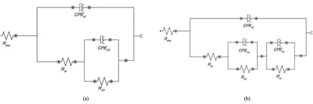
The EIS was used in the present work to characterize the corrosion behavior of the developed coatings. A more detailed interpretation of the EIS measurements was performed by itting the experimental plots using equivalent electrical circuits models, which were proposed to simulate the electrochemical behavior of the coatings studied (Figure 9). These models were based on the combination of resistances, capacitances and other elements that should have a physical meaning, most likely related to the electrochemical response of the system. Table 4 presents the electrical parameter values obtained by itting the equivalent electrical circuit from the experimental EIS data, which were obtained for the hybrid ilms F0P90, F1P90, F2P90 and F3P90 for 96 h of immersion in a 0.05 M NaCl solution (the error % associated with each parameter value is given in parenthesis.). It was not possible to it impedance curves for the irst hour of immersion for hybrid ilm samples due to their instability in this solution. These instabilities in the irst few hours of the EIS experiments can be correlated with the modiication of the EOC observed during the initial immersion period38. These results are
in Tables 4 shows that the errors involved in the itting procedure were less than 10% in some cases and less than 5% in most cases.
In several circuits, the capacitance was substituted by a CPE to take into account the non-ideality of the systems. In these circuits (Figure 9a), Relec represents the electrolyte resistance, and RSil and CPESil represent, respectively, the resistance and a constant phase element associated with the hybrid ilm barrier resistance. In the same circuit, ROx and
CPEOx represent the resistance and a constant phase element indicating an acceleration of the interfacial process associated with the zinc oxide on the substrate surface.
The same equivalent circuit model (Figure 9a) was proposed for the electrochemical behavior simulation of samples F1P90, F2P90 and F3P90 at all immersion times studied (24, 48, 72 and 96 hours). These samples showed two time constants: one time constant at a high frequency range, which was associated with the barrier resistance of the hybrid ilm, and the other constant representing medium to low frequency range elements, which were attributed to
the presence of an oxide on the metal/coating interface. This behavior was observed by other authors40,41.
However, for the sample F0P90, another equivalent circuit model (Figure 9b) was proposed, where Rcp and
CPEcp were added and represent, the corrosion process developed under the hybrid ilms. This model conirms the poorer electrochemical behavior of these systems.
For the uncoated galvanized steel (Table 4), two time constants were observed over the entire immersion time (1, 24, 48, 72 and 96 h). The phenomenon at low frequencies may be related to the diffusion limitations caused by the high reaction rate. The response of the charge transfer becomes shifted to lower frequencies as the active area expands, increasing the capacitance. Meanwhile, another process with a very low resistance appears at the medium frequency, which may result from the cathodic reaction or from the precipitation of zinc hydroxide as shown below42.
Zn2+ + 2OH− → Zn(OH) 2
Table 4. Electrical elements itted values for the samples studied up to 96 h of immersion in a 0.05 M NaCl solution.
Sample Time (hours)
RS
(Ω.cm2)
RSil
(kΩ.cm2)
CPESil-Q
(µF.cm2) CPESil-n
ROx (kΩ.cm2)
CPEOx-Q
(µF.cm2) CPEOx-n
Rdf (kΩ.cm2)
CPEdf-Q
(µF.cm2) CPEdf-n
F0P90
24 h 217 (1.8) 1.61 (6.6) 5.60 (4.8) 0.65 (3.1) 9.78 (5.8) 15.70 (6.2) 0.67 (4.3) 35.04 (5.6) 1.17 (7.2) 0.84 (8.3) 48 h 204 (2.0) 1.22 (2.0) 10.7 (5.4) 0.70 (3.3) 6.93 (7.8) 17.7 (6.6) 0.70 (4.9) 35.04 (10.3) 1.40 (9.0) 0.72 (9.7) 96 h 189 (1.6) 1.11 (8.7) 77.9 (3.6) 0.40 (7.6) 2.19 (9.8) 36.8 (4.5) 0.79 (4.2) 7.50 (1.4) 3.36 (7.1) 0.73 (9.1)
F1P90
24 h 221 (1.4) 23.5 (7.8) 4.48 (3.3) 0.78 (2.3) 74.0 (5.6) 309 (3.8) 0.66 (1.4) 48 h 214 (1.4) 17.8 (9.0) 4.57 (3.0) 0.79 (2.3) 59.8 (5.0) 410 (4.2) 0.62 (1.5) 96 h 207 (1.6) 12.7 (4.9) 4.75 (2.0) 0.79 (9.4) 47.1 (5.4) 329 (5.2) 0.59 (1.9)
F2P90
24 h 227 (1.2) 9.82 (5.4) 4.81 (3.5) 0.76 (2.6) 25.0 (3.2) 936 (4.4) 0.6 (1.0) 48 h 220 (1.8) 7.40 (4.9) 5.16 (9.7) 0.73 (3.9) 22.3 (5.1) 683 (6.6) 0.51 (1.9) 96 h 217 (1.9) 5.89 (5.7) 4.92 (6.6) 0.72 (2.2) 18.0 (5.1) 686 (7.2) 0.49 (1.9)
F3P90
24 h 231 (1.5) 23.8 (6.9) 5.69 (3.7) 0.72 (1.5) 80.3 (3.1) 362 (4.9) 0.64 (3.2) 48 h 236 (1.6) 14.6 (7.3) 6.37 (2.6) 0.73 (2.1) 52.6 (7.3) 306 (4.8) 0.58 (2.1) 96 h 238 (1.5) 10.3 (2.0) 7.62 (9.2) 0.73 (7.9) 48.6 (5.4) 385 (4.6) 0.56 (1.8)
HDG
24 h 150 (1.4) 468 (3.1) 108 (3.2) 0.74 (8.1) 468 (3.1) 6.5×10⁻³ (2.7) 1155 (0.9)
48 h 148 (1.1) 252 (7.3) 280 (9.8) 0.66 (8.1) 252 (7.3) 14.6×10⁻³ (6.8)
In this case, note that the HDG showed lower impedance moduli and phase angles (Figures 8a and 8d) relative to the hybrid ilms studied (F0P90, F1P90, F2P90 and F3P90) after 96 hours of immersion.
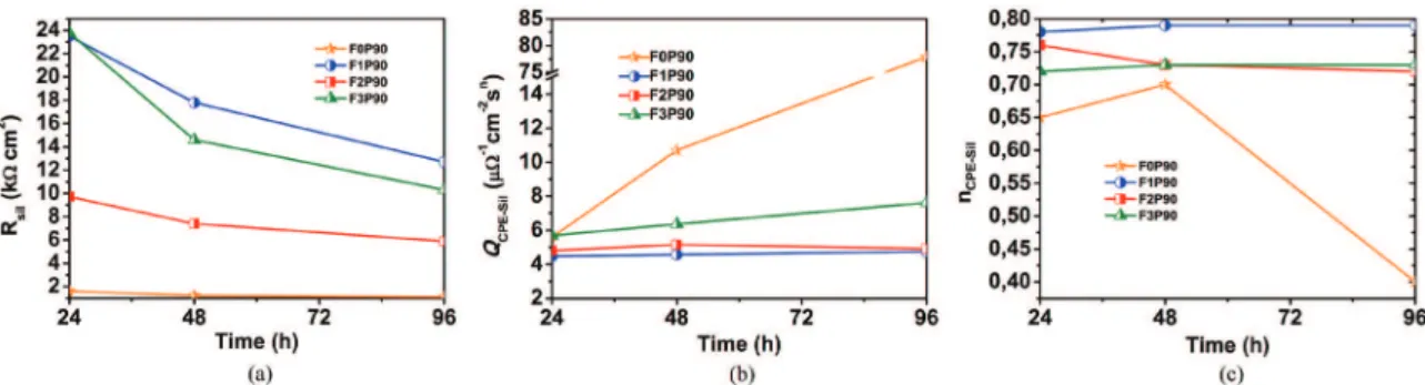
Figure 10 shows the evolution of the coating properties (i.e., the resistance and capacitance, respectively) as a function of the immersion time. Generally, the high frequency resistance values (Figures 9a) decreased during the irst hours of immersion due to the development of conductive pathways inside the ilm43.
The samples F1P90 and F3P90 exhibited the highest resistance at all times (Figure 10a); for the sample F1P90, this result is due to fact that the amount of ethylene oxide (20 g.L-1) was enough to increase steric hindrance in
the transition state; as a result, a more flexible ilm was obtained with better adhesion to the substrate and hence an improvement in the anticorrosive properties of this coating. For the sample F3P90, this higher resistance is associated with the high layer thicknesses obtained for this system (Figure 4) compared the other samples F0P90 and F2P90.
The evolution of a coating resistance is a major characteristic of the barrier properties of a protective layer44. The system that showed a better performance, i.e., good barrier properties, was sample F1P90. However, the F3P90 sample showed a sharp reduction of its resistance values from 24 hours to 48 hours of immersion, indicating that this coating. Loses its barrier properties after 48 hours of immersion. Such a rapid decrease is related to the formation of new defects and pores in the coatings. Conversely, the resistance of the F2P90 coating decreases slowly over an immersion time of 96 hours, which reflects the stability of the coating.
In Figure 10, the samples F1P90 and F3P90 had capacitance values two times smaller than the samples F0P90 and F2P90, highlighting the performance properties of the barriers of these hybrid ilm. Furthermore, there is an increase in the capacitance of the F0P90 coating after 48 hours of immersion, which can be explained by a reduction in the coating thickness and/or conductivity and therefore an increase in the porosity. Moreover, a slight increase in the capacitance is observed in the F1P90 sample (Figure 10b) after the 48 hours immersion, which is associated with the absorption of electrolytes.
A value of n=1 corresponds to a smooth surface, and therefore CPE should be substituted by an ideal capacitor C. n=0.5 suggests a diffusion response or a porous material, and 0.5<n<1 is associated with heterogeneous, rough or non-homogeneous current distribution, as can be observed in the sample F0P9045,46. The evolution of the middle frequency time constant (Figure 8) would then be related to a change of the composition and to a reinforcement of the native zinc oxide layer by the cerium oxides. This hypothesis seems to be consistent with the evolution of the values of the n values (from 0.4 to 0.7) highly suggests an evolution of the system from a diffusion limited process to a charger transfer limited process as the oxide layer is reforced14.
Figure 11 shows images for all studied hybrid ilms obtained at the end of EIS assays after 96 hours of immersion in NaCl 0.05 M. In this Figure 11, the sample covered with hybrid ilm without the addition of PEG (F0P90) showed the greatest amount of corrosion products (Figure 11e), conirming the results obtained in the electrochemical tests. The ilm with the lower PEG concentration (20 g.L-1), i.e., the sample F1P90, showed the smallest amount of corrosion product (Figure 11a), which is according to the EIS measurements.
3.3. Wear characterization
Figure 12 shows the evolution of the friction coeficient (FC) with the wear sliding time and the corresponding images of the wear track for all hybrid ilms studied. The initial values are low, and when the ilm rupture occurs, which is at a different time for each ilm, the FC increases abruptly, which corresponds to the onset of wear on the metallic substrate. Greater PEG concentrations lead to hybrid ilms with enhanced durability. Additionally, larger organic fractions of the hybrid ilm lead to more flexible ilms, and higher wear resistances are observed in the optical images. Moreover, the sample without the addition of the plasticizer (F0P90) had very low FC values, denoting a high hardness and a low brittleness and the wear resistance of this coating is very similar to that of zinc47 as shown in the optical images. This result is due to the formation of a porous structure that is characteristic of brittle ceramic materials after hydrolysis and crosslink of TEOS and TMSM alkoxide precursors cured at 90 ºC31.
Figure 11. Images obtained after 96 hours of electrochemical impedance for samples: (a) F0P90, (b) F1P90, (c) F2P90, (d) F3P90 and (e) HDG.
4. Conclusions
Galvanized steel coated with hybrid ilms obtained from TEOS and TMSM with the addition of different amounts of a PEG plasticizer exhibited improved electrochemical behavior when compared with uncoated material or when coated with a hybrid ilm without PEG (F0P90). The results indicated that the hybrid ilm F1P90 with the lowest tested concentrations of PEG (20 g.L-1) demonstrated the best performance in the electrochemical tests. This behavior is associated with the fact that a small increase in the radical chain branching of ethylene oxide (20 g.L-1) was suficient to decrease the rate of the condensation reaction of the triorganosilane groups. The condensation of the tetrafunctional alkoxides was also
retarded in the presence of this monomer (PEG) due to the increased steric hindrance in the transition state. Ergo, a ilm with a greater flexibility was obtained that presented the lowest PEG concentration (20 g.L-1). This lowest PEG
concentration was suficient to flexibilize the hybrid ilm and form a regular and uncracked ilm. The mechanical behavior results have shown that higher PEG concentration lead to ilms with higher durability.
Acknowledgments
The authors would like to thank the Brazilian government agencies CNPq, CAPES and FAPERGS for supporting the present research.
References
1. Hansal WEG, Hansal S, Pölzler M, Kornherr A, Zifferer G and Nauer GE. Investigation of polysiloxane coatings as corrosion inhibitors of zinc surfaces. Surface and Coatings Technology. 2006; 200(9):3056-3063. http://dx.doi.org/10.1016/j. surfcoat.2005.01.049.
2. Sun C-C and Mark JE. Comparisons among the reinforcing effects provided by various silica-based fillers in a siloxane elastomer. Polymer. 1989; 30(1):104-106. http://dx.doi. org/10.1016/0032-3861(89)90390-X.
3. Snihirova D, Liphardt L, Grundmeier G and Montemor F. Electrochemical study of the corrosion inhibition ability of “smart” coatings applied on AA2024. Journal of Solid State Electrochemistry. 2013; 17(8):2183-2192. http://dx.doi. org/10.1007/s10008-013-2078-3.
4. Sanchez C, Julián B, Belleville P and Popall M. Applications of hybrid organic–inorganic nanocomposites. Journal of Materials Chemistry. 2005; 15(35-36):3559-3592. http://dx.doi. org/10.1039/b509097k.
5. Schubert U, Huesing N and Lorenz A. Hybrid Inorganic-Organic Materials by Sol-Gel Processing of Organofunctional Metal Alkoxides. Chemistry of Materials. 1995; 7(11):2010-2027. http://dx.doi.org/10.1021/cm00059a007.
6. Sanchez Clermont RF. Design of hybrid organic-inorganic materials synthesized via sol-gel chemistry. New Journal of Chemistry. 1994; 18(10):1007-1047.
7. Wen J and Wilkes GL. Organic/Inorganic Hybrid Network
Materials by the Sol−Gel Approach. Chemistry of Materials.
1996; 8(8):1667-1681. http://dx.doi.org/10.1021/cm9601143. 8. Judeinstein P and Sanchez C. Hybrid organic–inorganic materials:
a land of multidisciplinarity. Journal of Materials Chemistry. 1996; 6(4):511-525. http://dx.doi.org/10.1039/jm9960600511.
9. Schottner G. Hybrid Sol−Gel‑Derived Polymers: Applications
of Multifunctional Materials. Chemistry of Materials. 2001; 13(10):3422-3435. http://dx.doi.org/10.1021/cm011060m. 10. Ashby MF and Bréchet YJM. Designing hybrid materials. Acta
Materialia. 2003; 51(19):5801-5821. http://dx.doi.org/10.1016/ S1359-6454(03)00441-5.
11. Schulz-Ekloff G, Wöhrle D, van Duffel B and Schoonheydt RA. Chromophores in porous silicas and minerals: preparation and optical properties. Microporous and Mesoporous Materials. 2002; 51(2):91-138. http://dx.doi.org/10.1016/S1387-1811(01)00455-3.
12. Figueira RB, Silva CJR, Pereira EV and Manuela Salta M. Ureasilicate hybrid coatings for corrosion protection
of galvanized steel in cementitious media. Journal of the Electrochemical Society. 2013; 160(10):C467-C479. http:// dx.doi.org/10.1149/2.033310jes.
13. Kartsonakis IA, Balaskas AC, Koumoulos EP, Charitidis CA and Kordas GC. Incorporation of ceramic nanocontainers into epoxy coatings for the corrosion protection of hot dip galvanized steel. Corrosion Science. 2012; 57:30-41. http:// dx.doi.org/10.1016/j.corsci.2011.12.037.
14. Motte C, Poelman M, Roobroeck A, Fedel M, Deflorian F and Olivier M-G. Improvement of corrosion protection offered to galvanized steel by incorporation of lanthanide modified nanoclays in silane layer. Progress in Organic Coatings. 2012; 74(2):326-333. http://dx.doi.org/10.1016/j.porgcoat.2011.12.001. 15. Xue D and Van Ooij WJ. Corrosion performance improvement
of hot-dipped galvanized (HDG) steels by electro-deposition of epoxy-resin-ester modified bis-[tri-ethoxy-silyl] ethane (BTSE) coatings. Progress in Organic Coatings. 2013; 76(7-8):1095-1102. http://dx.doi.org/10.1016/j.porgcoat.2013.03.004. 16. Zandi Zand R, Verbeken K and Adriaens A. Influence of
the cerium concentration on the corrosion performance of Ce-doped silica hybrid coatings on hot dip galvanized steel substrates. International Journal of Electrochemical Science. 2013; 8(1):548-563.
17. Brinker CJ and Scherer GW. Sol-gel science: the physics and chemistry of sol-gel processing. Boston: Academic Press; 1990.
18. Oh C, Do Ki C, Young Chang J and Oh S-G. Preparation of PEG-grafted silica particles using emulsion method. Materials Letters. 2005; 59(8-9):929-933. http://dx.doi.org/10.1016/j. matlet.2004.09.048.
19. Martin J, Hosticka B, Lattimer C and Norris P. Mechanical and acoustical properties as a function of PEG concentration in macroporous silica gels. Journal of Non-Crystalline Solids. 2001; 285(1-3):222-229. http://dx.doi.org/10.1016/S0022-3093(01)00457-4.
20. Malfatti CF, Menezes TL, Radtke C, Esteban J, Ansart F and Bonino JP. The influence of cerium ion concentrations on the characteristics of hybrid films obtained on AA2024-T3 aluminum alloy. Materials and Corrosion. 2012; 63(9):819-827. 21. Pathak SS and Khanna AS. Synthesis and performance evaluation
of environmentally compliant epoxysilane coatings for aluminum alloy. Progress in Organic Coatings. 2008; 62(4):409-416. http://dx.doi.org/10.1016/j.porgcoat.2008.02.008.
in Organic Coatings. 2013; 76(1):165-172. http://dx.doi. org/10.1016/j.porgcoat.2012.09.002.
23. Kunst SR, Ludwig GA, Matos JF, Malfatti CF. Hydrolysis time influence in obtaining hybrid film with addition of cerium ions for protecting galvanized steels. Revista Facultad de Ingenieria. 2013;(69):124-135.
24. Kirtay S. Preparation of hybrid silica sol–gel coatings on mild steel surfaces and evaluation of their corrosion resistance. Progress in Organic Coatings. 2014; 77(11):1861-1866. http:// dx.doi.org/10.1016/j.porgcoat.2014.06.016.
25. Peng S, Zhao W, Li H, Zeng Z, Xue Q and Wu X. The enhancement of benzotriazole on epoxy functionalized silica sol–gel coating for copper protection. Applied Surface Science. 2013; 276:284-290. http://dx.doi.org/10.1016/j.apsusc.2013.03.083. 26. Nouri E, Shahmiri M, Rezaie HR and Talayian F. Investigation
of structural evolution and electrochemical behaviour of zirconia thin films on the 316L stainless steel substrate formed via sol–gel process. Surface and Coatings Technology. 2011; 205(21-22):5109-5115. http://dx.doi.org/10.1016/j.surfcoat.2011.05.024. 27. Merlatti C, Perrin FX, Aragon E and Margaillan A. Evaluation of physico-chemical changes in sub-layers of multi-layer anticorrosive marine paint systems: Plasticizer and solvent release. Progress in Organic Coatings. 2008; 61(1):53-62. http://dx.doi.org/10.1016/j.porgcoat.2007.09.001.
28. Hamlaoui Y, Tifouti L and Pedraza F. Corrosion Protection of Electro-Galvanized Steel by Ceria-Based Coatings: Effect of Polyethylene Glycol (PEG) Addition. Journal of Materials Engineering and Performance. 2013; 22(9):2706-2715. http:// dx.doi.org/10.1007/s11665-013-0574-3.
29. Wang D and Bierwagen GP. Sol–gel coatings on metals for corrosion protection. Progress in Organic Coatings. 2009; 64(4):327-338. http://dx.doi.org/10.1016/j.porgcoat.2008.08.010. 30. Kozhukharov S, Kozhukharov V, Schem M, Aslan M, Wittmar
M, Wittmar A, et al. Protective ability of hybrid nano-composite coatings with cerium sulphate as inhibitor against corrosion of AA2024 aluminium alloy. Progress in Organic Coatings. 2012; 73(1):95-103. http://dx.doi.org/10.1016/j.porgcoat.2011.09.005. 31. Zhang X, Wu Y, He S and Yang D. Structural characterization
of sol–gel composites using TEOS/MEMO as precursors. Surface and Coatings Technology. 2007; 201(12):6051-6058. http://dx.doi.org/10.1016/j.surfcoat.2006.11.012.
32. Tomachuk CR, Elsner CI, Di Sarli AR and Ferraz OB. Morphology and corrosion resistance of Cr(III)-based conversion treatments for electrogalvanized steel. Journal of Coatings Technology and Research. 2010; 7(4):493-502. http://dx.doi.org/10.1007/ s11998-009-9213-1.
33. Kulkarni S, Shearrow AM and Malik A. Sol-gel immobilized short-chain poly(ethylene glycol) coating for capillary microextraction of underivatized polar analytes. Journal of Chromatography. A. 2007; 1174(1-2):50-62. http://dx.doi. org/10.1016/j.chroma.2007.10.082. PMid:18021792 34. Sakai RT, Cruz FMDL, Melo HG, Benedetti AV, Santilli CV and
Suegama PH. Electrochemical study of TEOS, TEOS/MPTS, MPTS/MMA and TEOS/MPTS/MMA films on tin coated steel
in 3.5% NaCl solution. Progress in Organic Coatings. 2012; 74(2):288-301. http://dx.doi.org/10.1016/j.porgcoat.2012.01.001. 35. Zhu D. Corrosion protection of metals by silane surface treatment
[Dissertation]. United State: University of Cincinnati; 2005. 36. Gómez-Romero P and Sanchez C. Hybrid materials, functional
applications. an Introduction. In: Gómez-Romero P and Sanchez C, editors. Functional hybrid materials. Weinheim: Wiley-VCH Verlag GmbH & Co. KGaA; 2005. p. 1-14. http://dx.doi. org/10.1002/3527602372.ch1.
37. Ferreira A O and Brandão M. Guia prático da farmácia magistral. São Paulo: Pharmabooks; 2008.
38. Plieth W. Electrochemistry for materials science. Amsterdam: Elsevier; 2008.
39. Suegama PH, Sarmento VHV, Montemor MF, Benedetti AV, Melo HG, Aoki IV, et al. Effect of cerium (IV) ions on the anticorrosion properties of siloxane-poly(methyl methacrylate) based film applied on tin coated steel. Electrochimica Acta. 2010; 55(18):5100-5109. http://dx.doi.org/10.1016/j. electacta.2010.04.002.
40. Garcia-Heras M, Jimenez-Morales A, Casal B, Galvan JC, Radzki S and Villegas MA. Preparation and electrochemical study of cerium–silica sol–gel thin films. Journal of Alloys and Compounds. 2004; 380(1-2):219-224. http://dx.doi.org/10.1016/j. jallcom.2004.03.047.
41. Galio AF, Lamaka SV, Zheludkevich ML, Dick LFP, Müller IL and Ferreira MGS. Inhibitor-doped sol–gel coatings for corrosion protection of magnesium alloy AZ31. Surface and Coatings Technology. 2010; 204(9-10):1479-1486. http://dx.doi. org/10.1016/j.surfcoat.2009.09.067.
42. Simões AM and Fernandes JCS. Studying phosphate corrosion inhibition at the cut edge of coil coated galvanized steel using the SVET and EIS. Progress in Organic Coatings. 2010; 69(2):219-224. http://dx.doi.org/10.1016/j.porgcoat.2010.04.022. 43. Montemor MF, Pinto R and Ferreira MGS. Chemical composition
and corrosion protection of silane films modified with CeO2 nanoparticles. Electrochimica Acta. 2009; 54(22):5179-5189. http://dx.doi.org/10.1016/j.electacta.2009.01.053.
44. Schem M, Schmidt T, Gerwann J, Wittmar M, Veith M, Thompson GE, et al. CeO2-filled sol–gel coatings for corrosion protection of AA2024-T3 aluminium alloy. Corrosion Science. 2009; 51(10):2304-2315. http://dx.doi.org/10.1016/j.corsci.2009.06.007. 45. Conde A and Damborenea J. Electrochemical impedance
spectroscopy for studying the degradation of enamel coatings. Corrosion Science. 2002; 44(7):1555-1567. http://dx.doi. org/10.1016/S0010-938X(01)00149-4.
46. Xia D, Song S, Wang J, Bi H, Jiang Y and Han Z. Corrosion behavior of tinplate in NaCl solution. Transactions of Nonferrous Metals Society of China. 2012; 22(3):717-724. http://dx.doi. org/10.1016/S1003-6326(11)61236-3.