EXPERIMENTAL INVESTIGATIONS OF
MODAL PARAMETERS OF
LAMINATED COMPOSITES
(GRAPHITE & KEVLAR) USING FFT
ANALYZER
K. MAHESH DUTT1, Dr. H.K. SHIVANAND2
1Research Scholar, Department of Mechanical Engg,, U.V.C.E., Bangalore, India – 560082
2Associate Professor, Department of Mechanical Engg,, U.V.C.E., Bangalore, India – 560082
ABSTRACT
The laminated composite beams are basic structural components used in a variety of Fiber reinforced composites are finding engineering structures such as airplane wings, helicopter blades and turbine blades as well as many others in the aerospace, mechanical, and civil industries. An important element in the dynamic analysis of composite beams is the computation of their natural frequencies and mode shapes. This is important because composite beam structures often operate in complex environmental conditions and are frequently exposed to a variety of dynamic excitations. In this paper, a combined finite element and experimental approach is used to characterize the vibration behavior of composite laminates. Specimens are made using the hand-lay-up process. Graphite and Kevlar fibers are used as reinforcement in the form of bidirectional fabric and general purpose Epoxy resin as matrix for the composite material of beams. Experimental dynamic tests are carried out using specimens with different fiber orientations. From the results, the influence of fiber orientations on the flexural natural frequencies is investigated. Also, these experiments are used to validate the results obtained from the finite element software ANSYS.
Keywords: Composite beams, Dynamic tests, Finite element method, Natural frequencies.
Literature Survey
Experimental set-up
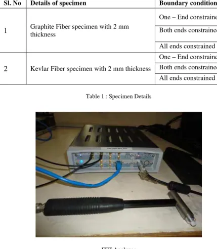
The following equipment shown in fig. below was used to perform an impact test: 1. Impact Hammer with a load cell attached to its head to measure the input force. 2. An Accelerometer to measure the response acceleration at a fixed point and direction. 3. A 4 Channel FFT Analyzer to compute FRF’s.
4. Post-processing Modal software (ME SCOPE) of Vibrant Technology, USA for identifying modal parameters and displaying the mode shapes in animation.
Modeling
Various fibers such as Graphite, Kevlar were chosen to model using Finite Element tool ANSYS. The size of the laminate was fixed at 150x150mm with thickness of 2mm and 3 boundary conditions namely simply supported, Cantilever and both Ends Fixed were simulated. A number of trials were made in the selection of element for meshing of the fibers and analyzed. Finally, SHELL99 appears to yield good results and was chosen to mesh the laminates with different orientation. Stacking sequence of Fibers (O and 90 deg) was done. Initially, coarse mesh was chosen and results were found to be inappropriate, hence model was prepared with fine mesh which improved the results drastically thereby confirming to the convergence criteria.
FFT Analyzer
Frequency response function is a fundamental measurement that isolated the inherent dynamic properties of mechanical structures. FRF is an algorithm for calculating Digital FT in a fast and efficient manner using digital computers. A Fast Fourier Transform is an efficient algorithm to compute the Discrete Fourier Transform (DFT) and its inverse. There are many distinct FFT algorithms involving a wide range of mathematics, from a Simple complex – number arithmetic to group theory and number theory. The input signal is digitized at a high sampling rate, similar to a digitizing oscilloscope. FFT quickly performs a Discrete Fourier Transform which is the practical application of Fourier transforms. With the ability to compute FRF measurements in an FFT analyzer, Impact testing was developed and has become the most popular modal testing method used today.
Table 1 : Specimen Details
Sl. No Details of specimen Boundary conditions
1 Graphite Fiber specimen with 2 mm thickness
One – End constrained
Both ends constrained
All ends constrained
2 Kevlar Fiber specimen with 2 mm thickness
One – End constrained
Both ends constrained
Modal testing of Graphite and Kevlar fibers
Specimen
Designation Graph of Frequency Response Function
Frequency Hz
% Damping
Kevlar – 2mm Cantilever type
i.30.9
ii.49.1
iii.190
iv.291
1.36
1.18
2.92
1.59
Kevlar – 2mm Two ends fixed
i.200
ii.246
iii.380
2.2
1.45
2.59
Kevlar – 2mm Four sides fixed
i.454 ii.869 iii.1.5E+03
Graphite 2mm – Cantilever type
i.46.1 Hz
ii.81 Hz
iii.242 Hz
0.87%
1.21%
2.42%
Graphite 2mm – Two ends fixed
i.386 Hz
ii.415 Hz
iii.548 Hz
iv.851 Hz
0.681 %
0.913 %
1.87 %
1.14 %
Graphite 2mm – All sides fixed
i.535 Hz 2.43 %
Results & Discussions
References
[1] Alexander Bodganovich, K Friedrich, 1994, Initial & Progfressive failure Analysis of Laminated Composite Structures under
Dynamic Loading“, Journal of composite Structures, Vol.27,pp-439 – 456.
[2] A K Noor, Free Vibratios of Multilayered Composite Plates, AIAA J, 11 (1973), pp.1038-1039..
[3] Matsunaga, H, “ Vibration and buckling of multilayered composite beams according to higher order deformation theories”, Journal of
Sound and Vibration, Vol.246, 2001, pp. 47-62.
[4] Jun,L Hongxing, and Rongying S, “ Dynamic Stiffness analysis for free vibrations of axially loaded laminated composite beams”,
composite structures, Vol.84, 2008,pp.87-98.
[5] Kosmatka J B, et.al “Review of Methods to study constrained layer damping”, ASCE Journal of Aerospace Engineering, pp:268-283
[6] Bozhevolnaya E &Frostig Y (2001), “Free vibrations of curved sandwich beams wit a transversely flexible core,” Journal of Sandwich
structures and materials, 3(4): pp-311-342.
[7] [14] Eslimy-Isfahay, S.H.R. and Banerjee, J.R., 1997, “Dynamic response of composite beams with application to aircraft wings”,
Journal of Aircraft, Vol.34, No. 6, pp. 785-791.
[8] Marur, S.R. and Kant, T. (1996). Free Vibration Analysis of Fiber Reinforced Composite Beams Using Higher Order Theories and