Abstract: Automotive Air conditioning (A/C) System is constantly undergoing improvements over the past decades to achieve higher efficiency. Internal heat exchanger (IHX) so far, has not been given much importance to use in automotive A/C systems. The IHX transfers heat from the hot liquid refrigerant from condenser outlet to the suction gas. Although previous researchers have investigated performance of IHX, this study is distinguished from the previous studies with respect to the type, size and material used for IHX construction. This paper describes the way to improve both capacity and energy efficiency of R-134a automotive A/C System. Three different experiments are conducted under steady state condition in a system test bench calorimeter: one without heat exchanger (baseline) and with two different heat exchangers.
The experimental results show that cooling capacity of evaporator increases by 4.84% and 3.17%, Coefficient of performance (COP) increases by 11% and 7.18% and compressor input power reduces by 6.05% and 4.18% with the use of Cu and Al IHX respectively.
Key word: Refrigeration, Heat Transfer, Condenser, Energy, Internal, Exchanger
1. INTRODUCTION
Many technologies are being used for enhancing performance of automotive A/C with R-134a. The IHX technology is probably the simple one, yet it has not being used / given importance for its use on commercial vehicles. The IHX transfers heat from the condenser outlet to the suction gas. The increased subcooling before expansion reduces evaporator inlet enthalpy and thus increases the specific cooling capacity. The increased superheating of gas before compression reduces suction vapour density and increases compressor inlet temperature. The strategy adopted while using IHX technology is to maximize subcooling and minimize superheating. The balance is to be maintained between subcooling and superheating in-order to achieve the efficient performance of A/C system.
Man-Hoe Kim et al. [1] studied the effect of liquid line suction line heat exchanger (LLSL-HX) for residential heat
Avinash. D. Desai, Professor, Department of Mechanical Engineering, Modern College of Engineering, Pune, (India), (ph) +91-20-25507224, [email protected]
S N Sapali, Department of Mechanical Engineering, College of Engineering, Pune, (India), (ph) +91-20-25507224, (M) +91-9423582575,
Parthasarathi. V. Garikipati, Behr India Limited, Pune, India [email protected]
pump with R-22, R-134a, R32/134a, R-407C and R-410 as a refrigerant. However LLSL-HX was not used for car A/C system. D. Boewe et. al [2] used tube in tube type suction line heat exchanger with different tube lengths on transcritical R-744 mobile A/C system. All commercially available components are used but results are taken with different compressors with maximum rpm of 1800. C. W. Bullard et al. [3] presented the results of experimental runs of a prototype of R-744 refrigeration system meant for a compact car. They used LLSL-HX but its effects are not discussed in their paper. S. A. Klein et al. [4] identified new dimensionless parameter attributable to LLSL-HX. They assumed the pressure drop in LLSL-HX to be negligible. Also the test conditions are not well prescribed. J. S. Brown et al. [5] used LLSL-HX in a semi-theoretical simulation model for a transcritical CO2 mobile A/C System. J. Steven Brown et al. [6] carried out comparative analysis of an automotive A/C system operating with CO2 and R-134a, using IHX. Only the simulation results are discussed in this . They did not consider the effect of IHX separately. Marcus P. et al. [7] performed experiments with Fixed Orifice Tube (FOT) and thermostatic expansion valve (TXV). It was concluded that FOT is more beneficial and IHX helped to improve the efficiency of R-134a A/C system. The type of IHX used is not available in this paper. Chao A. Zang et al [8] tested the LLSL-HX on a production vehicle with R-134a A/C system. They concluded that A/C system with LLSL-HX have benefits viz. low compressor discharge pressure, better performance and there was no wet compression. Also their test conditions are not well prescribed. M.S. Kim et al. [9] experimental performance characteristics of azetropes were compared with 12, R-134a,R-22 and R-290 at high temperature heating and cooling conditions including those using liquid-line/suction-line heat exchanger. It was concluded that IHX increased the performance of heat pump; however it was not used for automotive A/C system. Ryan McEnaney et al. [10] presented experimental analysis of the performance of a prototype A/C system based on transcritical operation with R-744 as a refrigerant. IHX was used but its effects are not discussed.
This paper presents the effects of IHX on system performance, power consumption and coefficient of performance (COP). Here two newly built with different materials of IHX are used. Three tests are conducted: one without heat exchanger (i.e. base line) and rest with two different heat exchangers. The wind tunnel results under various operating conditions of vehicle are used as a support
Development of Energy Efficient R-134a
Automotive Air Conditioning System Using
Internal Heat Exchanger
Avinash. D. Desai, S. N. Sapali, Parthasarathi. V. Garikipati
or “real-world” data to design the IHX. Two tube-in tube type internal heat exchangers of unequal lengths but of different materials are designed, fabricated and are tested under steady state conditions on a system test bench calorimeter. The A/C system of a medium size passenger vehicle is used. Keeping all the A/C components same and connecting tubes of actual R-134a, A/C system of a medium size (4 seater) passenger car, experiments are performed using three different IHXs under steady state conditions. This study analyses the effect of IHX with different types and materials on R-134a automotive A/C system which are not yet considered.. The inner tubes of the IHX are having integral fins for enhancing the rate of heat transfer. The design is very compact and weights are very low for both the IHXs. The sizes i.e. length and outer diameter are so selected that the IHX can be easily accommodated in the space available in car bonnet.
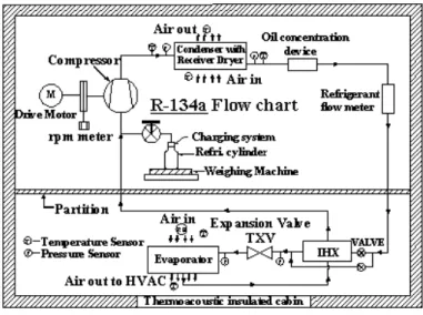
Description of the experimental test bench / calorimeter II DESCRIPTION
The schematic of test bench calorimeter, experimental setup, cycle with IHX and dew point unit (DPU) are shown in Figure 1 and 2 respectively. The calorimeter and DPU helps to maintain the correct temperature and humidity of air as per given test conditions. These combined systems together can be used for testing HVAC modules of automotive small and larger capacity as well as for testing bare components, viz. evaporator, condenser etc. of automotive A/C system, working with refrigerant R-134a. With this test bench, a “real life mounting” of a vehicle refrigerant circuit can be realized. Thus the test bench calorimeter is utilized for testing complete automotive HVAC system under real vehicle conditions.
The entire test bench calorimeter consists of the following sub systems / modules.
1. Closed air loops for supply of conditioned air with two chambers.
2. R-134a refrigerant circuit with compressor drive, speed control device and torque meter.
3. Primary and secondary brine circuits of chiller units to achieve the desired temperatures of air.
4. DPU for controlling humidity of air. 5. V-cones for measurement of air flow rate. 6. Lubricating oil concentration measuring device. 7. Coriolis type flow meter – for refrigerant mass flow
measurement.
8. Power supply system for various drives (AC and DC both).
9. Control Panel and data acquisition system.
10. Condensate measurement system - to determine latent heat load of moist air.
III EXPERIMENTAL APPARATUS
The double chamber layout is as shown in Fig. 1 and Fig. 2. The front evaporator and condenser are to be mounted on the specimen boxes / chambers and for mounting the rear evaporator, the adjustable Table is available.
The components like radial blower with speed control, dew point unit (DPU), dehumidification unit, chiller, various
sensors for measurements of pressures, temperatures, humidity, RPM, torque, mass flow of refrigerant and data acquisition system etc. are located inside the chambers. The airflow rate measuring V-cones with gas tight flap are installed on top of the chambers. The complete system including air measuring sections are covered with noise insulation. The chamber / Calorimeter is connected to the building ventilation system so that the heat load of the chamber / calorimeter can be dissipated to the atmosphere. The water-cooled condenser of the cooling unit i.e. primary brine circuit is equipped with a flow control valve which pumps the water into buffer tank from where the cold water is supplied to secondary circuit-heat exchangers. The heat exchangers in DPU and de-humidifier receive the water (hot / cold) from the secondary circuit, for controlling humidity in the chamber.
The leak detection and recharging system comprising of vacuum pump, Nitrogen cylinder, refrigerant charging and recovery unit, along with lubricating unit and electronic weighing machine are separately available with necessary hoses and connections.
The inlet and outlet air temperature mappings, of evaporator and condenser are considered. Inlet air temperatures are measured by 4 Nos. of calibrated PT-100 sensors and out let air temperatures by 16 number of calibrated of K-type thermocouples in case of an evaporator and condenser. Four no of humidity sensor(s) are used for measurement of humidity of inlet air at evaporator and one humidity sensor is used for measurement of humidity of inlet air to condenser. Thermocouples and pressure transducers at various positions are as shown in Fig 2 measuring the refrigerant temperatures and pressures. All the sensors used for the temperature, pressure, torque meter, RPM and humidity measurement were calibrated prior to their use.
IV. TEST CONDITIONS
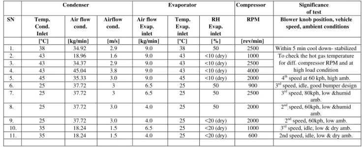
Manufacturers generally have their own test conditions rather than adopting an industry wise standard. This is done in order to be able to compare most recent test data with the historical data from previous testing. It has been a common practice to select the airside test conditions to approximately correspond to the maximum ambient conditions. The Table 1 shows the typical test conditions used during experimental work and their significance. The airflow rates and the compressor rpm are selected corresponding to blower speed knob position and vehicle speed respectively. The various tests conditions are for dry, humid, moderate and high ambient conditions.
TABLEI NOMENCLATURE AND UNITS
Symbol Quantity SI units A Surface area m2
CC/CP Cooling capacity/ cooling performance
kW
COP Coefficient of performance -- DPU Dew point unit --
IHX Internal heat exchanger
TXV Thermostatic expansion valve
V. EXPERIMENTAL PROCEDURE AND MEASUREMENTS
The charge determination test as described below was also conducted to find out exactly how much is the minimum charge required to operate A/C system effectively. This will ensure proper working of A/C system while driving at city and highway traffic conditions and varying ambient. 1. All the components of actual vehicle A/C system viz.
compressor, condenser, TXV, evaporator, etc. were connected using “real world” (vehicle actual piping systems) piping to represent the A/C system under test to be the same as in actual vehicle. The system was instrumented for recording various operating parameters and was wired to data logging system.
2. The system was filled with N2 gas at a pressure of 5 to 5.5 bar and this pressure was maintained for 30 minutes. The system was assured for no leakages. 3. The system was evacuated by nitrogen removal from
the system.
4. Through the refrigerant charging unit, to start with a refrigerant charge of 350g was fed to the system. 5. The system was allowed to stabilize for 10 minutes
after each addition of charge (refrigerant) between 25g-50g till desired values of subcooling and superheating was reached.In the present study we have considered superheating between 5-12K and subcooling up to 10K for charge optimization.
6. Thus correct charge was determined as per above procedure for all the three tests under consideration. 7. As per the tests conditions mentioned in Table 1.
various parameters were varied one by one through PID controller. When one particular parameter is changed, the readings were recorded after system gets stabilized. The pressures, temperatures, humidity and mass flow rates of air and refrigerant were recorded by data logging system at various locations as shown in the experimental setup Fig 2.
8. The mass flow rate of air over evaporator and condenser were measured using V-cones as shown in Fig 1
9. Testing is done for humid, dry, moderate and high ambient conditions. The tests are performed at various test conditions as shown in Table 1. For each test condition, the evaporator performance, COP and compressor input power are found.
10. The oil concentration in the refrigerant was also recorded and found to be maximum of 4.17% which is below tolerable limit of 6%.
11. The compressor input power is measured using the torque meter and its RPM.
12. Three tests / experiments were conducted under steady state conditions on a system test bench calorimeter, one without IHX and two with Cu and Al IHX. The IHX are of concentric tube type. The cold fluid flows in the inner tube and hot fluid in the outer tube (annulus).
VI. RESULTS AND DISCUSSIONS
The experimental data is processed so that the system performance can be evaluated for different operating / test
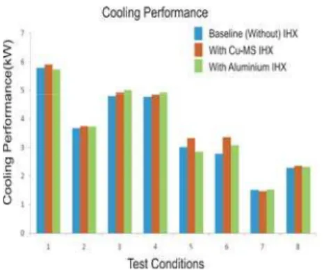
conditions mentioned in Table 1. Fig 3, 4 and 5 show the evaporator cooling performance, gain in COP and reduction in compressor power using Cu and Al IHX.
The IHX are of compact design and both of them have performed their duties as per the design. With their incorporation the average subcooling at TXV is found to be 11.87K and 12.4K in case of Cu and Al IHX respectively. The refrigerant pressure drop in IHX is also very low. Pressure drop on higher side is 3.63kPa and 2.45kPa and for low side it is found to be 1.36 kPa and 4.09 kPa respectively.
The refrigerant superheating at compressor inlet is observed to be 12.17K and 16.12K for Cu and Al IHX respectively. There is significant influence of IHX on R-134a A/C system. It is observed that evaporator performance and COP increase and there is noticeable reduction in power input to the compressor. The oil concentration for base line and Cu and Al IHX tests is also measured and is observed to be 5.02%, 3.93% and 4.65% respectively which is well within the prescribed values.`
VII. CONCLUSIONS
The experiments conducted on system test bench calorimeter and its results have proved that IHX can improve the efficiency of an R– 134a cycle noticeably. The conclusions are as under.
1. The overall improvement in cooling performance of system using Cu and Al IHX is 4.84% and 3.17% respectively.
2. The COP has increased by 11 % and7.18% in case if Cu and Al IHX respectively.
3. The compressor power input is reduced by 6.05% and 4.18 % in case of Cu and Al IHX respectively.
4.The refrigerant subcooling achieved after condenser is 12.23 K and 11.46 K in of Cu and Al IHX respectively. 5. The average refrigerant superheating at compressor inlet
is 12.17K and 16.12K with the use of Cu and Al IHX 6. The refrigerant pressure drop in IHX on higher side is
observed to be 3.63 kPa and 2.45 kPa in case of Cu and Al IHX respectively.
7. The refrigerant pressure drop in IHX on low side found to be 1.36 kPa and 4.09 kPa for Cu and Al IHX respectively.
8. Average refrigerant superheating at evaporator outlet is 5.6K and 7.46K with Cu and Al IHX respectively. 9. The average refrigerant temperature at compressor out let
are 74.34 0C, 88.800 C and 91.090C for base line, Cu and Al IHX respectively.
REFERENCES
[1] Man-Hoe Kim, Piotr A. Domanski, David A. Didion, “Performance of R-22 Alternative Refrigerants in a System with Cross-flow and Counter-flow Heat Exchangers”, NISTIR 5945.
[2] D. Boewe, J. Yin, Y. C. Park, C. W. Bullard and P. S. Hrnjak, “The Role of Suction Line Heat Exchanger in Transcritical R744
[3] C. W. Bullard and P. S. Hrnjak “Transcritical CO2 mobile heat pump and A/C system Experimental and model results” 1999-2000 [4] S. A. Klein, D. T. Reindl, and K. Brownell, “Refrigeration System
Performance using Liquid-Suction Heat Exchangers” Published in the International Journal of Refrigeration, Vol. 23, Part 8, pp. 588-596, 2000.
[5] J.S. Brown, P.A. Domanski, “Semi-Theoretical Simulation Model For A Transcritical Carbon Dioxide Mobile A/C System”, Nist, Pa, 1-11 Pjv2000.
[6] Steven B., Samuel F. Yana-Mottab, Piotr A. D., “Comparitive analysis of an automotive air conditioning systems operating with CO2 and R134a” ELSEVIER International Journal of Refrigeration, pp 19-32, 2002.
[7] Marcus P, Chao Zhang, Tim D. “R134a Suction line heat exchangers in different Configuration of Automotive Air-conditioning Systems” Society of Automotive Engineers, Inc., 2001-01-1694, 2001.
[8] Chao A. Zhang and Brian L. Graham,Ti R. Dickson, “How to Improve Vehicle R134a A/C System Performance with a Liquid Line
Suction Line Heat Exchanger (IHX)”, SAE TECHNICAL PAPER SERIES, 2002-01 -0507.
[9] M.S.Kim, W.J. Mulroy, D.A.Didion “Performance Evaluation of two Azeotropic refrigerant mixtures of HFC-134a with R-290 (Propane) and R-600a (isobutane)” Transaction of the ASME, June 1994. [10] Ryan McEnaney and Pega Hrnjak Clutch cycling Mode of
Compressor Capacity control of Trnscritical R744 systems compared to r134a Systems ”, SAE International 2005-01-2033, 2005
[11] D.Q. Kern “Process heat transfer” Tata Mc Graw Hill publication, 1997 edition, 21st reprint 2010.
[12] M.L.Mathur and F.S.Mehta “Refrigerant and Psychometric properties” Tables and charts, Jain brothers, New Delhi, India
Fig 1. Schematic of Test bench Calorimeter
Fig 3. Cooling performance vs Test conditions
Fig 4. COP vs Test conditions
Fig 5. Compressor Power vs Test conditions
Table 1: Test conditions: system level/calorimeter-bench test with and without IHX
Condenser Evaporator Compressor Significance
of test SN Temp.
Cond. Inlet
Air flow cond.
Airflow cond.
Air flow Evap.
inlet
Temp. Evap. inlet
RH Evap.
inlet
RPM Blower knob position, vehicle
speed, ambient conditions
[ºC] [kg/min] [m/s] [kg/min] [ºC] [%] [rev/min]
1. 38 34.92 2.9 9.0 38 50 2500 Within 5 min cool down- stabilized 2. 43 18.96 1.6 9.0 43 <10 (dry) 1000 To check the hot gas temperature
for diff. compressor RPM and at high load condition 3. 43 34.37 2.9 9.0 43 <10 (dry) 2500
4. 43 45.04 3.8 9.0 43 <10 (dry) 4000
5. 45 35.33 3.0 9.0 45 <10 (dry) 2000 4th speed at 60 kph, high amb. 6. 25 37.72 3 6.5 25 50 900 3rd speed, idle, good bumper design 7. 25 37.72 3 6.5 25 50 2500 3rd speed, 80kph, low &humid
amb.
8. 25 37.72 3.0 4.0 25 50 2000 2nd speed, 60kph, low &humid amb.