Abstract
The tube-array structures coupled both with the fluid and the axial load is focused. In a heat exchanger, the tubes are frequently affected by cold and hot fluid shock waves. Thus, tubes are often found to be vibrated and even to be worn out. This vibration may not only alter the performance of the tubes but also introduce the damage in the heat exchanger. In this work, the dynamic properties of coupled tube-array structures with the axial loads are investigated. Futher, the tube-array structures in a heat exchanger, consisting of periodic cooling tubes are also considered to simulate as a coupled periodic structure system. It is found that each tube of the system is weakly coupled to the adjacent tube via water. By using the Galerkin method, the equations of the coupled system with the fluid effect can be derived. Numerical results reveal that the axial load and fluid effects may influence the dynamic properties of a fluid coupled tube-array structures system of a heat exchanger significantly.
Keywords
Here goes the keywords chosen by the authors, e.g. fatigue, dam-age tolerance, Weibull distribution.
Dynamic Properties of Coupled Tube-Array
Structures with the Axial Loads
1 INTRODUCTION
In the actual engineering applications, the tube-array structures coupled with the fluid are employed frequently to depress the temperature in a heat exchanger system. Especially the heat exchanger is one of the main pieces in safety facilities. Because of the operation with a heat cycling, the strain stresses and axial loads are unavoidable. Axial loads caused by heat strain on the tubes may markedly alter the dynamic behavior of a heat exchanger system. Therefore, dynamic properties of coupled tube-array structures with the axial loads are considered in this work.
The fluid coupled tube-array structures system, a heat exchanger, can be regarded as a weakly coupled periodic structure system. And these weakly coupled systems have attracted some investiga-tors to study, such as [Orgun and Tongue (1994), Huang and Kuang (2001, 2002)]. Such weakly coupling may in turn localize the vibration modes and energy. Moreover, such coupling effect in
Bo-Wun Huang a
Pu-Ping Yu b
Jung-Ge Tseng c
aCheng Shiu University, TAIWAN.
bCheng Shiu University, TAIWAN.
cCheng Shiu University, TAIWAN.
http://dx.doi.org/10.1590/1679-78252474
periodic system may change the natural properties of system significantly. As all of the tubes are assembled periodically, the tubes in a heat exchanger with fluid can be regarded as a periodic system. This work addresses the natural properties, dynamic characteristics, in a heat exchanger with axial load. Most studies as [Kwak, Torii and Nishino (2002), Lorenzini and Giuliani (2002)] focused on the heat or flow problems in a heat exchangers. The dynamic behavior of such tubes or heat exchanger systems has been also studied [Velmurugana and Muralikannanb(2009), Eisinger (1994), Eisinger and Francis (1996), Taylor et al. (1998) ] and they focused on the structure. In actual applications, fluid is always needed in practical heat exchangers. However, this fluid can markedly alter the dynamic properties of the heat exchanger system. And it is insufficient if only aim at the structure of tube. In addition, according to [Yetisir et al. (1998)], the abrasion defects are commonly formed near the center of the tubes due to impact friction and wear during operation in the heat exchanger. Such abrasions are common in heat exchange systems operated under severe conditions, which is the tube impacted by the cold and hot fluid shock flow. Hence, the fluid effects on the dynamics of a heat exchanger system must be examined, and they bring the so-called fluid induced vibration. Investigations such as [Papp and Chen (1994), Tian et al. (2000), Khajehpoura and Azadib (2015)] have paid attentions to the fluid effect on the dynamic behaviors in a system. It was found that the fluid effect changes markedly the dynamic characteristics of a system. Accordingly, the studied as [Chen and Zhu (1994), Chen et al. (1997)] further studied the fluid damping and stiffness of tubes with fluid.
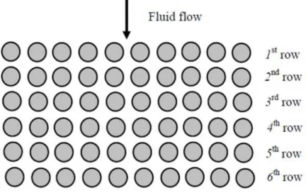
When many Investigators study the fluid induced vibration problems, most of them focused on the single structure, such as a tube or beam, with a fluid. Only a few studies [Elkashlan (1980), Shahab et al. (2012)] focused that the dynamics of a global system with a lot of structures are induced simultaneously and reacted by the fluid, as a heat exchanger system with several tubes except the fluid coupling effect. In this work, the fluid induced vibration in several tubes, because each tube is coupled to the adjacent tube through the fluid, fluid coupling effect can be found in this system. According to the fluid coupling effect, the heat exchanger system can be regard as a periodic system. Dynamics of a periodic system are much different from the general system. Hence, this work focused the fluid induced vibration and coupling effects on the dynamics of a heat exchanger system. In this work, a heat exchanger including 60 tubes and with the fluid effect is focused. With fluid coupling effect, periodically coupled tubes are employed herein to simulate a heat exchanger system. For sim-plicity, the round hollow Euler-Bernoulli beams are used to simulate the tubes in this system. Using Galerkin method, the discrete equation of this system can be derived.
2 EQUATION OF MOTION
denote respectively the transverse flexible deflections of the jth tube in the horizontal plane and in the perpendicular plane, as shown in Fig. 2(b). NR is the number of tubes in each row.
Figure 1: A sketch of a coupled tube-array structures system.
(a) a tube simply supported at both ends
(b) an arrangement of tubes.
Figure 2: A detail diagram of a coupled tube-array structures system.
Equations of the tubes with axial load in this system are displayed as
4 2 2
4 2 2 0, 1, ...,
j j j j
j j j j
u u u u
E I c m P j N
t
r t r
4 2 2
4 2 2 0, 1, ...,
j j j j
j j j j
v v v v
E I c m P j N
t
r t r
(2)
where Ej is the Young's modulus of the material, Ij is the moment of area of the jth tube, P is axial
load. Only the jth tube is considered, while all tubes are the same. Considering the fluid effect, the equations of motion in the jth tube by a heat exchanger are,
4 2 2
4 2 2
j j j j
j j j j j
u u u u
E I c m P g
t
r t r
(3)
4 2 2
4 2 2
j j j j
j j j j j
v v v v
E I c m P h
t
r t r
(4)
j=1,2,3,…,N
where, mj, cj. gj and hj are the mass, damping of the jth tube and fluid forces acting on the tube
respectively. The fluid coupling forces are displayed as follow [Zhu et al. (1997)].
2 2 2
2
2 2
1 1
N N
k k k
j jk jk jk
k t k
u v U u
g R t t t
2
1
N k
jk jk k jk k
k
v
U u v
t
(5)2 2 2
2
2 2
1 1
N N
k k k
j jk jk jk
k t k
u v U u
h R t t t
2
1
N k
jk jk k jk k
k
v
U u v
t
(6)where ρ is fluid density; R is tube radius; t is time; ωt is circular frequency of tube oscillations; U
is flow velocity, and
, , ,
jk jk jk jk
are added fluid-mass coefficients
, , ,
jk jk jk jk
are added fluid-damping coefficients
, , ,
jk jk jk jk
are added fluid-stiffness coefficients
As mentioned previously, the equations above for the jth tube in system can be derived as,
4 2 2 2 2 2
2
4 2 2 2 2
1 1
N N
j j j j k k k k
j j j j jk jk jk jk
k t k
u u u u u v U u v
E I c m P R
t t t
r t r t t
2 1 0 Njk k jk k k
U u v
(7)
4 2 2 2 2 2
2
4 2 2 2 2
1 1
N N
j j j j k k k k
j j j j jk jk jk jk
k t k
v v v v u v U u v
E I c m P R
t t t
r t r t t
2 1 0 Njk k jk k k
U u v
(8)
Corresponding boundary conditions of the jth tube can be given as
0,
0, 0j j
,
, 0j j
u L t v L t (10)
2 2 2 2 0, 0, 0 j ju t v t
r r
(11)
2 2 2 2 , , 0 j ju L t v L t
r r
(12)
For simplicity, this tube system is considered as in stationary fluid. And equations 7 and 8 are rewritten as,
4 2 2 2
2
4 2 2 2
1
N
j j j j k
j j j j jk
k
u u u u u
E I c m P R
t
r t r t
2 2 2 1 0 Nk k k
jk t jk jk
k
v u v
R t t t
(13)4 2 2 2
2
4 2 2 2
1
N
j j j j k
j j j j jk
k
v v v v u
E I c m P R
t
r t r t
2 2 2 1 0 Nk k k
jk t jk jk
k
v u v
R t t t
(14)where jk, jk, , jk jk are added with fluid-damping coefficients. According to [Zhu et al. (1997)],
as the system with the stationary fluid coupling effect, it is observed that the mass coefficients jk, jk
are zero and the fluid-damping coefficients jk, jk are also very small. So, the fluid perturbation is
not considered in this work. Therefore, if these coefficients are neglected, the equations above are rewritten as follow:
4 2 2 2
2 2
4 2 2 2
1 1
0
N N
j j j j k k
j j j j jk t jk
k k
u u u u u u
E I c m P R R
t t
r t r t
(15)4 2 2
4 2 2
j j j j
j j j j
v v v v
E I c m P
t
r t r
+ 2 2 2 2
1 1 0
N N
k k
jk t jk
k k v v R R t t
(16)Without fluid coupling, then the jth tube equations above are de-coupled. In actual applications, it is necessary to consider the fluid coupling effects in a heat exchanger. Because the direction of fluid coupling is u, this u displacement will dominate the dynamic performance of the heat exchanger. Therefore, only the displacement u is considered to facilitate the calculation. For the sake of conven-ience, only the coupling effects of the nearest tubes, i.e., the j-ith, j+1th, j+NRth and j-NRth tubes, are
considered for the jth tube, as Fig. 2(b). Thus, the equation of this heat exchanger with the coupling fluid effect can be derived as follow,
4 2 2 2
2
4 2 2 2
j j j j j
j j j j j j
u u u u u
E I c m P R
t
r t r t
2
2 2
1 1
1 2 1 2 2
R
R j N
j j
j j j j j j N
u
u u
t t t
2 1 2 1 2 R R
j N j j
j j N t j j j j
u u u
R t t t 1
1 R R R R 0
j N j N
j
j j j j N j j N
u u
u
t t t
where NR is the number of tubes in each row and
1 0
j
u
if j 1 0 (18)
1 0
j
u if jnNR1, n=1,2,3, (19)
1 0
j
u
if j 1 N (20)
1 0
j
u
if jnNR, n=1,2,3, (21)
0
R j N
u
if jNR 0 (22)
0
R j N
u
if jNR N (23)
The terms N represent the total numbers of tubes in this heat exchanger, respectively. Dimen-sionless parameters are introduced as follow:
r r
L
and r 0 to 1 (24)
, j
, ,
, j
,j j
u r t v r t u r t v r t
L L
(25)
Equation (17) substituted by dimensionless parameters is shown as follow,
2
4 2 2 2 2 2
1 1
2
1 1
4 2 2 2 2 2 R 2 R
j N
j j j j w j j j
j j j j j j j j N
u
u u u u u u u
c P m
t
r t r t t t t
2 1 1 2 R R
j N w j j
j j N j j j j
u u u
c t t t
1 1 R R R R 0
j N j N
j
j j j j N j j N
u u
u
t t t
(26)
where = 4
EI m L , c=
c
m , 2
P P
mL
, mw
=
2 R m
and cw
= 2 t R m .
For simplicity, the same parameters E, m, L and I are assumed for all tubes. According to [Zhu et al. (1997)], the added fluid-mass coefficients can be employed to study. So, the added fluid-mass coefficients
ii
1.0526
,
ij
0.2845
are considered. By using Galerkin method, the equations
M
V
C V
2
K P H
V 0(27)
where
M
is the mass matrix of the system with a fluid effect,
C
is the damping matrix of the system with a fluid effect,
K
is the stiffness matrix of the system with a fluid effect,
H
is the axial force matrix of the system,
V
is the displacement vector of the system.3 RESULTS AND DISCUSSIONS
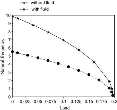
A coupled tube-array structures which has 60 tubes in six rows is employed to study. These dimen-sions; L=381mm (15 inch), pitch-to-diameter 1.35, D=25.4mm (1 inch) and b=0.71mm (0.0279 inch) are considered. This work is to determine the axial load effect on dynamics in a heat exchanger with fluid coupled tube-array structures. Figure 3 displays the natural frequencies of the heat exchanger system with and without fluid effect. Without fluid effect, the natural frequencies of a heat exchanger are the same with figure 3. However, the natural frequencies of this heat exchanger increase as the modes of system are increased when this system with the fluid coupling effect. The effect caused by the fluid mass is that the natural frequencies of the system with fluid to be lower than those without fluid. In actual engineering applications, the heat exchanger is employed to transfer heat for not only water but also for other fluid such as oil. Therefore, the fluid density effect on dynamic characteristics of a heat exchanger is necessary to study. The effect of fluid density on the natural frequencies of a heat exchanger is also considered and presented in Fig. 4. The natural frequencies are depressed as the system with larger fluid density is observed. However, the downward trend of natural frequency of system will be lower when the fluid density is over 3
800 kg / m . It is clear that effect of fluid density
affects slightly as the fluid density is too large.
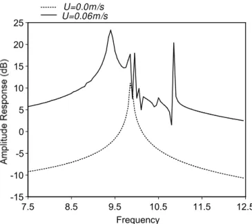
only one peak response is found as the system without a fluid flow. However, when the system with a fluid flow U=0.06 m/s, the several peaks are observed. In addition, the first peak response shifts toward a lower frequency domain, if the system has a fluid flow. Results indicate the fluid flow will change markedly the frequency response of the periodic system.
5 6 7 8 9 10 11
1 2 3 4 5 6 7 8 9 10
mode number
without fluid with fluid
Figure 3: The natural frequencies of the heat exchanger system with and without fluid.
3 3.5 4 4.5 5 5.5 6 6.5 7
0 100 200 300 400 500 600 700 800 900 1000 Fluid density
0 1 2 3 4 5 6 7 8 9 10
0 0.025 0.05 0.075 0.1 0.125 0.15 0.175 0.2
Load
without fluid with fluid
Figure 5: The variation on natural frequencies of a heat exchanger with different axial load.
0.01 0.1 1 10 100
7.5 8.5 9.5 10.5 11.5 12.5
Frequency
without load with load P=0.075N
-15 -10 -5 0 5 10 15 20 25
7.5 8.5 9.5 10.5 11.5 12.5
Frequency
U=0.0m /s U=0.06m /s
Figure 7: The variation in frequency response of a heat exchanger with or without a fluid flow.
4 CONCLUSIONS
Dynamic properties in a heat exchanger system with an axial load is investigated. The following conclusions can be drawn:
(1) The natural properties of a heat exchanger will be decreased when the heat exchanger with an axial load is increased.
(2) Effect of fluid density affects the natural properties of a heat exchanger is observed signifi-cantly.
(3) Result indicates that the critical load of a tube in a heat exchanger is independent upon the fluid density effect. In this work, only stiffness of a tube in a heat exchanger dominates the critical load is found.
Acknowledgments
The authors would like to thank the Ministry of Science and Technology, Taiwan, Republic of China, for financially supporting this research through Grant MOST 103-2221-E-230-008.
References
Eisinger, F.L. (1994). Unusual acoustic vibration of a shell and tube process heat exchanger. ASME, Journal of Pressure Vessel Technology 116(2): 141-149.
Eisinger, F.L., Francis, J.T., Sullivan, R.E. (1996). Prediction of acoustic vibration in steam generator and heat ex-changer tube banks. ASME, Journal of Pressure Vessel Technology 118(2): 221-236.
Elkashlan, M. E. (1980). Tube row and Damping Parameter Effects on Tube-Array Stability. M.S. Thesis, McMaster University.
Huang, B.W., Kuang, J.H. (2002). The Effect of Local Crack on the Dynamic Characteristics of a Rotating Grouped Bladed Disk. IMechE, Journal of Mechanical Engineering Science 216: 447-457.
Khajehpoura, S., Azadib, V. (2015). Vibration suppression of a rotating flexible cantilever pipe conveying fluid using piezoelectric layers. Latin American Journal of Solids and Structures 12(6): 1042-1060.
Kwak, K.M., Torii, K., Nishino, K. (2002). Heat transfer enhancement and pressure-loss reduction for fin-surfaces of in-line tube bundle with a single front row of winglet pairs. JSME, Series B: Fluids and Thermal Engineering 45(4): 910-916.
Longatte, E., Benddjedou, Z., Souli, M. (2003) Methods for numerical study of tube bundle vibrations in cross-flows. Journal of Fluids and Structures 18(5): 513-528.
Lorenzini, E., Giuliani, E. (2002). Dynamics of a tubular heat exchanger with arbitrary flow perturbation. Numerical Heat Transfer 42(8): 833-854.
Orgun, C.O., Tongue, B.H. (1994). Modal localization in Coupled Circular Plates. ASME, Journal of Vibration and Acoustics 116: 286-294.
Papp, L., Chen, S.S. (1994). Turbulence-induced vibration of tube arrays in two-phase flow. ASME, Journal of Pressure Vessel Technology 116(3): 312-316.
Shahab Khushnood et al., (2012). Cross-Flow-Induced-Vibrations in Heat Exchanger Tube Bundles: A Review, 71-128, In: Nuclear Power Plants, InTech (Shanghai).
Taylor, C.E., Pettigrew, M.J., Dickinson, T.J. (1998). Vibration damping in multispan heat exchanger tubes. ASME, Journal of Pressure Vessel Technology 120(3): 283-9.
Tian, M., Cheng, F., Cheng, L., Cao, B.Y. (2000). Experimental study of enhanced heat transfer by flow-induced vibration of elastic tube bundles. Journal of Hydrodynamics 12(3): 103-109.
Velmurugana, R., Muralikannanb, R. (2009). Energy absorption characteristics of annealed steel tubes of various cross sections in static and dynamic loading, Latin American Journal of Solids and Structures 6(6): 358-412.
Yetisir M., McKerrow E., Pettigrew M.J. (1998). Fretting wear damage of heat exchanger tubes: a proposed damage criterion based on tube vibration response. ASME, Journal of Pressure Vessel Technology 120 (3): 297-305.
Zhu, S., Chen, S.S., Cai, Y. (1997). Vibration and Instability of Two Tubes in Cross-Flow. ASME, Journal of Pressure Vessel Technology 119: 142-149.