of Chemical
Engineering
www.abeq.org.br/bjchePrinted in BrazilVol. 34, No. 02, pp. 507 - 530, April - June, 2017 dx.doi.org/10.1590/0104-6632.20170342s20150504
TWO-DIMENSIONAL FLOW OF POWER-LAW
FLUIDS OVER A PAIR OF CYLINDERS IN A
SIDE-BY-SIDE ARRANGEMENT IN THE LAMINAR
REGIME
Saroj K. Panda
*Department of Chemical Engineering, Indian Institute of Technology Delhi New Delhi 110016, India
Tel.: +91 11 2659 6282, fax: +91 11 2658 1120 Email: [email protected]
(Submitted: August 23, 2015; Revised: February 20, 2016; Accepted: March 29, 2016)
Abstract – This manuscript presents the efect of Reynolds number (Re) and proximity of the bodies on the hydrodynamics of low of shear-thinning, Newtonian and shear-thickening luids over a pair of cylinders kept in side-by-side arrangement. Results obtained from the numerical simulations carried out with a combination of diferent parameters in the range of 0.2 ≤ power law index (n) ≤ 1.8, 0.1 ≤ Re ≤ 100 and 1.2 ≤ G (gap between the cylinders/diameter) ≤ 4 have been discussed in details. Analysis of the results gives a clear insight into the complex inluence of Re on streamline patterns, surface pressure proiles, drag and lift coeicients for various luids when the gap between two cylinder is changed.
Keywords: Reynolds number; power-law luids; gap ratio; pressure coeicient; drag-lift.
INTRODUCTION
In day to day life, many systems are encountered where luid low occurs over cylindrical bodies. These ordinary looking systems practically exhibit a rich variety of low phenomena. Diferent low regimes are encountered depending on the velocity of the luid, size of the cylinders and the proximity of the cylinders to the neighboring bodies. Needless to say the fundamental change at the microscopic level is manifested at the macroscopic level, resulting in diferent scaling in the drag and lift forces and coeicients of heat and mass transfer etc. Therefore, the study of low over a circular cylinder has drawn considerable attention over the last few decades. Consequently, over the years, a voluminous body of information on the hydrodynamics of the low of Newtonian luids over a circular cylinder
have been very few studies involving multiple cylinders. It is also readily acknowledged that most high molecular weight and multiphase systems encountered in a broad spectrum of chemical, polymer, food, agro-chemicals, biotechnological and process engineering applications display shear-thinning behavior (Bird et al., 1987; Stefe, 1996; Chhabra and Richardson, 1999). This type of non-Newtonian low behavior is conveniently approximated by the power-law model (Bird et al., 1987; Stefe, 1996; Chhabra and Richardson, 1999). Despite the wide occurrence of shear-thinning behavior in scores of industrial settings, very little is known about the low around a group of cylinders, albeit a reasonable body of knowledge has evolved over the past 10-15 years as far as a single cylinder is concerned. Therefore, the present work is concerned with the low over a two-cylinder assembly in a side-by-side arrangement. In particular, consideration is given to the role of non-Newtonian low characteristics and of the spacing between the two cylinders on the detailed kinematics of the low, as well as on the drag and lift coeicients of each cylinder. It is, however, instructive and useful to briely recount the low of power-law luids past a cylinder and that of Newtonian luids over a side-by-side arrangement of cylinders to facilitate the presentation and discussion of the new results reported herein.
PREVIOUS WORK
As noted earlier, a wide range of literature is available on various aspects of the low over a single cylinder submerged in Newtonian luids (Morgan, 1975; Zdravkovich, 1997, 2003), though there are still unresolved issues, especially at high Reynolds numbers. On the other hand, the analogous literature on the low of power-law luids past a cylinder is not only of recent vintage but is also much less extensive. Some numerical results are now available on hydrodynamics (D’Allessio and Pascal, 1996; Whitney and Rodin, 2001; Chhabra et al., 2004; Bharti et al., 2006, 2007), forced convection heat transfer (Soares et al., 2005; Bharti et al., 2007), and mixed convection heat transfer (Srinivas et al., 2009; Soares et al., 2009; Bouaziz et al., 2010). However, most of these studies are restricted to the steady low regime (Sivakumar et al., 2006), very few studies deal with the low of power-law luids past a cylinder (Patnana et al., 2009), and heat transfer (Patnana et al., 2010; Soares et al., 2010), in the laminar vortex shedding regime. These studies (Patnana et al., 2009, 2010; Soares et al., 2010), signify that all else being equal, shear-thinning behavior enhances the hydrodynamic drag. The efect on drag is particularly striking at low Reynolds number. Besides the aforementioned studies based on the numerical solution of the complete governing equations, some works have been carried out employing standard boundary layer low approximations to obtain approximate expressions for skin friction and Nusselt number (Khan
et al., 2006). A few experimental studies on low of non-Newtonian luids past a cylinder have also been reported (Coelho and Pinho, 2003), which elucidate the roles of visco-elastic and shear-thinning behavior on the vortex shedding characteristics. Since the luids used in most of the studies display both elastic and shear-thinning characteristics, it is diicult to delineate their individual contributions unless the special low classiication criteria are used (Astarita, 1979; Thompson and Mendes, 2005). Therefore, possibilities of detailed comparison between the prediction and experimental observation are excluded.
The low over two-cylinders of equal size arranged in diferent conigurations represents the simplest possible model to study the hydrodynamics of the low over a group of cylinders. In this case, the low is inluenced not only by the value of Reynolds number (Williamson, 1985; Meneghini et al., 2001; Chitanya and Dhiman, 2012), but also by the center-to-center distance between the two cylinders (Bearman and Wadcock, 1973; Williamson, 1985; Chitanya and Dhiman, 2012). The low characteristic also changes depending on the geometrical coniguration of cylinders such as side-by-side (Bearman and Wadcock, 1973; Kang, 2003; Chitanya and Dhiman, 2012) and tandem (Meneghini et al., 2001; Juncu, 2007(2); Patil et al., 2008).
side-by-side arrangement are studied numerically, over a wide range of Reynolds number from 0.1-100. In addition to the efect of Reynolds number, the efects of power-law index and the gap between the two cylinders on pressure coeicients, drag and lift coeicients are analyzed in detail. The behavior of shear-thinning luid has also been compared with that of the Newtonian and shear-thickening luids under a few selected conditions.
PROBLEM STATEMENT AND GOVERNING EQUATIONS
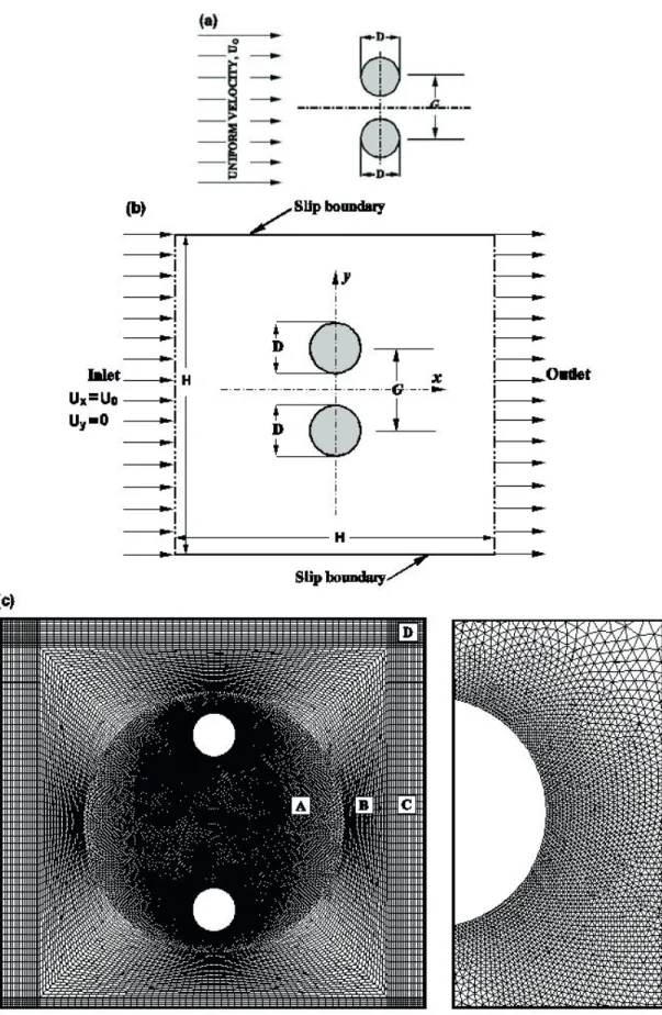
Physical arrangement of the cylinders and the low are schematically illustrated in Figure 1 (a). The circular cylinders shown in this igure are ininitely long in the z-direction and are of equal radius R and diameter D. The low considered here is two-dimensional, incompressible, with uniform inlet velocity Uo. Based on the available literature (Kang, 2003; Sivakumar et al., 2006), low for both Newtonian and power-law luids is initially assumed to be steady up to Re = 40 and unsteady for Re > 40. To ascertain that the low is indeed steady up to Re = 40, over the range of conditions used here, a few preliminary time-dependent simulations for extreme values of parameters (Re, G, n) are performed. Also unsteady calculations are carried out for high Reynolds number (Re = 100) to see the efect of all parameters (Re, G, n) in the power-law regime. Since it is not possible to simulate an unconined low numerically, it is customary to introduce an artiicial domain in the form of a box as shown in Figure 1 (b). In the igure, the cylinders are placed inside a square of size H, with a gap of G in such a way that the mid-point between the two cylinders coincides with the center of the box. The value of His chosen in such a manner that the study is carried out with modest computational resources without inluencing the low ield. The results obtained from the time dependent study indicate that the low is steady in the range Re = 0.1 - 40 and is in agreement with the available literature (Kang, 2003; Sivakumar et al., 2006). The low becomes unsteady in the range Re = 40 - 100. To characterize the low of both Newtonian and power-law luid, in both steady and unsteady domain, the continuity and momentum equations are solved. The governing equations in their dimensionless form are given below.
Continuity equations in cartesian form:
Momentum equations in cartesian form for the x- and y- directions:
x-momentum equation
y-momentum equation
For power-law luids, the extra stress tensor τij is related to the rate of deformation tensor (εij) and is expressed as:
where the rate of deformation tensor is given by:
and the viscosity, η, for a power-law luid is given by
where n is the power-law index. While n =1 corresponds to the Newtonian behavior, n < 1 denotes the shear-thinning behavior of luid. I2 is the second invariant of the rate of deformation tensor and expressed as (Bird et al., 2002):
The physically realistic boundary conditions for this low are written as follows:
(i) At the inlet plane: The uniform low in x-direction is prescribed, i.e.,
(ii) The top and bottom walls are assumed to be slip boundaries so that there is no dissipation at these walls. In mathematical terms, these are expressed as:
(iii) On the surface of the solid cylinders: The standard no-slip boundary condition is used, i.e.,
(iv) At the exit plane: The default outlow boundary condition option in FLUENT (a zero difusion lux for all low variables) was used in this work. This choice implies that the conditions of the outlow plane are extrapolated from within the domain and this extrapolation procedure has negligible inluence on
0
y xU
U
x
y
∂
∂ +
=
∂
∂
(
)
(
)
1Re
x y yx
x x
x U U U U xx
U P
t x y x x y
τ τ ∂ ∂ ∂ ∂ + + = −∂ + ∂ + ∂ ∂ ∂ ∂ ∂ ∂
(
) (
)
1Re x y y y
y U U U U xy yy
U P
t x y y x y
τ τ ∂ ∂ ∂ + + = −∂ + ∂ +∂ ∂ ∂ ∂ ∂ ∂ ∂
2
ij ijτ
=
ηε
1
2
j i ij j iU
U
x
x
ε
=
∂
∂
+
∂
∂
( )
12 2
2
n
m
I
η
=
−2 2 2 2
2 ij
.
ji xx xy yx yyi j
I
=
∑∑
ε ε
=
ε
+
ε
+
ε
+
ε
0 x
U
=
U
U
y=
0
0 ;
0
x y
U
U
y
∂
=
=
∂
0
xU
=
0
xU
x
∂
=
∂
;0
yU
x
∂
=
∂
the upstream low conditions. Furthermore, the scheme used by FLUENT updates the outlow velocity and pressure in a manner that is consistent with the fully developed low assumption, when there is no area change at the outlow boundary. However, the gradients in the cross-stream direction may still exist at the outlow boundary. This is similar to the homogeneous Neumann condition, that is,
The numerical solution of the governing equations (1), (2) and (3), together with the aforementioned boundary conditions, maps the low domain in terms of the primitive variables, namely, Ux, Uy and P. These variables are post-processed to evaluate the derived quantities such as stream function, surface pressure coeicients, drag and lift coeicients as functions of the pertinent governing parameters. At this juncture, it is appropriate to introduce the deinitions of some of these, as well as the other relevant parameters.
In this work, the free stream velocity, U0, and diameter of the cylinder, D, are used as scaling variables. Thus, the pressure is scaled using ρU02 , stress components using
0 n U m D
, time with 0
D
U . Furthermore, the low is governed
by three dimensionless groups, namely, the Reynolds number (Re), power-law index (n), and the non-dimensional gap spacing (G).
Reynolds number (Re) is expressed as
Re = 2 0 n n
U
D
m
ρ
−and the non-dimensional gap spacing is expressed as
Total drag (CD), pressure drag (CDP) and friction drag (CDF) coeicients are written as
where CD is the drag force in the direction of low exerted on the cylinder per unit length. It is also customary to split the total drag force into two components arising from the shear and pressure forces. The parameters that represent
the shear force and pressure components are referred to as the friction drag coeicient (CDF) and pressure drag coeicient (CDP), respectively.
The non-dimensional parameter that is used to represent the lift is referred to as the lift coeicient (CL) and given as:
where FL is the lift force acting in the y-direction on the cylinder per unit length. The lift force also has two components, i.e., shear and pressure. These components are represented by two dimensionless parameters known as the pressure lift coeicient (CLP) and friction lift coeicient (CLF).
To get the information about the pressure distribution on the surface of the cylinders, the surface pressure coeicient (CP) is calculated and expressed as:
where p is the local pressure at a point on the surface of the cylinder and P∞ is its reference value far away from the cylinder.
In this work, the vortex shedding frequency (f) is calculated for the unsteady low regime (Re = 100) from the time history of the lift coeicient (CL). The time period (T) has been calculated based on 10 constant periodic cycles.
NUMERICAL SOLUTION METHOD
In this study, the ield equations are solved using FLUENT, whereas a third-party software is used for creating a suitable solution mesh. Diferent regions of the grid structure used for the present study are shown in Figure 1(c). Fine unstructured triangular cells are generated in the region close to the cylinder (region A) where the gradients are expected to be steep. In all other regions (B, C and D), quadrilateral cells are used and the grid is stretched from ine to coarse using the ‘successive ratio’ stretching function.
The two-dimensional, laminar, segregated solver is used to solve the incompressible low on the collocated grid arrangement. Both steady and unsteady solvers are used in this study. The detailed description of the numerical solution procedure is available in our earlier papers (Panda and Chhabra, 2010, 2011). To ascertain the prediction of the solver at high Reynolds number, low patterns of both Newtonian and power-law luids are obtained and can be validated using the results reported by Kang (2003). For discretizing the convective terms in the momentum equations a secondorder upwindscheme is used, whereas semi-implicit method for the pressure linked equations
g
G
D
=
2 02
D DF
C
U D
ρ
=
, 2 02
DPDP P x
S
F
C
C n dS
U D
ρ
=
=
∫
and(
)
1 2 02
2
Re
n DF DF s SF
C
n dS
U D
τ
Table 1. Physical properties of the luid used
Re ρ (Kg/m3) m (Kg/m-s)
n = 0.2 n = 0.4 n = 0.6 n = 0.8 n = 1 n = 1.2
0.1 0.1 0.01584 0.02511 0.03981 0.06309 0.1 0.15848
0.2 0.2 0.01584 0.02511 0.03981 0.06309 0.1 0.15848
0.5 0.5 0.01584 0.02511 0.03981 0.06309 0.1 0.15848
1 1 0.01584 0.02511 0.03981 0.06309 0.1 0.15848
2 2 0.01584 0.02511 0.03981 0.06309 0.1 0.15848
5 5 0.01584 0.02511 0.03981 0.06309 0.1 0.15848
10 10 0.01584 0.02511 0.03981 0.06309 0.1 0.15848
20 20 0.01584 0.02511 0.03981 0.06309 0.1 0.15848
30 30 0.01584 0.02511 0.03981 0.06309 0.1 0.15848
40 40 0.01584 0.02511 0.03981 0.06309 0.1 0.15848
100 100 0.01584 0.02511 0.03981 0.06309 0.1 0.15848
Table 2. Selection of optimum domain at Re = 0.1
H/D
Re = 0.1, n = 1, G = 4
Upper Cylinder Lower Cylinder
CDP CD CLP CL CDP CD CLP CL
220 21.6440 43.7499 1.9171 3.8090 21.6429 43.7506 -1.9194 -3.8081
240 21.3989 43.2549 1.8931 3.7618 21.3979 43.2556 -1.8954 -3.7610
260 21.3984 43.2546 1.8924 3.7612 21.3981 43.2558 -1.8955 -3.7625
H/D
Re = 0.1, n = 0.2, G = 4
Upper Cylinder Lower Cylinder
CDP CD CLP CL CDP CD CLP CL
220 183.551 262.335 0.6632 -0.8828 183.541 262.325 0.6312 0.8464
240 183.581 262.378 -0.6704 -0.8927 183.571 262.369 0.6375 0.8553
260 183.542 262.338 -0.6724 -0.8962 183.568 262.364 0.6324 0.8592
Table 3. Selection of optimum domain at Re = 5
H/D
Re = 5, n = 1, G = 4
Upper Cylinder Lower Cylinder
CDP CD CLP CL CDP CD CLP CL
100 2.2058 4.2072 0.3475 0.6494 2.2058 4.2072 -0.3477 -0.6491
120 2.1853 4.1696 0.3464 0.6475 2.1853 4.1697 -0.3466 -0.6472
180 2.1838 4.1706 0.3458 0.6470 2.1855 4.1710 -0.3465 -0.6485
H/D
Re = 5, n = 0.2, G = 4
Upper Cylinder Lower Cylinder
CDP CD CLP CL CDP CD CLP CL
100 4.2432 5.8273 -0.021 -0.032 4.2433 5.8275 0.0201 0.0308
120 4.2447 5.8290 -0.021 -0.032 4.2448 5.8293 0.0200 0.0308
180 4.2454 5.8297 -0.021 -0.032 4.2454 5.8299 0.0201 0.0309
(SIMPLE) scheme is used for solving the pressure-velocity coupling. A time-integration second order implicit scheme is used with time step size (Δt) of 0.01. A through time dependent study is carried out to arrive at an optimum value of Δt. The physical properties of the low are given as inputusing constant density and non-Newtonian power-law viscosity modules. Minimum and maximum viscosities of the luid used in the simulations are 0 and 1e20 Kg/m-s, respectively. The physical properties such as ρ, m, n used for this work are given in Table 1. The input values of these physical properties and kinematic parameters such as D, U0, Ω, etc. are of no consequence as the inal results are reported in a dimensionless form. It must be noted here that the present simulations do not consider the efect of
gravitational force on the low. FLUENT solves the system of algebraic equations using the Gauss-Siedel (G-S) point-by-point iterative method in conjunction with the algebraic multi-grid (AMG) method solver. The use of the AMG scheme greatly reduces the number of iterations (thereby accelerating convergence) and thus economizing the CPU time required to obtain a converged solution, particularly when the model contains a large number of control volumes. For the present study, a relative convergence criterion of 10-8 is used for the residuals of the continuity
CHOICE OF NUMERICAL PARAMETERS
It is well known that the reliability and accuracy of the numerical results are dependent on a prudent choice of the numerical parameters, namely, the optimal domain size (H), grid characteristics (number of cells on the surface of the cylinder, grid spacing, stretching, etc.) and to some extent by the convergence criterion, etc. (Roache, 1994; Sivakumar et al., 2007; Patil et al., 2008; Sahu et al., 2009). In this work, the values of these parameters have been selected after extensive exploration by varying their values within 100 ≤ H / D ≤ 300. Due to the slow spatial decay of the velocity ield at low Reynolds numbers, the
required domain size decreases with increasing Reynolds number. For this purpose, the values of Re = 0.1 and 5 are taken to be representative of the low and high Reynolds number region. The results summarized in Tables 2 and 3 show the inluence of (H/D) on CD, CDP, CL and CLP for two diferent values of Reynolds number (Re = 0.1 and 5), two extreme values of power-law index (n = 1 and 0.2) and for G = 4. From the analysis of these results obtained from the domain independent study, (H / D) = 240 is chosen for Re < 5 whereas (H / D) = 120 is selected for Re ≥ 5 studies to nullify the domain efect. It must be noted here that the domain used in this study is much larger than that used by others (Kang, 2003).
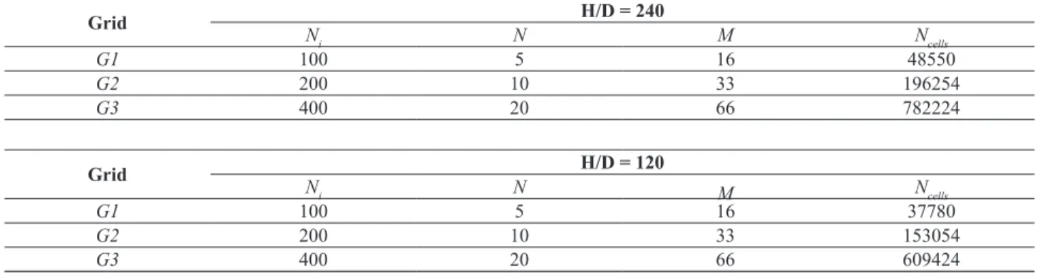
Table 4. Details of grids used for the grid independence study
Grid H/D = 240
Ni N M Ncells
G1 100 5 16 48550
G2 200 10 33 196254
G3 400 20 66 782224
Grid H/D = 120
Ni N M Ncells
G1 100 5 16 37780
G2 200 10 33 153054
G3 400 20 66 609424
Ni = Number of points on the surface of the cylinder N = Number of points in the 1st sub domain M = Number of points in the 2nd sub domain
Similarly, an optimal grid is used to resolve the thin boundary layers and steep gradients near the cylinders without being prohibitively computationally intensive. To arrive at the choice of an optimal grid, the relative performances of the three grids were studied in details. Each grid was characterized in terms of the number of points (Ni) on the surface of cylinder and the value of (δ / D)near the cylinder, which are summarized in Table 4. A typical grid is shown in Figure 1(c). Tables 5 and 6 summarize the relative performance of each grid in terms of CD, CDP, CL and CLP. From the detailed analysis of these results, it is noted that very little is gained in terms of accuracy by
moving from G2 to G3, however, the CPU time required for G3 is many fold higher than that needed for G2 to satisfy the same criterion of convergence. Therefore, grid G2 that denotes a good compromise between the accuracy and computational efort is chosen for the present study. Using the grid G2 and optimized domains, the two dimensional steady and unsteady low computations were carried out. The parameters used for the present study are as follows: Reynolds number, Re = 0.1, 0.2, 0.5, 1, 2, 5, 10, 20, 30, 40 and 100
Power-law index, n = 0.2, 0.4, 0.6, 0.8 and 1 Gap spacing, G = 1.2, 1.7, 2, 2.5 and 4
Table 5. Efect of grid details on the results at Re = 0.1 (H/D = 240)
Grid
Re = 0.1, n = 1, G = 4
Upper Cylinder Lower Cylinder
CDP CD CLP CL CDP CD CLP CL
G1 20.0215 42.2026 1.8351 3.3564 20.0225 42.2046 -1.8342 -3.3586
G2 21.3989 43.2549 1.8931 3.7618 21.3979 43.2556 -1.8954 -3.7610
G3 21.4007 43.2452 1.9020 3.7681 21.3906 43.2451 -1.8920 -3.7583
Grid
Re = 0.1, n = 0.2, G = 4
Upper Cylinder Lower Cylinder
CDP CD CLP CL CDP CD CLP CL
G1 179.338 255.226 -0.8358 -1.0313 179.312 255.182 0.8298 1.0223
G2 183.581 262.378 -0.6704 -0.8927 183.571 262.369 0.6375 0.8553
It is to be noted here that, for comparison of low behavior of shear thinning luid with that of the shear thickening luid, some additional simulations have been carried out using power-law index 1.2, 1.6 and 1.8 at selected Reynolds numbers (0.1 and 40) at gap spacings of 1.2 and 4.
RESULTS AND DISCUSSION
Validation of Results
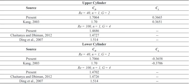
Prior to presenting new results of any numerical study, it is necessary to validate the numerical solution procedure to ascertain the accuracy and reliability of the results. Towards this end, some of the results obtained from this numerical analysis are presented in Table 6 along with the data reported by Kang (2003), Ding et al. (2007) and Chaitanya and Dhiman (2012) under similar conditions. Comparison of the data given in Table 7 signiies that the results obtained from the present study are in good agreement with the results reported by other researchers.
The small deviations in values can be attributed to the diferent grid sizes, solution methodologies, size and shape of domain, convergence criterion, etc. (Roache, 1994) chosen for simulations.
Aside from the aforementioned comparisons, the credibility of the numerical solution methodology employed herein is veriied by studying the low of Newtonian and power-law luids in the standard lid driven square cavity separately and thereafter comparing the results with available information (Ghia et al., 1982; Neofytou, 2005). The centerline velocities obtained from the present standard lid driven square cavity are found to be within ±2% of the corresponding Newtonian results (Ghia et al., 1982), and within ±2.5% for power-law luids as reported by Neofytou (2005). Agreement of the results reported here with those reported by others demonstrates the credibility of the numerical solution methodology used for the present study. Based on the above mentioned comparison and past experience, the present results for the two cylinder coniguration in power-law luids are believed to be reliable to within ±1-2%.
Table 6. Efect of grid details on the results at Re = 5 (H/D = 120)
Grid
Re = 5, n = 1, G = 4
Upper Cylinder Lower Cylinder
CDP CD CLP CL CDP CD CLP CL
G1 2.1033 4.1561 0.3235 0.6356 2.1014 4.1512 -0.3227 -0.6438
G2 2.1853 4.1696 0.3464 0.6475 2.1853 4.1697 -0.3466 -0.6472
G3 2.1844 4.1633 0.3467 0.6488 2.1849 4.1658 -0.3459 -0.6483
Grid
Re = 5, n = 0.2, G = 4
Upper Cylinder Lower Cylinder
CDP CD CLP CL CDP CD CLP CL
G1 4.1291 5.8207 -0.035 -0.043 4.1321 5.8224 0.0355 0.0435
G2 4.2447 5.8290 -0.021 -0.032 4.2448 5.8293 0.0200 0.0308
G3 4.2431 5.8278 -0.020 -0.031 4.2444 5.8294 -0.0200 -0.0310
Table 7. Comparison between the present and literature values for Re = 100 and 40; G = 2 and 4; n = 1
Upper Cylinder
Source CD CL
Re = 40, n = 1, G = 2
Present 1.7064 0.3665
Kang, 2003 1.70 0.3651
Re = 100, n = 1, G = 4
Present 1.4686
--Chaitanya and Dhiman, 2012 1.4727
--Ding et al., 2007 1.514
--Lower Cylinder
Source C
D CL
Re = 40, n = 1, G = 2
Present 1.7066 -0.3658
Kang, 2003 1.70 -0.3706
Re = 100, n = 1, G = 4
Present 1.4702
--Chaitanya and Dhiman, 2012 1.4726
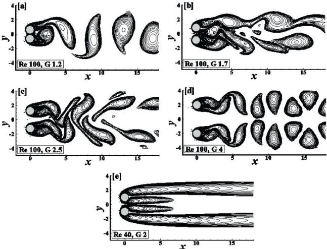
--Figure 2. Vorticity contours for diferent wake patterns (a) single bluf-body pattern (Re=100, G=1.2); (b) lip-lopping pattern (Re=100, G=1.7); (c) in-phase-synchronized pattern (Re=100, G=2.5); (d) anti-phase- synchronized pattern (Re=100, G=4); (e) steady pattern (Re=40, G=2).
In Figure 2, only the vorticity contours for Re = 40 and 100 (for Newtonian luids) for diferent gap ratios are presented to validate the low patterns shown by Kang (2003) in their study. The patterns are (a) single bluf-body pattern (Re = 100, G = 1.2), (b) lip-lopping pattern (Re = 100, G = 1.7), (c) in-phase-synchronized pattern (Re = 100, G = 2.5), (d) anti-phase-synchronized pattern (Re = 100, G = 4) and (e) steady pattern (Re = 40, G = 2). The low patterns presented here are in good agreement with those of Kang (2003). As observed, the wake patterns are highly dependent on the gap between the two cylinders. At G = 1.2, both cylinders act like a single body and vortices are formed periodically at both sides of the cylinders. The low through the narrow gap between the cylinders has no real efect on the wake region, so complete suppression of narrow vortices occurs between the cylinders. This low pattern is called ‘single bluf-body pattern’. Upon increasing the gap from 1.2 to 1.7 (see Figure 2(b)), the low encountered between the cylinders experiences a drag force from the cylinder surface and vortex shedding occurs in a highly irregular fashion. Such a low structure is called ‘lip-lopping pattern’ as suggested by Kang (2003). When
the gap is increased to 2.5, the vortices generated from the cylinders merge with each other at the initial stage, but separate far away from the cylinder in the downstream. This low pattern is known as ‘in-phase-synchronized pattern’. With a high gap ratio (at G = 4), the wakes formed are periodic in nature and formed separately from each cylinder. According to Kang (2003), the same drag coeicients are observed for both the cylinders and lift coeicients occur in anti-phase. So the pattern is referred to as an ‘anti-phase-synchronized’ pattern. At Re = 40 (G = 2), the low is steady and symmetric about the mid-plane. No vortex shedding occurs in this case and the pattern is named as ‘steady pattern’.
Detailed Flow Characteristics
Streamline Proiles
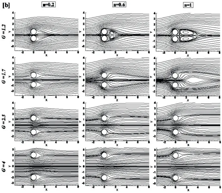
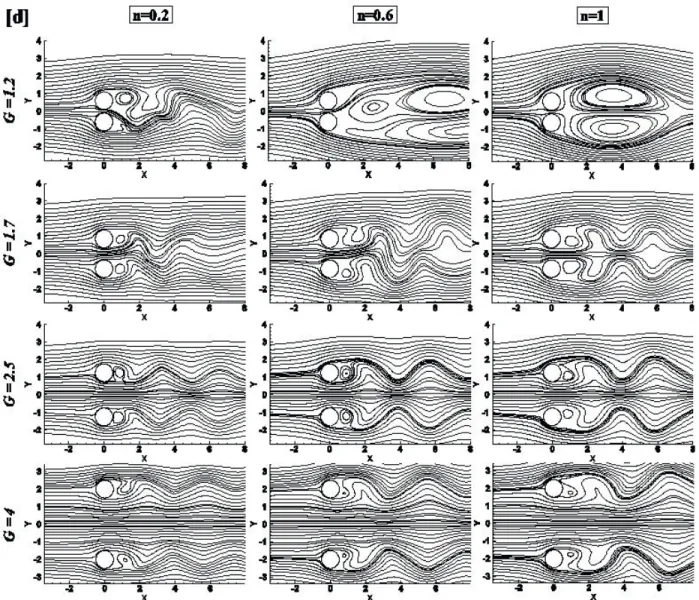
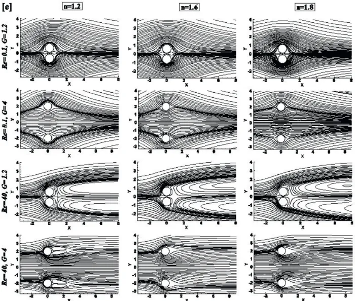
Figure 3 shows the results elucidating the inluence of Re, G and n on the streamlines in the vicinity of the cylinder. While Figure 3 (a) - (d) represent the streamlines obtained for Newtonian and shear-thinning luids, Figure 3 (e) shows streamlines for shear-thickening luid at selected conditions. For the range of Reynolds number used here, the low is known to be steady (0.1 ≤ Re ≤ 40) and unsteady (Re = 100) for all values of the power-law index (n) and gap (G) between the two cylinders.
For shear-thinning luids, the low ield is seen to be symmetric about the mid-plane at low Re (≤ 0.1) for all values of G. This is due to the fact that the viscous forces outweigh the inertial forces and a luid element is able to follow the surface of the cylinders under these conditions. For ixed values of n and G with gradual increasing of Re, the low ield gets detached from the surface of the
cylinder, which leads to the formation of the wake region in the rear end of the cylinder. This marks the formation of a pair of standing vortices at both cylinders, which grow independently with increasing value of Re, until Re attains a critical value.
For G = 1.2, n = 0.2, at very low Re, i.e., at 0.1 the streamlines show symmetry about the mid-plane and follow a very close path. When Re is increased beyond 10 no wake formation is observed. Finally, the low ield is detached from the cylinder surface at Re = 40 and 100, and a pair of vortices are formed at each cylinder.
At G = 1.2, with increasing power-law index from 0.2 to 1, no vortices are found at Re = 0.1. At this condition, even for shear-thickening luid with n = 1.2 - 1.8 not much diference is observed in streamline proiles (Figure 3(e)). The streamline proile obtained for low gap ration and low value of Re resemble the streamline obtained for a single
bluf body irrespective of power-law index. When Re is increased to 10, vortices start forming at n = 0. Upon increasing the value of Re to 40, the wakes formed at n = 0.6 become larger in size compared to that formed at Re = 10. Simultaneous comparison of streamline proiles shown in Figure. 3 (c) and 3 (e) for G = 1.2 and Re = 40 shows that the size of the wake grows with an increase in the value of n, irrespective of the nature of the luid (i.e., shear-thinning, Newtonian or shear-thickening). When Re is increased to 100, vortices become unstable at the rear region of the cylinder for n = 0.2 to 0.6. However, when n is increased to 1, vertices become stable and become symmetric about the mid plane with the formation of wakes.
It has already been mentioned that at G =1.2 for low Re the streamline proiles obtained resemble the streamline proile obtained for a single bluf body irrespective of the power law index. When G is increased to little higher
value, the streamline proiles follow a wider path, yet the low ield evoked by one cylinder is never independent of the other. At very high value of G, each cylinder behaves like an individual bluf body and creates a low pattern without any inluence of its neighboring cylinder. The shear thinning luid with n = 0.2 can be an example to explain these phenomena. For G = 1.2 and at Re = 0 .1, the low proile almost resembles the low proile evoked by a single bluf body. When the G is increased to 2.5 or 4, the streamline proile evoked by each cylinder resembles the streamline proile obtained for low over a single cylinder. However, when G = 1.7, the streamline proile no longer resembles the streamline proile of a bluf body, neither does it look similar to that obtained at G = 2.5 or 4. The proile here is clearly inluenced by the proximity of the cylinders. For the same luid with n = 0.2, if the Re is increased from 0.1 to 40 and above, the streamline proile
Figure 3. (c)Streamline contours for Re=10 at diferent G and n obtained at G = 2.5 no longer looks like the streamline proiles of two individual cylinders. This implies that the streamline proiles are also inluenced by Re. For instance, the velocity ield decays rapidly in shear-thinning luids, therefore very little interference is seen even up to Re = 10 and/or G = 1.2. On the other hand, the proximity of the two cylinders causes a boundary of the streamlines on the inner side of the cylinders, whereas that on the other side is seen to be inluenced very little by the close proximity of the two cylinders. The luid in the throat region experiences acceleration during the course of its passage through the nip region. The efect progressively diminishes with the increasing value of G. However, this asymmetry in the low ield gives rise to lift forces (in the y-direction) exerted on each cylinder. This asymmetry is seen to be present at all values of the Reynolds number, thereby leading to the formation of unequal sized standing vortices once the Reynolds number exceeds a critical value.
Surface Pressure Proiles
Figures 4 (a) and (b) show representative surface pressure proiles for both the upper and lower cylinders for a range of combinations of Re, G and n. Pressure proiles are shown over the entire surface (00 ≤ θ ≤ 3600) for both
Figure 3. (d)Streamline contours for Re=100 at diferent G and n At Re = 100, increasing G, the pressure decreases at the front region of both the cylinders. With increasing G, the efect of n decreases on the values of CP for Re = 40 and 100. The pressure is negative over most of the cases and this comes from diferent scaling of viscous and inertial forces on velocity and the power-law index.
Macroscopic Characteristics
The macroscopic characteristics of the low are often presented by drag and lift coeicients. These characteristics in the steady state domain are discussed in the following sections.
Pressure Drag (CDP) and Friction Drag (CDF) Coeicients
Figure 5 (a) and (b) illustrate the inluences of Reynolds number (Re), power-law index (n) and non-dimensional gap (G) on pressure drag (CDP) and friction
Figure 3. (e)Streamline contours for Re = 0.1, 40 at G = 1.2, 4 and n = 1.2, 1.6 and 1.8 luid has higher friction drag coeicient than that of
shear-thinning luids. The similar trend in the low pattern is noted for all values of G. To further analyze the behavior, the variations of (CDP / CDF) at diferent values of n, Re, G are illustrated in Figure 6. From this igure, it can be seen that at high Reynolds number range the pressure drag (CDP) is always higher than the friction drag (CDF) for both Newtonian as well as power law luids at the same value of Re and G.
Total Drag (CD) Coeicients
The dependence of the total drag coeicients, CD (= CDP +CDF), on the Reynolds number (Re) and the power-law index (n) for diferent gap ratios (G) is shown in Figure 7 (a). The value of total drag coeicient is approximately the same for both the cylinders. Therefore, a single igure (Figure 7) is used to represent the efect of drag coeicient. It is seen that, for constant n and G, an increase in Re
decreasesCD.CD becomes minimum at higher Re (Re = 40) for all the luids over the entire range of G. The plot of CD vs Re (Figure 7 (a)) has a striking similarity with the plot of CDP vs Re (Figure 5 (a)). This similarity in the trend is attributed to the dominance of pressure drag coeicient over its counterpart friction drag coeicient over the entire studied range of Re, n and G. With an increase in n from 0.2 to 1, the CD continuously decreases for all the conditions except in the range Re = 15-40 with G = 1.7- 4.
Figure 4 (a). Representative pressure proiles on the surface of the upper cylinder (hereafter, this point is referred to as the critical value of
G (Gc)). A further increase in the value of G beyond this critical value (Gc) does not inluence the value of CD. From the plots given for Re = 10 in Figure 7 (b), it can be noted that Gcdepends on n. The value of the Gc for the power-law luid with the smallest value of n is lower than that of the other luids. On the other hand, at Re = 40, with an
Figure 4 (b). Representative pressure proiles on the surface of the lower cylinder increasing G. A comparison of the plots shown in Figure 7
(b) also indicates that at low Re, the CD of shear-thinning luid is higher than that of the Newtonian luids. The value of CD further decreases when shear-thickening luid is used instead of Newtonian luid (Figure 8). However, as the value of Re (especially above Re =10) increases the CD of shear-thinning luid decreases and becomes less than that of a Newtonian luid. In this regime, the value
Figure 6. Variation of total lift coeicient (CDP/ CDF)with Reynolds number (Re)
Since at very high gap ratio (G = 4) each cylinder almost behaves like an individual bluf body and creates a low pattern without any inluence of its neighboring cylinder, the comparison between CD values obtained for twin cylinders with that obtained for an isolated cylinder is inevitable. Therefore, CD values of the upper cylinder of the present case have been compared against the CD values of an isolated cylinder (Panda and Chhabra, 2010) at some selected Re and n for gap ratio 4 (see Table 8). From the table it can be seen that there exists a diference in values of CD for same values of Re and n. This diference in CD values signiies the presence of some inluence of the neighboring cylinder on the hydrodynamics, even though the streamline proile evoked by each cylinder resembles the streamline proile obtained for low over a single cylinder.
Total Lift (CL) Coeicients
Figure 9 shows the variation of the total lift coeicient with Reynolds number (Re) at diferent gap ratios (G) for each luid. From the analysis of the results it is observed that the lift coeicients are the same for both the cylinders except the values are negative for the upper cylinder and positive for lower cylinders. Therefore, the values shown in Figure 9 can be used to represent the lift conditions of any of the cylinders, with the appropriate sign convention. For the easy analysis of the lift coeicient, the entire range
of Reynolds number can be divided into three ranges; low Re range, medium Re range and high Re range.
Low Re Range (0.1 ≤ Re ≤ 2): In this range, for each
luid the value of CL remains almost constant for a given G; an increase in Re value does not afect the value of the lift coeicient. On the other hand, the lift coeicient for Newtonian luid monotonously decreases with an increase in Re, For shear thinning luids, at low gap ratio the lift ofered to the lower cylinder by the luid with n = 0.2 is comparatively higher than that ofered by other luids. It can be noted from Figure 10 that with an increase in the value of n, CLis found to decrease and achieve a minimum value at n = 0.6. With further increase in power law index to 1 and beyond, the value of CL increases. With an increase in gap ratio the value of lift coeicient of this luid (n = 0.2) continuously reduces. At G = 4, the CL of this luid with n = 0.2 attains a negative value. This signiies that at low gap ratio the luid with power-law index n = 0.2 gives a positive lift and at high gap ratio it gives a negative lift to the cylinders which means the luid tries to close the gap between the cylinders. On the other hand, at G = 4, the CL value for all other luids remains positive and continuously increases with an increase in n (see Figure 10).
Medium Re Range (2 ≤ Re ≤ 20): In this range, for a
Figure 8. Variation of total drag coeicient (CD) with power-law index for Reynolds number 0.1 and 40
Since at very high gap ratio (G = 4) each cylinder almost behaves like an individual bluf body and creates a low pattern without any inluence of its neighboring cylinder, the comparison between CD values obtained for twin cylinders with that obtained for an isolated cylinder is inevitable. Therefore, CD values of the upper cylinder of the present case have been compared against the CD values of an isolated cylinder (Panda and Chhabra, 2010) at some selected Re and n for gap ratio 4 (see Table 8). From the table it can be seen that there exists a diference in values of CD for same values of Re and n. This diference in CD values signiies the presence of some inluence of the neighboring cylinder on the hydrodynamics, even though the streamline proile evoked by each cylinder resembles the streamline proile obtained for low over a single cylinder.
Total Lift (CL) Coeicients
Figure 9 shows the variation of the total lift coeicient with Reynolds number (Re) at diferent gap ratios (G) for each luid. From the analysis of the results it is observed that the lift coeicients are the same for both the cylinders except the values are negative for the upper cylinder and positive for lower cylinders. Therefore, the values shown in Figure 9 can be used to represent the lift conditions of any of the cylinders, with the appropriate sign convention. For the easy analysis of the lift coeicient, the entire range of Reynolds number can be divided into three ranges; low Re range, medium Re range and high Re range.
Low Re Range (0.1 ≤ Re ≤ 2): In this range, for each
luid the value of CL remains almost constant for a given G; an increase in Re value does not afect the value of the lift coeicient. On the other hand, the lift coeicient for Newtonian luid monotonously decreases with an increase in Re, For shear thinning luids, at low gap ratio the lift
ofered to the lower cylinder by the luid with n = 0.2 is comparatively higher than that ofered by other luids. It can be noted from Figure 10 that with an increase in the value of n, CLis found to decrease and achieve a minimum value at n = 0.6. With further increase in power law index to 1 and beyond, the value of CL increases. With an increase in gap ratio the value of lift coeicient of this luid (n = 0.2) continuously reduces. At G = 4, the CL of this luid with n = 0.2 attains a negative value. This signiies that at low gap ratio the luid with power-law index n = 0.2 gives a positive lift and at high gap ratio it gives a negative lift to the cylinders which means the luid tries to close the gap between the cylinders. On the other hand, at G = 4, the CL value for all other luids remains positive and continuously increases with an increase in n (see Figure 10).
Medium Re Range (2 ≤ Re ≤ 20): In this range, for a
ixed gap ratio in the range G = 1.2 - 1.7, the value of a lift coeicient for all the luids decreased with an increase in Reynolds number. Similar trend is also noticed at G = 4 for all the luids except the one with n = 0.2. In this range, the lift coeicient for the luid with power-law index n = 0.2 increased and became positive. The rate at which the lift coeicient decreased or increased with Re depends on the power-law index.
High Re Range (20 ≤ Re ≤ 40): At low gap ratio,
Figure 9. Variation of total lift coeicient (CL) with Reynolds number (Re)
Table 8. Comparison of drag coeicient values between a single cylinder and the present case for Re = 0.1, 1 and 40 (G = 4)
CD
Single Cylinder (Panda and Chhabra, 2010)
CD
Upper Cylinder (Present work at G = 4)
Re n = 0.2 n = 1 Re n = 0.2 n = 1
0.1 270.318 61.127 0.1 262.567 43.254
1 27.063 10.566 1 26.526 9.086
40 1.136 1.513 40 1.176 1.64
Reynolds number. Similar trend is also noticed at G = 4 for all the luids except the one with n = 0.2. In this range, the lift coeicient for the luid with power-law index n = 0.2 increased and became positive. The rate at which the lift coeicient decreased or increased with Re depends on the power-law index.
High Re Range (20 ≤ Re ≤ 40): At low gap ratio,
particularly at G = 1.2, the variation of CL with Re shows similar characteristics as in the medium Re range. CL increases with an increase in the value of n from 0.2 - 0.6. A further increase in the value of n does not afect the value of CL. On the other hand as the value of G is increased, the lift coeicient again becomes independent of Re for each luid. Also, the value of CL also remains unafected by the nature of the luid (see Figure 10). For G = 4, at Re = 40, CLbecomes zero for all values of n, which is in complete agreement with the values reported for a non-rotating isolated cylinder (Panda, 2010).
CONCLUDING REMARKS
The momentum characteristics of an unconined laminar low of shear-thinning luids over a pair of cylinders in a side-by-side arrangement have been studied numerically over wide ranges of conditions as: 0.1 ≤ Re ≤ 100, 0.2 ≤ n ≤ 1.8 by varying gap ratios (G = 1.2, 1.7, 2, 2.5 and 4). The results reported here include the efect of Reynolds number (Re) and gap ratio (G) on the low patterns, friction, pressure and total drag coeicients, lift coeicient and surface pressure coeicients for Newtonian and shear-thinning luid low. Reynolds number, power-law index and gap ratio signiicantly afect the streamline as well as the surface pressure coeicient of both the cylinders. From the analysis of results, it is also noted that at low Re, the total drag coeicient (CD) of shear-thinning luid is higher than that of the Newtonian and shear-thickening luids. However, as the value of Re (especially above Re =10) increases, the CD of shear-thinning luid reduces and becomes less than that of Newtonian luid. This behavior is attributed to the characteristic of shear-thinning luid by virtue of which it ofers less resistance to low compared to a Newtonian luid with increased agitation above a critical value of Re. The variation of lift coeicient (CL) with Re divides the entire steady low range into three diferent sub-ranges. In the low and high Re range, the lift coeicient remains almost independent of Re; in the medium Reynolds number range it shows a strong dependency on Re. Power law index (n) has a strong inluence on the lift coeicient in both the low and medium Re range, whereas the efect of n becomes signiicantly weak on CL in the high Re regime. On the basis of this study, for a speciic luid, the low and gap ratio can be optimized to ensure the safety and stability of the components in industrial operations.
ACKNOWLEDGEMENTS
The author is sincerely grateful to Prof. R. P. Chhabra, Department of Chemical Engineering, Indian Institute of Technology, Kanpur for his guidance and support. The author also cordially acknowledges the valuable inputs and suggestions received fromDr. Dipti Samantaray, Indira Gandhi Centre for Atomic Research, Kalpakkam, India.
NOMENCLATURE
CD Drag coeicient, dimensionless CL Lift coeicient, dimensionless
CDP Pressure component of drag coeicient, dimensionless
CDF Frictional component of drag coeicient, dimensionless
CLP Pressure component of lift coeicient, dimensionless
CLF Frictional component of lift coeicient, dimensionless
CP Pressure coeicient, dimensionless D Diameter of the cylinder (m) f Vortex shedding frequency (Hz)
FD Drag force per unit length of the cylinder (N/m) CDP Pressure drag force per unit length of the
cylinder (N/m)
FDF Friction drag force per unit length of the cylinder (N/m)
FL Lift force per unit length of the cylinder (N/m) G Gap ratio (= g/D), dimensionless
Gc Critical gap ratio, dimensionless g Center-to-center distance between two
cylinders (m)
H Height (and width) of the square domain (m) I2 Second invariant of the rate of strain tensor (s-2) L Length of the cylinder (m)
m Power-law consistency index (Pa.sn)
n Power-law low behaviour index, dimensionless ns Unit normal vector to the cylinder surface, dimensionless
Ni Number of points on the surface of the cylinder P Pressure, dimensionless
R Radius of the cylinder (m) Re Reynolds number, dimensionless t time, dimensionless
Ux - Component of velocity, dimensionless Uy - Component of velocity, dimensionless U0 Uniform velocity of the luid at inlet (m/s) x, y Cartesian co-ordinates, dimensionless
Greek letters
τ Shear stress (Pa) τij Shear stress (Pa)
μ Viscosity of the luid (Pa.s)
εij Component of the rate of strain tensor (s -1) θ Angular position measured from the front
stagnation point (degree) Subscripts and superscripts i, j x- and y- co-ordinates ∞ Free stream condition
REFERENCES
Astarita. G., Objective and generally applicable criteria for low classiication. J. Non-Newt. Fluid Mech., 6, 69-76 (1979).
Bearman, P. W., and Wadcock, A. J., The interaction between a pair of circular cylinders normal to a stream. J. Fluid Mech., 61, 499-511 (1973).
Bharti, R. P., Chhabra R. P., and Eswaran, V., Efect of blockage on heat transfer from a cylinder to power law liquids, Chem. Eng. Sci., 62, 4729-4741 (2007). Bharti, R. P., Chhabra, R. P., and Eswaran, V., Steady low
of power-law luids across a circular cylinder. Can. J. Chem. Eng., 84, 406-421 (2006).
Bharti, R. P., Chhabra, R. P., and Eswaran, V., Steady forced convection heat transfer from a heated circular cylinder to power-law luids. Int. J. Heat Mass Transfer, 50, 977-990 (2007).
Bharti, R. P., Chhabra, R. P., and Eswaran, V., Two-dimensional steady Poiseuille low of power-law luids across a circular cylinder in a plane conined channel: Wall efects and drag coeicients. Ind. Eng. Chem. Res., 46, 3820-3840 (2007).
Bird, R. B., Armstrong, R. C., and Hassager, O., Dynamics of polymeric liquids. Volume 1; New York: Wiley (1987).
Bird, R. B., Stewart, W. E., and Lightfoot, E. N., Transport phenomena, 2nd edition, New York: John Wiley & Sons,
Inc. (2002).
Bouaziz, M., Kessentini, S., and Turki, S., Numerical predictions of low and heat transfer of power-law luids in a plane channel with a built-in heated square cylinder. Int. J. Heat Mass Trans., 53, 5420-5429 (2010).
Chaitanya, N. S. K, and Dhiman, A. K., Non-Newtonian power-law low and heat transfer across a pair of side-by-side circular cylinders. Int. J. Heat Mass Transfer, 55, 5941-5958 (2012).
Chhabra, R. P., Richardson J. F., Non-Newtonian low in process industries: Fundamentals and Engineering Applications; Butterworth-Heinemann: Oxford (1999).
Chhabra, R. P., Soares, A. A., and Ferreira, J. M., Steady non-Newtonian low past a circular cylinder: A numerical study. Acta Mech., 172, 1-16 (2004). Coelho, P. M., and Pinho, F. T., Vortex shedding in cylinder
low of shear-thinning luids II, Flow characteristics. J. Non-Newt. Fluid Mech., 110, 177-193 (2003).
D’Alessio, S. J. D., and Pascal, J. P., Steady low of a power-law luid past a cylinder. Acta Mech., 117, 87-100 (1996).
Ding, H., Shu, C., Yeo., K. S., and Xu., D., Numerical simulations of lows around two circular cylinder by mesh-free least square-based inite diference methods. Int. J. Num. Meth. Fluids, 53, 305-332 (2007).
Ghia, U., Ghia, K. N., and Shin, C.T., High-Re solutions for incompressible low using the Navier-Stokes equations and a multigrid method, J. Comp. Phys., 48, 387-411 (1982).
Huang, Z., Olson, J. A., Kerekes, R. J., and Green, S. I., Numerical simulation of the low around rows of cylinders. Comp. and Fluids, 35, 485-491 (2006). Juncu, G., A numerical study of momentum and forced
convection heat transfer around two tandem circular cylinders at low Reynolds numbers. Part I: Momentum transfer. Int. J. Heat Mass Transfer, 50, 3788-3798 (2007).
Juncu, G., A numerical study of momentum and forced convection heat transfer around two tandem circular cylinders at low Reynolds numbers. Part II: Forced convection heat transfer. Int. J. Heat Mass Transfer, 50, 3799-3808 (2007).
Kang, S., Characteristics of low over two circular cylinders in a side-by-side arrangement at low Reynolds numbers, Phys. Fluids, 15, 2486-2498 (2003).
Khan, W. A., Culham, J. R., and Yovanovich, M. M., Fluid low and heat transfer in power-law luids across circular cylinders – Analytical study. J. Heat Transfer, 128, 870-878 (2006).
Liang, C., Papadakis, G., and Luo, X., Efect of tube spacing on the vortex shedding characteristics of laminar low past an inline tube array: A numerical study. Comp. and Fluids, 38, 950-964 (2009).
Meneghini, J. R., Saltara, F., Siqueira, C. L. R, and Ferrari Jr., J. A., Numerical simulation of low interference between two circular cylinders in tandem and side-by-side arrangements. J. Fluids Structures, 15, 327-350 (2001).
Morgan, V. T., The overall convective heat transfer from smooth cylinders. Adv. Heat Transfer, 11, 199-264 (1975).
Neofytou, P., A 3rd order upwind inite volume method for
Panda, S. K., and Chhabra, R. P., Laminar low of power-law luids past a rotating cylinder. J. Non-Newt. Fluid Mech., 165, 1442-1461 (2010).
Panda, S. K., Flow and heat transfer from a single and twin cylinder in power-law luids. Master’s Thesis, Indian Institute of Technology Kanpur, India (2010).
Panda, S. K., and Chhabra, R. P., Laminar forced convection heat transfer from a rotating cylinder to power-law luids. Num. Heat Transer. A: Applications, 59, 297-319 (2011).
Patil, R. C., Bharti, R. P., and Chhabra, R. P., Steady low of power law luids over a Pair of cylinders in tandem arrangement. Ind. Eng. Chem. Res., 47, 1660-1683 (2008).
Patnana, V. K., Bharti, R. P., and Chhabra, R. P., Two dimensional unsteady low of power-law luid over a cylinder, Chem. Eng. Sci., 64, 2978-2999 (2009). Patnana, V. K., Bharti, R. P., and Chhabra, R. P., Two
dimensional unsteady forced convection heat transfer in power-law luids from a cylinder, Int. J. Heat Mass Transfer, 53, 4152-4167 (2010).
Roache, P. J., Perspective: A method for uniform reporting of grid reinement studies, J. Fluids Eng., 116, 405-413 (1994).
Ryu, S., Lee, S. -B., Lee, B. -H., and Park, J. -C., Estimation of hydrodynamic coeicients for low around cylinders in side-by-side arrangement with variation in separation gap. Ocean Engg., 36, 672-680 (2009).
Sahu, A. K., Chhabra, R. P., and Eswaran, V., Two-dimensional unsteady laminar low of a power-law luid across a square cylinder. J. Non-Newt. Fluid Mech., 160, 157-167 (2009).
Shyam, R., Sasmal, C., and Chhabra, R. P., Natural convection heat transfer from two vertically aligned circular cylinders in power-law luids. Int. J. Heat Mass Transfer, 64, 1127-1152 (2013).
Sivakumar, P., Bharti, R. P., and Chhabra, R. P., Efect of Law Index on Critical Parameters for Power-Law Flow across an Unconined Circular Cylinder. Chem. Eng. Sci., 61, 6035-6046 (2006).
Sivakumar, P., Bharti, R. P., and Chhabra, R. P., Steady low of power-law luids across an unconined elliptical cylinder. Chem. Eng. Sci., 62, 1682-1702 (2007). Soares, A. A., Anacleto, J., Caramelo, L., Ferreira, J. M.,
and Chhabra, R. P., Mixed convection from a circular
cylinder to power-law luids. Ind. Eng. Chem. Res., 48, 8219-8231 (2009).
Soares, A. A., Ferreira, J. M., and Chhabra, R. P., Flow and forced convection heat transfer in cross low of non-Newtonian luids over a circular cylinder. Ind. Eng. Chem. Res., 44, 5815-5827 (2005).
Soares, A. A., Ferreira, J. M., Caramelo, L., and Anacleto, J., Efect of temperature-dependent viscosity on forced convection heat transfer from a cylinder in cross-low of power-law luids. Int. J. Heat Mass Transfer, 53, 4728-4740 (2010).
Srinivas, A. T., Bharti, R. P., and Chhabra, R. P., Mixed convection from a cylinder in power-law luids: Efect of aiding buoyancy. Ind. Eng. Chem. Res., 48, 9735-9754 (2009).
Stefe, J. F., Rheological methods in food process engineering, 2nd edition, East Lansing, MI: Freeman
(1996).
Thompson, R. L., and Mendes, P. R. S., Persistence of straining and low classiication. Int. J. Eng. Sci., 43, 79-105 (2005).
Tsutsui, T., An experimental study on heat transfer around two side-by-side closely arranged circular cylinders. J. Heat Transfer, 132, 111704-1 to 111704-8 (2010). Whitney, M. J., and Rodin, G. J., Force velocity relationships
for rigid bodies translating through unbounded shear-thinning power-law luids. Int. J. Non-Linear Mech., 34, 947-953 (2001).
Williamson, C. H. K., Evolution of a single wake behind a pair of bluf bodies. J. Fluids Structures, 159, 1-12 (1985).
Zdravkovich, M. M., Review of low interference between two circular cylinders in various arrangements. ASME J. Fluids Eng., 199, 618-633 (1977).
Zdravkovich, M. M., The Efects of interference between circular cylinders in cross low. J. Fluids and Structures, 1, 239-261 (1987).
Zdravkovich, M. M., Flow around circular cylinders. Volume 1: Fundamentals; New York: Oxford University Press (1997).
Zdravkovich, M. M., Flow around circular cylinders. Volume 2: Applications; New York: Oxford University Press (2003).