Experimental and numerical study of I-shape slit dampers in
connections
Abstract
This paper proposes a new beam to column connection which has slit damp-ers to increase ductility and moment capacity of structures. After Northridge and Kobe earthquakes, many researchers have tried to achieve more ductile connections. Ductility of connections causes to dissipate more energy before failure of connections. Also, some researchers have tried to find methods that plastic hinge occurs out of the beam to column connection zone. The proposed detail connects beam to column by two I-shape slit dampers. One experimental specimen of the proposed connection was tested under cyclic loading. Based on the experimental results, the connection has high seismic performance and rotational capacity more than 0.04 radians. Also, the slit damper connection has more moment capacity than other common connec-tions and indicates a good hysteretic behavior. Experimental observaconnec-tions showed that no cracks and fractures occurred in welds and high energy ab-sorption of the slit dampers prevented damages of other parts. Also, local buckling didn’t occur on the flanges and web of the beam. The column and beam remain in elastic state. Some numerical models were made in ABAQUS software. Analysis results had good agreement with experimental results and showed high energy dissipation and ductility in the proposed connec-tion.
Keywords
Slit damper, Steel connection, Ductility, Moment capacity
1 INTRODUCTION
After the 1994 Northridge and the 1995 Kobe earthquakes, researchers tend to invent ductile connections which plastic hinge doesn’t occur near the connection zone. Before Northridge and Kobe earthquakes, some exper-imental studies had been conducted on common steel connections by Popov and Tsai 1989 and Engelhardt and Husain 1993 . The studies determined the low plastic rotational capacity for the connections. After 1994, some experimental studies have conducted on ductile steel connections. Englehardt et al. 1997 introduced a reduced beam section RBS to increase the ductility of connections. The RBS connection causes to create plastic hinge out of the connection zone. Reduced beam section can be made by cutting or drilling some parts of the flanges. Also, the reduction of beam section can be made in the beam web. Reduction of the web with arch-shape cut was investigated by Hedayat et al. 2013 . Accordion-web connection was introduced by Mirghaderi et al. 2010 . Chen et al. 2005 strengthened connections by reinforced beams. Chen and Lin 2013 studied tapered beam flanges.
In recent years, researchers try to use plastic analysis for the design of structures and calculate the plastic capacity of elements. Karamodin and Zanganeh 2017 extended a new method to calculate the plastic deformation capacity of structures elements. Another method for dissipation of energy and increase of ductility is the use of hysteretic dampers in structures. This kind of dampers was introduced by Skinner et al. 1974 . Chan and Alber-mani 2008 studied slit dampers and extended some formulas for the dampers. Oh et al. 2009 used slit dampers for the beam to column connections. Saffari et al. 2013 presented some numerical studies on slit damper connec-tions. Maleki and Mahjoubi 2013 introduced a dual pipe damper and used it in the beam to column connection. This damper is inexpensive, simple to build and easy to install. Tagawa et al. 2016 studied on frames with steel slit dampers. Lateral stiffness and strength relations of the frame with this devices were obtained. Banisheikhole-slami et al. 2016 proposed a new beam to column connection. Visco-elastic rubber and elasto-plastic bolts dissi-pate energy in this connection.
Hossein Akbari Lor a
Mohsen Izadiniaa
* Parham Memarzadeha
a Department of Civil Engineering, Najafabad
Branch, Islamic Azad University, Najafabad, Iran. E-mail: [email protected], [email protected], [email protected]
* Corresponding author
http://dx.doi.org/10.1590/1679-78254416
Received August 22, 2017
In this paper, a new type of slit damper connection is introduced. In the proposed connection, two I-shape slit dampers connect the beam to the column. The slit dampers increase ductility as well as moment capacity of the connection. Experimental specimen, theoretical and numerical models for proposed connection were studied. Be-havior, dissipation of energy and strength of connection was investigated. The results of experimental and numer-ical models were compared together and good agreement was achieved.
2 Proposed connection
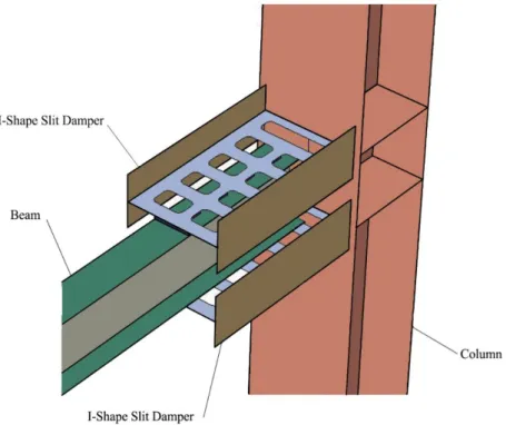
In this research, the proposed connection includes two I-shape slit dampers that connected to the flanges of the beam Figure 1 . Under seismic loading, the slit dampers transfer tension and compression forces of the beam flanges to the column. The couple of forces develop bending moment in the connection. Many slits exist in the web of slit dampers. Stress concentration around the slits causes to yield steel material in the web of slit dampers. Yield-ing of steel material dissipates some of the seismic energy and increases the ductility of connection. Also, the rota-tional capacity of connection is increased because of the yielding materials. The capacity of plastic rotation is an important parameter in the connections. According to FEMA-350 2000a , FEMA355-D 2000b and AISC 358-10 2010 criteria, the rotation capacity must be at least 0.04 radian in special moment frames SMF . Also, the mini-mum resistant moment of this rotation must be at least 0.8Mp, where Mp is the plastic moment of the beam. The plastic moment of the beam Mp obtains from multiplying the yield stress of beam by the plastic modulus of the beam section.
In the proposed connection, welding of the slit dampers to the column and the beam have been designed in the way that slit parts can have displacement parallel to the beam axis. This freedom of displacement yields the slit dampers in the seismic movements and dissipates some of the seismic energy. In order to stress concentration on the dampers, the column, the panel zone and the beam experience less or no damage.
Figure 1: proposed connection with slit dampers.
2 3 3
u
H
í ý
ï ¢ ï
ï ï
î þ 2
In equations 1 and 2 , the first term is related to flexural moment and the second term is related to shear force. Where n number of struts; B struts width; sy yield stress; su ultimate stress; t strut thickness; 𝐻′ equivalent height is indicated in Figure 2 2 2 /
T
H¢ =H + r H ; HT total strut height.
The analytical model of connection is shown in Figure 3. In the idealized model, beam connected to springs top and bottom slit dampers and the springs are connected to the column. Shear force and bending moment of the beam can be calculated in different states.
Figure 2: Geometry of the slit damper.
If Py governs on the slit dampers, shear force of the beam Wy and bending moment of the connection My can be found as follows:
1 2 y y P d W L ⋅ = 3 1 2 y y y
P d L
M W L
L
⋅ ⋅ = ⋅ =
4 Where L is the beam length and L1 is the distance between loading point and middle of the slit dampers.
If Pu governs on the slit dampers, shear force of the beam Wu and bending moment of the connection Mu can be obtained as follows:
1 2 u u P d W L ⋅ = 5 1 2 u u u
P d L
M W L
L
⋅ ⋅ = ⋅ =
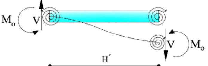
6 In equations 1 to 6 , only in-plane forces on the dampers are considered. However, some out-of-plane forces act on the struts. Shear force is transferred from the beam to the dampers. This force distributed between all struts of upper and lower dampers. Shear stresses which are caused by the beam shear force are small and negligible in the analytical and simplified model, but secondary effects of the shear forces such as bending moments act on the struts. If out-of-plane forces are considered, relations of Py and Pu should be modified, the modified forces are named Pym and Pum respectively. In this case, Py and Pu in equations 3-6 should be replaced with Pym and Pum respectively. If Pym governs on the slit dampers, out-of-plane shear force V in each strut can be calculated as be-low: = y t W V n 7 Where nt is the total number of struts in connection in upper and lower slit dampers . It can be assumed that ends of each strut are supported by a spring as it is shown in Figure 4. In this case, bending moments at two ends of the struts Mo due to out-of-plane shear forces can be calculated as follows:
¢ ⋅ ⋅ ¢ ¢ ⋅ = = = ⋅ 1 . 2 2 y ym o t t
W H P d H
V H M
n n L
8 Also bending moment Mi due to in-plane shear forces can be calculated as follows:
¢ ⋅ = 2 ym i P H M n 9
Figure 4: out-of-plane shear forces and moments in struts.
Figure 5: plastic asymmetrical bending.
¢ ¢
= + = ⋅ +
⋅
2 2 2 2
1 . ( ) ( )
2
ps i o ym
t
H d H
M M M P
n n L
10 In equation 10 , the first term is related to in-plane forces and the second term is related to out-of-plane forces. It could be realized that the magnitude of Mo is so smaller than Mi. According to Figure 5, plastic moment of cross-section Mps could be obtained as below:
s
s ⋅ ⋅ ⋅
= ⋅( )⋅ =
2 2
y
ps y
B t e A
M e
11 Where A is area of one strut cross-section and e is the distance between the centroid of tension part and compression part. It must be mentioned that the area of the tension part AT and compression part AC are equal
AT AC 0.5A . According to equations 10 and 11 , Pym calculated as below:
s ⋅ ⋅ ⋅ æç ¢ ¢ ö÷÷
-ç
= ⋅ç + ÷÷÷
ç ⋅ è ø 1 2 2 1 . ( ) ( ) 2 2 y ym t
B t e H d H
P
n n L
12 In addition, Pum is obtained as follows:
s ⋅ ⋅ ⋅ æç ¢ ¢ ö÷÷
-ç
= ⋅ç + ÷÷÷
ç ⋅ è ø 1 2 2 1 . ( ) ( ) 2 2 u um t
B t e H d H
P
n n L
13 As it was mentioned before, Mo is so smaller than Mi and resultant moment Mps is so close to Mi. The existence of Mo caused the resultant moment Mps skew from Mi axis. The angle between resultant moment Mps direction and Mi direction a can be calculated as below:
a= - = - ⋅
⋅
1 1
1
2 tan ( o) tan ( )
i t
M n d
M n L
4 Specimen and test setup
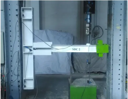
In this research, one 1/2 scale specimen was made to be tested. IPE140 profile was used as the beam. The column was constructed by I-shape plate girder. The thickness of the column web and flanges were 10 mm. This specimen was named SDC2 which both flanges were connected to the column by two slit dampers. Both slit damp-ers had identical section and geometry. IPE200 profile was used to build slit dampdamp-ers. These dampdamp-ers were con-nected to the column by groove welds. The thickness of all stiffener plates was 10 mm. Lateral bracing at the tip of the beam was applied to prevent lateral buckling of the beam. All fillet welds were tested visually. Also, groove welds were checked by the ultrasonic test. Details of the specimen are shown in Figure 6.
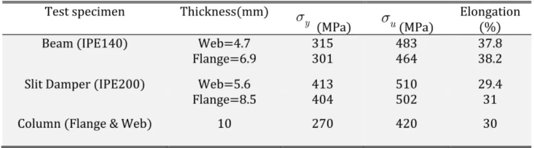
Mechanical properties of the steel materials are presented in Table 1. Holes of dampers were made by the water jet technology, so no extra stresses were extended in the steel materials. The specimen is designed to provide the weak-beam and strong-column theory. In this design, the beam and the slit damper connection have lower mo-ment capacity than the column. The issue guarantees that the column remains in the elastic state. When the slit dampers are used in connections, the capacity of the slit dampers is governed instead of the beam moment capacity. In other words, the slit dampers have lower capacity than the beam and yield before the beam.
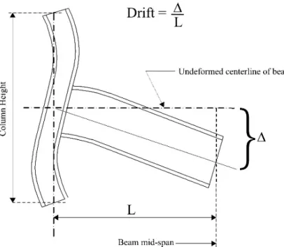
The ends of the column were connected to a rigid frame by hinge supports. The beam was subjected to cyclic loading. The cyclic loading specified in the AISC 341-05 2005 was applied. Applied displacements of the cyclic loading are illustrated in Figure 7. A hydraulic actuator with 200 kN loading capacity and 150 mm stroke was ap-plied to load the specimen. According to FEMA350 and AISC341-05 criteria, rotation of the connection was meas-ured Figure 8 . Displacement of the beam beneath the actuator was measmeas-ured by a laser sensor. The test specimen is shown in Figure 9.
Table 1: Mechanical properties of the steel materials.
Test specimen Thickness mm
y s
MPa su MPa Elongation %
Beam IPE140 Web 4.7 315 483 37.8
Flange 6.9 301 464 38.2
Slit Damper IPE200 Web 5.6 413 510 29.4
Flange 8.5 404 502 31
Figure 6: details of the test specimen.
Figure 8: Angular rotation of connection FEMA 350 .
5 Test observations
Figure 9: Photograph of the test setup.
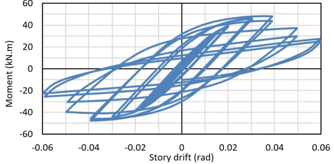
Figure 11: Moment vs. rotation curve of the test specimen.
6 Verification of numerical model
Results of the FE models are not solely adequate to determine structure behavior and are not reliable. The FE models require to compare with experimental data. This approach can determine the accuracy of numerical mod-eling, so experimental and numerical studies on a new type of connection have been done in this research. The numerical model of the specimen was made by ABAQUS software. The FE model was made with the same conditions that the specimen experienced. Results of the numerical model compared with the experimental data.
In ABAQUS software, shell elements were used to simulate beam, column and dampers. For this aim, shell element S4R was applied. S4R is a shell element which has 4 nodes and each node has 6 degrees of freedom and reduced integration was applied for its formulation. Tensile test of steel materials was done on different parts of beam, column and slit dampers. Mechanical properties of the steel materials were obtained from stress-strain curves. Based on the outcome of the coupon tensile test, a true stress-strain curve with reduced strength at large strain after ultimate strain was defined. The strength of steel materials which experience strains greater than the ultimate strain is reduced to simulate the materials behavior. In the numerical simulation, cracks on the dampers were not modeled. This method was used by many researchers such as Pachoumis et al. 2010 and Faridmehr et al. 2015 . They modeled connections and materials behavior for large strains. This technique could simulate the moment reduction in the last cycles. Stress-strain curve of IPE200 web damper according to standard tension test ASTM E8/E8M-16a is shown in Figure 12. Young's modulus and Poisson's ratio of all steel materials were as-sumed 205 GPa and 0.3, respectively.
Lateral bracing at the tip of the beam was modeled similar to specimen conditions. Cyclic displacement on the beam was applied such as loading protocol. Von Mises contours at the end of 0.04 story drift are presented in Figure 13. The Von Mises criterion indicates the yielding state in complex stress combinations. Stress concentrations of FE model exactly occurred on damaged and cracked regions of the slit dampers. The experimental and the FE model cyclic curves are shown in Figure 14. Skeleton curves describe the hysteretic behavior and the ductility of structures which subjected to cyclic loading. In hysteresis loops, a skeleton curve can be drawn by connecting the maximum moment in each cycle. Skeleton curves obtain from experimental data and FE analysis are compared in Figure 15. A good agreement between the experimental and numerical results is observed in Figures 14, 15 .
Figure 12: Stress-strain curve of the slit damper web standard tension test .
Figure 13: Von Mises stress contour of the model SDC2.
Figure 15: Comparing the experimental and the FE skeleton curves.
Table 2: Analytical results of specimen SDC2.
Approach Shear load
Yield state kN Moment Yield state kN.m Maximum load Ultimate state kN Maximum moment Ultimate state kN.m First approach
only in-plane forces
considered 38.46 41.73 47.49 51.53
Second approach in-plane and out-of-plane forces
consid-ered
38.33 41.59 47.33 51.36
Table 3: Experimental, FEM and analytical outcome.
Method Shear load
Yield state kN Moment Yield state kN.m Maximum load Ultimate state kN Maximum moment Ultimate state kN.m
Experimental 35.96 39.02 44.39 48.16
FEM 36.72 39.84 46.86 50.84
Analytical 38.33 41.59 47.33 51.36
The maximum shear force of beam in the ultimate state is equal to 44.39 kN Table 3 . The specimen SDC2 has upper and lower dampers and these dampers have 20 struts. Therefore, the out-of-plane shear force of each strut is about 2.2 kN. This force caused a shear stress about 13 MPa. This shear stress is small and could be neglected in the simplified model.
7 Numerical study
Figure 16: Geometry of the numerical models.
Table 4: Specifications of numerical models.
Model Beam Column Top Slit
Damper Bottom Slit Damper
C2-18 IPE180 IPB300 S24-1 S24-1
C2-22 IPE220 IPB300 S24-2 S24-2
C1-18 IPE180 IPB300 S24-1
-C1-22 IPE220 IPB300 S24-2
-Figure 17: Geometry of the slit dampers were used for numerical models.
8 Results of the FE models
Skeleton curves of moment vs. rotation are presented in Figure 20. Based on the skeleton graphs, bending moments in full plastic state My and moments in the ultimate state Mu can be calculated. Also, these moments can be obtained analytically using Equations 1-6 . Table 5 shows FEM and analytical moment values of different models.
A difference between models with two dampers and models with just one damper is related to rigidity. Rota-tional rigidity is equal to the slop of moment vs. rotation graph for every single cycle. The rigidity of the models under cyclic loading gradually decreases due to the formation of plastic hinges in the dampers.
Structures under the effects of reversible cyclic loads dissipate some of the energy as plastic deformations. Value of energy dissipation is important for ductile structures especially in the case of seismic loads. Energy is equal to force which is multiplied by its movement. Therefore, dissipated energy is equal to the area under the load vs. displacement graphs in hysteresis diagrams. Dissipated energy graphs of all numerical models are shown in Figure 21. The models which dissipate more energy at the end of the loading process, have more efficiency in reversible cyclic loads such as an earthquake. This parameter expressed ductility of the structure. Two important parameters of each model, the moment at 0.04 story drift and total dissipated energy, are expressed in Table 6.
Figure 19: Von Mises stress contours of the FE models.
Figure 20: Skeleton curves of the numerical models.
Table 5: Comparison between analytical and FEM solutions.
Model Maximum analytical
moment kN.m Maximum numeri-cal moment kN.m
Analytical/ FEM
C2-18 81.07 98.26 0.83
C2-22 107.6 125.4 0.86
C1-18 81.07 99.2 0.82
C1-22 107.6 124.8 0.86
Table 6: Moment capacity and total dissipated energy.
Model
P
M M
at 0.04 drift
Total dissipated en-ergy kJ
C2-18 1.87 35.87
C2-22 1.26 52.44
C1-18 1.95 36.79
C1-22 1.04 39.91
9 Conclusions
In this paper, a new structural connection was proposed. It uses I-shape slit dampers to increase deformation capacity and ductility of the structure during an earthquake. In the proposed beam to column connection, two slit dampers connect the top and bottom flanges of the beam to the column. The experimental specimen was made with two dampers. A quasi-static cyclic loading was conducted on the half-scale specimen. Also, some numerical models were made with two dampers and other FE models had just one damper. The results are noticed as below.
- According to the experimental and numerical results, the connection exhibits a stable hysterical behavior under cyclic loading and large story drifts.
- Using two slit dampers in the connections increases the ductility and rotational capacity rather than using one damper.
- Based on the experimental results, energy absorption in the slit dampers prevents the damages of beam, column and welds. Energy is dissipated by plastic deformations and cracks in the slit dampers. The numerical results show that Von Mises stresses are concentrated on the ends of each strut. Also, these regions were cracked in the experimental specimen.
- Theoretical solutions of the yield and ultimate state and the numerical results are in good agreement with the experimental data.
- All experimental and numerical results present resistant moment more than 0.8Mp at 0.04 story drift. This subject proves the great moment capacity of the proposed connection.
Further researches and more experimental studies are needed to identify the connection behaviors. Effect of different sizes of the beams, columns and slit dampers should be investigated.
References
AISC 341-05. 2005 . Seismic provisions for structural steel buildings. Published by the American Institute of Steel Construction, USA.
AISC 358-10. 2010 . prequalified connections for special and intermediate steel moment frames for seismic appli-cations. Published by the American Institute of Steel Construction, USA.
ASTM E8/E8M-16a 2016 . Standard test methods for tension testing of metallic materials. Published by the Amer-ican Society for Testing Materials, USA.
Banisheikholeslami, A., Behnamfar, F., & Ghandil, M. 2016 . A beam-to-column connection with visco-elastic and hysteretic dampers for seismic damage control. Journal of Constructional Steel Research, 117: 185-195.
Brown, E. H. 1967 . Plastic asymmetrical bending of beams. International Journal of Mechanical Sciences, 9 2 : 77-82.
Chan, R. W., & Albermani, F. 2008 . Experimental study of steel slit damper for passive energy dissipation. Engi-neering Structures, 30 4 : 1058-1066.
Faridmehr, I., Osman, M. H., Tahir, M. M., Nejad, A. F., & Hodjati, R. 2015 . Severe Loading Assessment of Modern and New Proposed Beam to Column Connections. Latin American Journal of Solids and Structures, 12 7 : 1202-1223.
FEMA 350. 2000a . Recommended seismic design criteria for new steel moment-frame buildings-FEMA 350. Fed-eral Emergency Management Agency FEMA , USA.
FEMA-355D. 2000b . State of the art report on connection performance. Report No. FEMA-355D. Federal Emer-gency Management AEmer-gency FEMA , USA.
Hedayat, A. A., Saffari, H., & Mousavi, M. 2013 . Behavior of steel reduced beam web RBW connections with arch-shape cut. Advances in Structural Engineering, 16 10 : 1645-1662.
Johnson, W., and Mellor, P. B. 1983 . Engineering plasticity. Horwood.
Karamodin, A., & Zanganeh, A. 2017 . Seismic Design and Performance of Dual Moment and Eccentrically Braced Frame System Using PBPD Method. Latin American Journal of Solids and Structures, 14 3 : 441-463.
Maleki, S., & Mahjoubi, S. 2013 . Dual-pipe damper. Journal of Constructional Steel Research, 85: 81-91.
Mirghaderi, S. R., Torabian, S., & Imanpour, A. 2010 . Seismic performance of the Accordion-Web RBS connection. Journal of Constructional Steel Research, 66 2 : 277-288.
Oh, S.-H., Kim, Y.-J., & Ryu, H.-S. 2009 . Seismic performance of steel structures with slit dampers. Engineering Structures, 31 9 : 1997-2008.
Pachoumis, D. T., Galoussis, E. G., Kalfas, C. N., & Efthimiou, I. Z. 2010 . Cyclic performance of steel moment-resisting connections with reduced beam sections—experimental analysis and finite element model simulation. Engineering Structures, 32 9 : 2683-2692.
Popov, E. P., and K. C. Tsai. 1989 . Performance of large seismic steel moment connections under cyclic loads. En-gineering Journal, 26: 51-60.
Saffari, H., Hedayat, A., & Nejad, M. P. 2013 . Post-Northridge connections with slit dampers to enhance strength and ductility. Journal of Constructional Steel Research, 80: 138-152.
Skinner, R., Kelly, J., & Heine, A. 1974 . Hysteretic dampers for earthquake-resistant structures. Earthquake Engi-neering & Structural Dynamics, 3 3 : 287-296.