Ultimate strength formulations for FPSO stiffened panels under
com-bined compression and shear with initial imperfections and damage
Abstract
Accidental collision of striking objects, such as a supply vessel, into the side panel of a FPSO highly influences its ultimate strength assessment. An em-pirical formula for predicting the ultimate strength of damaged stiffened panels under combined loading of shear and longitudinal compression is empirically derived in this work based on curve fitting of quasi-static non-linear finite element FE analyses. Initial imperfections are introduced by scaling the first buckling mode shape and the damage is caused by residual deformation from a rigid sphere indentation. A pure shear loading is ap-plied at several levels followed by compression loading using the modified Riks method for a number of sphere indentation damages. The suggested formula for a typical FPSO stiffened side shell panel presented an excellent correlation with the nonlinear FE results and can be particularly useful in the preliminary design phase no damage and for a quick estimation of the panel residual strength with indentation damage.
Keywords
ultimate strength, FPSO, edge shear, longitudinal compression, damage
1 INTRODUCTION
Floating, production, storage and offloading units FPSOs are employed to receive oil and gas through the riser system, process it and store on board the vessel tanks, remaining on position by means of a mooring system or dynamic positioning system as described by Moan et al. 2003 . According to HSE 2000 report, during opera-tion they can be struck by: a supply vessels in service to and from the installaopera-tion, b tankers loading at the field, c ships and fishing vessels passing the installation and d floating installations such as flotels, for example. Part of such a collision energy may be dissipated as strain energy in the FPSO and in the striking vessel itself, possibly leading to a considerable amount of plastic strain. Due to lack of information about the ultimate strength assess-ment of the impacted zone, classification societies generally require to fix it immediately after damage. As an off-shore repair can be cumbersome and costly, an accurate residual strength assessment is very important to help determining what kind of action is the most appropriate.
Ship and offshore structures consist of continuous panels stiffened by stiffeners and support members. As pointed out by Hughes and Paik 2010 , the panels of ships may be subjected to a number of operational loading components static and wave-induced acting on the structure, such as: biaxial tension/compression, edge shear and in-plane bending, which are mainly induced by overall hull girder bending and torsion. Lateral pressure load-ing arises from water pressure and cargo weight. Although the extreme value of each component may not occur simultaneously, they interact with each other, affecting the ultimate strength interaction response.
Ship hull plates and stiffened panels mechanical response have been studied for decades. As highlighted by the ISSC Committee ISSC, 2009 , it is not possible to determine the true margin of structural safety under ex-treme loads if the ultimate strength remains unknown. As a large degree of geometric nonlinearity and material nonlinearity occurs before and after the ultimate strength capacity has been reached, non-linear elastoplastic FE analyses is one of the preferred methods for limit state based assessment. The main influential factors for such calculations are related to: a geometrical factors; b material parameters associated to plasticity, including strain hardening, and fracture; c initial imperfections due to fabrication and welding; d residual stresses caused by damage; e temperature factors and f strain rate dependent response.
The ultimate strength response of panels under pure shear loading received some research attention in the last years. Alinia 2005 performed a study into optimization of stiffeners in plates subjected to shear loading
Nicolau Antonio dos Santos Rizzoa Marcelo Caireb*
a PETROBRAS, Engenharia, Rio de Janeiro, RJ,
Brasil. E-mail: [email protected]
b Núcleo de Estruturas Oceânicas NEO , Programa
de Engenharia Naval e Oceânica, Departamento de Engenharia Naval e Oceânica, Universidade Fede-ral do Rio de Janeiro- UFRJ, Rio de Janeiro, RJ, Brasil. E-mail: [email protected]
*Corresponding author
http://dx.doi.org/10.1590/1679-78254320
using FE analysis followed by Alinia and Dastfan 2006 who studied the effect of surrounding members i.e. beams and columns on the overall behavior of thin steel plate shear walls. They conclude that the flexural stiff-ness of surrounding members has no significant effects, either on elastic shear buckling or on the post-buckling behaviour. The torsional rigidity has a significant effect only on the elastic buckling load, and the extensional stiff-ness slightly affects the post-buckling capacity. In a further study, Gheitasi and Alinia 2010 investigated the slenderness classification of unstiffened metal plates under shear loading dividing it into slender, moderate and stocky categories. Zhang et al. 2008 developed a simple formula for the ultimate shear strength of plates and verified against Abaqus 2014 FE results and a large number of published results. They also assessed the suita-bility of the formula application for a stiffened panel structure representing the side shell of an oil tanker. From the good correlation obtained they concluded that the ultimate shear strength of the stiffened panel could be de-termined analyzing a single plate of the same thickness with simply supported boundaries and edges constrained to remain straight. Rizzo et al. 2014 performed a parametric FE analysis, with a similar stiffened panel as the previous mentioned work, and observed that as the thickness value increases, the ultimate strength of the stiff-ened panel tends to be in closer agreement with the plate. They have also observed that, as expected, higher val-ues of initial imperfection amplitudes based on the first buckling mode leads to lower limit state valval-ues.
The ultimate shear strength reduction characteristics of steel plates due to local denting damage have been investigated by Paik 2005 . The damage has been modeled as initial geometric deformation without taking into account the residual stresses or strains. He observed that as the dent diameter increases the plate ultimate shear strength decreases significantly and that the worst situation occurs when the dent is located at the plate center.
Paik et al. 2003 employed nonlinear FE analyses to investigate the ultimate strength of dented steel plates under axial compressive loads. As in his work for shear loading, the damage was considered as an initial stress free deformation in the mesh. They observed that as the dent location is closer to the unloaded plate edge the ultimate strength decreases compared to the central position. Raviprakash et al. 2012 studied the influence of various dent parameters dent length, dent width, dent depth and angle of orientation of the dent on the static ultimate strength of thin square plates of different thicknesses under uniaxial compressive loading.
For stiffened panels under compressive loading with damage, Xu and Soares 2013 has recently performed quasi-static nonlinear FE analysis including the residual stress and the dent deflections caused by indentation. From the case study performed it has been observed that the residual stress caused by the indentation slightly affects the ultimate strength of the dented stiffened panels considered.
In terms of ultimate strength formulations, Paik et al. 2001 developed relations of long and/or wide steel plate elements subject to a combination of four load components, namely longitudinal compression/tension, transverse compression/tension, edge shear, and lateral pressure loads. The plate element is assumed to be simp-ly supported along all four edges kept straight.
From the literature review performed, one can observe that none of the previous researchers considered the combined action of shear and compression in a limit state assessment of a stiffened panel structure with residual plastic strain caused by indentation.
In the present work, a quasi-static nonlinear FE model is developed in Abaqus 2014 for a typical FPSO stiff-ened side panel subjected to combined loading of edge shear and longitudinal compression as detailed in Section 2. Initial imperfections are included scaling the first buckling mode shape amplitude followed by damage intro-duction with the indentation of a rigid sphere in the central part of the stiffened panel. In the next analysis step the indenter is removed, allowing the model to simulate the panel springback effect. The residual stress is then considered in the ultimate strength assessment using the Riks method for a variety of indenter displacements. Such nonlinear FE analysis are quite time consuming for preliminary design phases and, consequently, robust semi-empirical methods are preferred in that stage. In that sense, formulations are proposed in Section 3 with and without indentation damage and the coefficients adjusted using the FE model results. A very good correla-tion is observed for the case study presented where one can observe that the ultimate strength is more sensitive to compression than to shear and that higher levels of damage lead to lower values of limit state strength, as ex-pected.
2 NONLINEAR FINITE ELEMENT MODEL OF FPSO STIFFENED PANELS
ultimate strength assessment under combined longitudinal compression and edge shear loading. The model ge-ometry and material parameters are presented in Section 2.1 while the prescribed boundary conditions are de-scribed in Section 2.2. Each of the following analyses steps are presented in Section 2.3: i buckling analysis for initial imperfection estimation based on the first response mode, ii quasi-static analysis of the rigid body inden-tation to simulate the damage and the spring back response, iii quasi-static analyses subjected to shear loading taking into account the initial imperfections and the residual stresses from indentation followed by iv the modi-fied Riks method Crisfield 1981 analyses applying compression to estimate the ultimate strength under com-bined loading. For the case with no indentation damage i.e. only initial imperfections step ii is disregarded. 2.1 Model definition
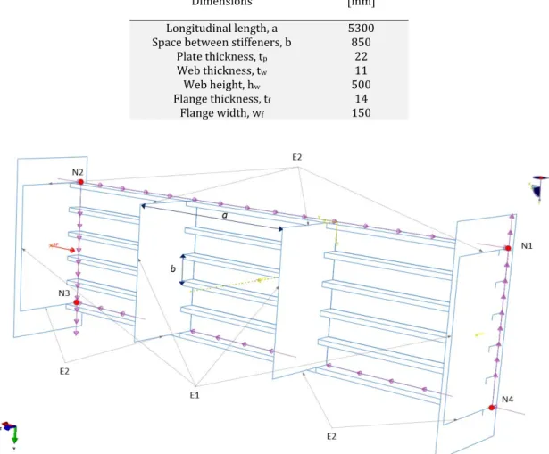
A number of model types can be employed for the ultimate strength assessment of a ship hull, including: a the entire hull model, b one to three cargo hold models and c stiffened panels including different number of longitudinal stiffeners and web frames and even d a single panel itself ISSC, 2009 . The complexity in defining correct boundary conditions increases as the model goes from a to d , especially if residual stress is present. In general, if there is uncertainty about the correct boundary conditions, it is probably better to include that portion in the structural model, even if more computational resources are required. A stiffened panel with six 6 stiffen-ers of length a and distance b from each other extended in the longitudinal with an additional web frame to each
side, as shown in Fig. 1 has been selected for the present case study, corroborated by the verification of zero equivalent plastic strain in the model boundaries after collision. The main dimensions are presented in Table 1.
Table 1: Panel dimensions.
Dimensions mm
Longitudinal length, a 5300
Space between stiffeners, b 850
Plate thickness, tp 22
Web thickness, tw 11
Web height, hw 500
Flange thickness, tf 14
Flange width, wf 150
The outermost contact point of the rigid sphere is located in the center of the panel, both in longitudinal and transversal directions. A spherical rigid surface with diameter Db = 1000mm is employed to cause the
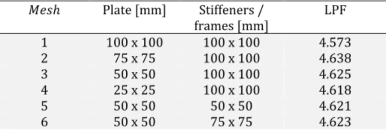
indenta-tion damage. For the contact formulaindenta-tion, the hard contact pressure-overclosure relaindenta-tion is used with no fricindenta-tion between the surfaces. The three dimensional 4-node S4R quadrilateral shell element is employed for the mesh. The following discretization scheme is selected after a mesh sensitivity study considering the ultimate strength under pure compression, as presented in Table 2: a Plate - 50 x 50 mm and b Longitudinal stiffeners and frames - 100 x 100 mm.
Table 2: Mesh sensitivity study under pure compression – Load proportionality factor LPF
𝑀𝑒𝑠ℎ Plate mm Stiffeners /
frames mm LPF
1 100 x 100 100 x 100 4.573
2 75 x 75 100 x 100 4.638
3 50 x 50 100 x 100 4.625
4 25 x 25 100 x 100 4.618
5 50 x 50 50 x 50 4.621
6 50 x 50 75 x 75 4.623
The effect of strain hardening on the elastoplastic behavior of a stress-free dented steel plate under edge shear loads has been investigated by Paik 2005 , who observed larger ultimate shear strength values when hardening was considered, but adopted the more conservative elastic and perfectly plastic material model for the proposed empirical formulation assessment. For the present case, i.e., a panel subjected to longitudinal compres-sion and edge shear loading, plastic hardening gives an increase in the ultimate strength because the loss of stabil-ity is followed by the appearance of plastic strains and, consequently, material hardening. In that sense, for formu-lation simplification purposes and to be on the conservative side, an elastic perfectly plastic material model with no hardening is employed to the steel material. Therefore, all the material parameters required are given by the following properties: i elastic modulus, E =210GPa ii Poisson ratio n =0.3 and iii yield strength:
355
Y MPa
s = tY =sY / 3=204.96MPa .
2.2 Boundary conditions
The X axis is taken in the direction parallel to the FPSO length and the Y axis is pointing upwards toward
the deck. Boundary condition are used to eliminate the rigid body motion, therefore the corner nodes N1, N2, N3 and N4 have the translation fixed in Z -direction. In addition, the corner node N1 is also fixed in the translational X and Y directions and the opposite corner node N3 is fixed in the translation Y direction. The Z direction
web frame edges E2 boundary conditions are fixed in Z translation and Y rotational degrees of freedom. For
the Y direction web frame edge E1 , the rotation degrees of freedom are fixed in X and Z directions.
2.3 Analysis steps Initial imperfections:
Figure 2: First buckling mode shape.
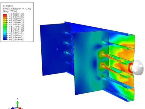
Collision damage and springback response: The second analyses step consists in a rigid sphere indentation in the middle of the model. The quasi-static analyses methodology disregards the dynamic effects and its influence in the response. For the parametric variation, four displacements D are applied: 50, 100, 200 and 300 mm. Fig-ure 3 shows the stress distribution for the case with a 200 mm sphere indentation and an initial imperfection amplitude of d = 5m m . Once the rigid sphere is removed, the stiffened panel will spring back, recovering the
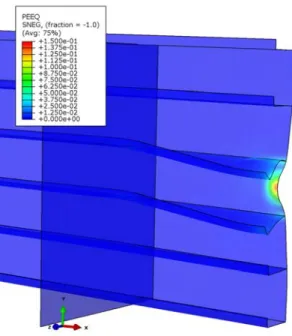
elastic deformation. The non-recoverable plastic deformation causes a residual stress distribution which remains in the further steps and the permanent plastic strain as shown, respectively, in Figures 4 and 5.
Figure 4: Residual stress distribution after indentation sbringback – 200 mm displacement.
Figure 5: Equivalent plastic strain after indentation – 200 mm displacement Scale factor 2
Shear loading: Edge shear is the first loading to be applied after damage caused by sphere indentation. In or-der to further apply the longitudinal compression for a given applied edge shear, two rigid surfaces are modeled and placed in the model endings. For one, all the degrees of freedom are restrained and for the other, only the X
translation is free while the plate itself is free to rotate about Z axis. Due to the frictionless contact formulation
adopted, the model endings are allowed to tangentially slide without separation between the surfaces. Figure 6 illustrates the final configuration of the plate after an edge shear loading of 3000N /mm. The visualization is
Figure 6: Shear loading step D = 200m m , d = 5m m , Scale factor 25 .
Ultimate strength: Longitudinal compression is the final loading to be applied in the rigid surfaces for several levels of pre-applied edge shear loading. The ultimate strength capacity is obtained by applying the loading be-yond the limit point, i.e., where the load-displacement response shows a negative stiffness and the structure re-leases strain energy to remain in equilibrium. The modified Riks method described by Crisfield 1981 and im-plemented in Abaqus 2014 using Newton’s method to solve the nonlinear equilibrium equations is an algorithm that allows effective solution of such cases and is consequently employed here. As described in Abaqus manual, the loading during a Riks step is always proportional, being the current load magnitude described by:
0 ( 0)
total ref
P =P +l P -P , where P0 are any loads that exist at the beginning of the step edge shear in the present
case , Pref is the reference load longitudinal compression and l is the load proportionality factor LPF . This approach provides solutions regardless of whether the response is stable or unstable. For illustration purposes, Figure 7 shows the load proportionality factor versus “arc-length” for two indenters displacements D =50 and
200mm for an edge shear loading of 3000N /mm. The ultimate limit strength is calculated when the derivative of
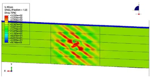
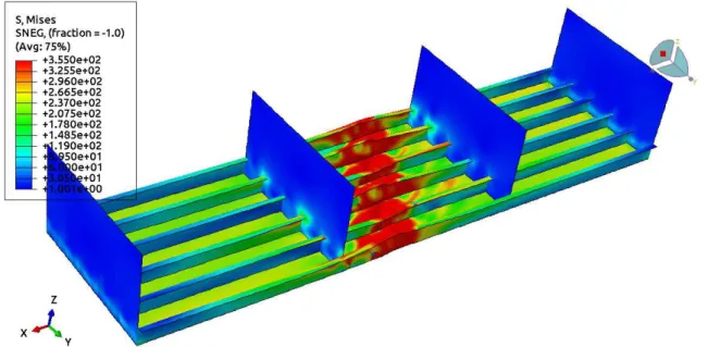
the curve is equal to zero. Figure 8 illustrates the configuration of the von Mises stress distribution beyond the limit point arc-length value of approximately 2.85 under the combined edge shear and longitudinal compres-sion loading taking into account the initial imperfection and damage. The interaction relation curve s s/ yvs
/ y
t t for different values of initial imperfection amplitude d without plastic damage from indentation is pre-sented in Figure 9. In Section 3.2, the same relation is prepre-sented for a number of indentation displacements, keep-ing a constant initial imperfection given by d = 5m m . The results discussion is presented in the next section
to-gether with the proposed ultimate strength formulation.
Figure 8: Ultimate strength under combined loading Scale factor 2 .
3 ULTIMATE STRENGTH FORMULATIONS
Two formulations are presented, one in Section 3.1 to evaluate the effect of different initial imperfections amplitudes based on the first buckling mode without damage from indentation and another in Section 3.2 to evaluate the indenter damage effect considering a fixed value of initial imperfection amplitude.
3.1 Without damage D =0
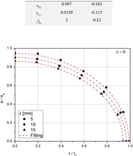
Figure 9 illustrates the ultimate strength interaction relation for stiffened panel under combined edge shear and longitudinal compression for different imperfection amplitudes d and without indentation damage. As ex-pected, the higher the initial imperfection the lower the ultimate strength, following a proportional relation for the three cases analyzed. It can also be observed that the curves for each imperfection amplitude follows a typical ellipsoid shape and consequently the following relation is proposed,
/ / 1 y y a b d d a b d d
s s t t
æ ö÷ æ ö÷
ç ÷ ç ÷
ç ÷ +ç ÷ =
ç ÷ ç ÷
ç ÷ ç ÷
ç ç
è ø è ø 1
where ad, bd and bd are coefficient functions dependent on the initial imperfection amplitude d according to the
following,
0 1
=
p
a a a
t
d d d d
æ ö÷
ç ÷
ç + çççè ø÷÷÷
2a
0 1
=
p
b b b
t
d d d d
æ ö÷
ç ÷
ç + çççè ø÷÷÷
2b
0 1
=
p t
d d d d
b b +b æçççç ö÷÷÷÷÷
çè ø 2c
and ad is constant and equal to 2. The coefficients are adjusted employing the nonlinear least square method
Table 3: Coefficients – initial imperfection amplitude
𝑖 0 1
i
ad 0.987 -0.181
i
bd 0.0158 -0.113
i
d
b 2 -0.22
Figure 9: Interaction relation and formulation fitting for longitudinally stiffened panel under combined longitudinal compression and edge shear loading for different initial imperfection amplitudes.
3.2 With damage D > 0
According to the DNV-OS-C401 Det Norske Veritas, 2010 rule, the maximum out of plane displacement for plates initial imperfection amplitude is 0.5% of the distance between stiffeners. Consequently, in all the subse-quent results presented, the imperfection amplitude was fixed and given by d = 5m m .
The total energy absorbed by a FPSO in a collision situation is an important parameter to be observed. De-pending on its magnitude, it can be close to the structure accidental limit strength energy as defined in the stand-ard NORSOK N-003 NORSOK Standstand-ard, 2007 . The collision energy can be estimated on the basis of the relevant masses, velocities and striking ship directions where the velocity can be determined based on the assumption of a drifting ship, or on the assumption of erroneous operation. Assuming the FPSO as a fixed installation and the striking ship as a rigid indenter, the collision energy to be dissipated as total strain energy E may be
approxi-mately described by,
2 1
( )
2 s s s
E = m +a v
3 where ms is the ship mass, as the ship added mass and vs the impact speed.
Figure 10 shows the total strain energy E resulting from the FE simulations normalized with the accidental
limit strength energy EALS versus the residual displacement DR normalized with the bulb diameter
1000 B
D = mm. EA LS is calculated based on NORSOK N-003 2007 recommendations for frontal collisions in
hydrodynam-ic added mass of 10% for bow and stern impact, leads to a value of EALS =11MJ. The plot suggests a quadratic
fitting that can be obtained with the following relation,
2
1 2
R R
ALS b b
E
B B
E D D
æ ö D çD ÷÷ = + çç ÷÷
çè ø 4
Figure 10: Normalized energy as a function of normalized residual displacement EALS =11MJ , DB =1000mm .
The adjusted coefficients B1 and B2 are also shown in Figure 10. Table 4 presents the normalized total strain
energy and normalized residual displacement after indentation for the different values of D analyzed. It can be observed that the total strain energy considering a sphere indentation of D = 300m m leads to only
approxi-mately 8% of the NORSOK standard accidental limit strength energy. It should also be noted that DR is a quantity
that can be estimated in the field and used as basis for an estimation of the collision energy and comparison to the accidental limit strength energy provided by the standard.
Table 4: Residual displacement and energy for each bulb displacement
[m m]
D DR / Db E /EALS%
50 0.028 0.20
100 0.069 0.88
200 0.165 3.80
300 0.253 8.05
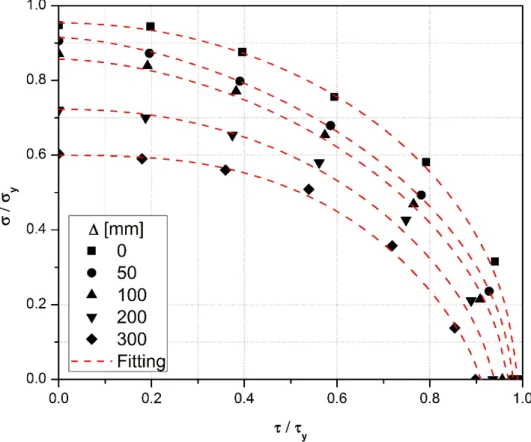
loading with residual plastic strain damage. Figure 11 shows the ultimate strength interaction relation s s/ y vs / y
t t for the FPSO stiffened panel under combined longitudinal compression and edge shear loading for the different sphere indentations applied. It can be observed, as expected, that higher levels of indentation leads to lower ultimate strength and that the influence is higher for higher values of s t/ .
Figure 11: Interaction relation and formulation fitting for longitudinally stiffened panel under combined longitudinal compression and shear loading for different damages - DB =1000mm, d = 5m m
Based on a similar observation for the interaction relation without damage previously presented, where the non-dimensional curves follow a shape similar to an ellipse for the different levels of damage rigid sphere inden-tation the following relation is proposed,
/ /
1
y y
a b
a b
s s D t t D
D D
æ ö÷ æ ö÷
ç ÷ ç ÷
ç ÷ +ç ÷ =
ç ÷ ç ÷
ç ÷ ç ÷
ç ç
è ø è ø 5
where now, the coefficients aD, bD, aD and bD are functions dependent on the residual displacement DR with a
fixed sphere diameter Db and given by,
0 1
= R
b
a a a
D
D D D
æD ÷ö ç ÷ + çç ÷÷
çè ø 6a
0 1 R
b
b b b
D
D D D
æD ÷ö ç ÷ = + çç ÷÷
0 1 R
b
D
aD aD aD
æD ÷ö ç ÷ = + çç ÷÷
çè ø 6c
2
0 1 2
= R R
b b
D D
bD bD bD bD
æD ö÷ æD ö÷
ç ÷ ç ÷
+ çç ÷÷+ çç ÷÷
ç ç
è ø è ø 6d
Based on the FE results, Eq. 5 is adjusted based on the nonlinear least square method and the resulting co-efficients presented in Table 5. Figure 11 shows the comparison between the semi-empirical model fitting and the FE results, where an excellent correlation can also be observed.
Table 5: Coefficients – damage condition
i 0 1 2
i
aD 0.954 -1.40 -
i
bD 0.984 -0.30 -
i
aD 1.981 -2.67 -
i
bD 1.529 2.35 10.5
4 SUMMARY AND CONCLUSIONS
A nonlinear FE model for a typical FPSO side shell stiffened panel, subjected to combined edge shear and lon-gitudinal compression loading is presented and a parametric study performed to investigate the initial imperfec-tion and damage influences on the panel ultimate strength. Initial imperfecimperfec-tions are introduced by scaling the first buckling mode shape and the damage is caused by residual plastic deformation from a rigid sphere indentation.
A pure shear loading is applied at several levels followed by compression loading using the modified Riks method for a number of sphere indentation damages. The main observations from the nonlinear FE analyses car-ried out can be summarized as follows:
i. higher values of initial imperfections and damage lead to lower ultimate strength, as expected.
ii. the ultimate strength with damage under combined loading is more sensitive to compression than to shear, as it has been observed that damage influence increases as the relation s t/ increases.
Based on the parametric analyses, it has been observed that the non-dimensional interaction relation curves
/ Y
s s vs t / tY present a form similar to an ellipsoid. A semi-empirical formulation has been suggested with
parameters dependent on the initial imperfection amplitude when no damage is considered . Another formula-tion has been proposed with parameters dependent on the residual displacement for a specific value of sphere radius and initial imperfection amplitude. Both presented an excellent fitting of the nonlinear FE results and can be particularly useful in the preliminary design phase no damage and for a quick estimation of the panel residu-al strength with damage.
To extend its offshore field applicability, further analyses are required to generalize the formulation as func-tion of both the residual displacement, sphere radius and relative posifunc-tion of the contact point in the stiffened panel parameters combination.
ACKNOWLEDGMENTS
The authors acknowledge the support of ANP-PRH 03 and PETROBRAS for the present work.
References
Moan, T., Amdahl, J., Wang, X.Z. and Spencer, J., 2003 . “Risk Assessment of FPSOs with Emphasis on Collision,” SNAME Transactions, 110:307-339.
International Ship and Offshore Structure Congress ISSC . 2009 . “Ultimate strength. Report of Technical Com-mittee III.1”, International Ship and Offshore Structures Congress, Seoul, Korea, August.
Hughes, O. F., Paik, J.K., 2010 . “Ship structural analysis and design”. The Society of Naval Architects and Marine Engineers New Jersey .
Alinia, M. 2005 . “A study into optimization of stiffeners in plates subjected to shear loading.” Thin-Walled Struc-tures, 43 5 :845 – 860.
Alinia, M. and Dastfan, M. 2006 . “Behaviour of thin steel plate shear walls regarding frame members.” Journal of Constructional Steel Research, 62 7 :730 – 738.
Gheitasi, A. and Alinia, M. 2010 . “Slenderness classification of unstiffened metal plates under shear loading.” Thin-Walled Structures, 48 7 :508 – 518.
Zhang, S., Kumar, P., and Rutherford, S. E. 2008 . “Ultimate shear strength of plates and stiffened panels.” Ships and Offshore Structures, 3 2 :105–112.
ABAQUS, 2014 , “ABAQUS Documentation”. Dassault Systèmes, Providence, RI, USA.
Rizzo, N.A.S, Amante D.A., Estefen S.F., 2014 . “Ultimate shear strength of stiffened panels for offshore struc-tures.” OMAE2014-23155, 33rd International Conference on Ocean, Offshore and Arctic Engineering; vol. 4A: Structures, Safety and Reliability. San Francisco, California, USA.
Paik, J. K. 2005 . “Ultimate strength of dented steel plates under edge shear loads.” Thin-Walled Structures, 43 9 :1475 – 1492.
Paik, J. K., Lee, J. M., Lee, D. H. 2003 . “Ultimate strength of dented steel plates under axial compressive loads.” International Journal of Mechanical Sciences, 45:433-448.
Raviprakash, A., Prabu, B., and Alagumurthi, N. 2012 . “Residual ultimate compressive strength of dented square plates.” Thin-Walled Structures, 58:32 – 39.
Xu, M. C. and Soares, C. G. 2013 . “Assessment of residual ultimate strength for wide dented stiffened panels sub-jected to compressive loads.” Engineering Structures, 49:316 – 328.
Paik, J. K., Thayamballi, A. K., and Kim, B. J. 2001 . “Advanced Ultimate Strength Formulations for Ship Plating Under Combined Biaxial Compression/Tension, Edge Shear, and Lateral Pressure Loads.” Marine Technology, 38 1 :9-25.
Crisfield, M.A., 1981 . “A fast incremental/iterative solution procedure that handles snap-through” Computer & Structures, 13:55 – 62.
Det Norske Veritas, 2010 , “DNV-OS-C401 - Fabrication and Testing of Offshore Structures”