Jaime Moreira Machado Faria
Licenciatura em Engenharia de Micro e Nanotecnologias
Production and optimization of hybrid fibrillary
gels by colloidal electrospinning
Dissertação para Obtenção do Grau de Mestre em Engenharia de Micro e Nanotecnologias
Orientador: Doutora Coro Echeverria Zabala, Investigadora em Pós-doutoramento, CENIMAT-I3N Departamento de Ciência dos Materiais, Faculdade de Ciências e Tecnologia da Universidade Nova de Lisboa
Co-orientador: Doutora Paula Isabel Pereira Soares, Investigadora em Pós-doutoramento, CENIMAT-I3N Departamento de Ciência dos Materiais, Faculdade de Ciências e Tecnologia da Universidade Nova de Lisboa
Júri
Presidente: Doutor Rodrigo Ferrão Paiva Martins, Professor Catedrático, FCT-UNL Arguente: Doutor Jorge Alexandre Monteiro Carvalho Silva, Professor Auxiliar, FCT-UNL
Vogal: Doutora Coro Echeverria Zabala, Investigadora em Pós-doutoramento, FCT-UNL
iii
Production and optimization of hybrid fibrillary gels by colloidal electrospinning
Copyright © Jaime Moreira Machado Faria, 2016
v
vii
“Break the cycle. Rise above. Focus on science”
ix
Acknowledgments/Agradecimentos
Agradeço à minha orientadora, Doutora Coro Echeverria Zabala, não só pela ajuda prestada na parte experimental, mas também pelas muitas correções na parte escrita. Obrigado por me teres mostrado que é preciso tratar os microgéis e o electrospinning com muito amor e carinho, algo que eu às vezes não tinha. Sei que na reta final posso ter tremido um bocadinho, mas agradeço por estares sempre presente e insistir que se precisasse de alguma ajuda bastava chamar. Obrigado também por todas as palavras de apoio e de encorajamento, especialmente aquelas que vinham em “portunhol”.
À minha co-orientadora, Doutora Paula Soares, obrigado por teres sido exigente comigo quando eu preguiçava, mas por também me teres dado descanso quando vias que estava à beira de bater com a testa no chão. Obrigado por me teres mostrado que, apesar das confusões que eu escrevi nas primeiras versões da tese, eu sabia o que devia dizer mas simplesmente metia os pés pelas mãos. Agradeço também toda a magia que fizeste na altura das formatações: sem elas, algumas das imagens ainda seriam só 4 píxeis.
Ao Professor João Paulo Borges um grande obrigado por toda a ajuda dada durante a tese, não só na parte do electrospinning, mas também em pequenas dúvidas que iam surgindo pelo caminho. Agradeço ainda por me ter dado a oportunidade de realizar/orientar algumas atividades que decorreram no laboratório de Biomateriais no âmbito da ExpoFCT e da Ciência Viva. Foram experiências sem dúvida memoráveis e enriquecedoras.
À Doutora Susete Fernandes, um grande obrigado pela ajuda dada na parte final da tese, ainda que os resultados não tenham sido os melhores. Obrigado também pelas palavras de apoio ditas durante esta etapa.
Ao Mestre Carlos João (quase Doutor‼) por todos os momentos de boa disposição no laboratório e por me
relembrar que quando se joga Street Fighter há que escolher sempre o Ryu.
À Maria Augusta, obrigado por aquelas míticas manhãs de quizomba e por todos os bons momentos com gargalhadas sem fim no laboratório.
Ao Doutor Rodrigo Martins e à Doutora Elvira Fortunato, agradeço por terem criado este magnífico curso e por o terem estruturado de maneira a que os alunos que o concluem tenham conhecimento, não só experimental mas também académico, para vingar como investigadores internacionais.
À Susana, obrigado por toda a ajuda prestada, desde artigos recomendados a dicas sobre como fazer as experiências de electrospinning de uma maneira fácil, rápida e eficaz. Obrigado também por teres apertado comigo no início quando eu ainda estava com ideia que tinha tempo para tudo.
À Joana, por apesar de já estares despachada da tese ias ter ao laboratório a ver se eu ainda não tinha rebentado. Obrigado pela ajuda no electrospinning, nos magníficos ensaios de tração e por aquele milagroso Excel que muito tempo me poupou.
Às minhas amigas do laboratório de polímeros – Ana, Gabriela, Inês, Mariana e Tânia – obrigado por todos os bons momentos de descompressão e pela paciência que tiveram nos meus maus momentos. Agora é altura de fazer das palavras favoritas da Tânia minhas: “Vou abandonar, tenho uma consulta às 5”.
Ao Ribas e ao Minhoca, obrigado por todas as animes, light novels, jogos, posts do 9 gag, imagens do imgur e muitas outras coisas que não podem ser aqui mencionadas. Sem dúvida foram essenciais para me abstrair e relaxar quando a cabeça já não aguentava.
À Caupers e à Marta, obrigado por tentarem fazer com que eu “trabalhasse” quando a minha vontade era não o
x
Ao Vasco, obrigado por me avisares quando um Pikachu mandava spawn no DQ e por me desencaminhares em inúmeras caças a estes bichos que quase desgraçaram uma tese. Agradeço também à Cátia por dar nas orelhas do Vasco quando ele não me deixava trabalhar.
À tropa da Teresa (Trigo, Monteiro, Bártolo, Tomás e Luka), obrigado por todas as tardes bem passadas com cartadas e sumo de cevada.
À Ana, que me acompanhou desde o primeiro dia de laboratório e que preveniu que eu virasse maluquinho. Obrigado por todos os almoços, cafés de 1h30 e lanches. Chegámos ao fim sãos, quem diria.
À Chamiço, obrigado pelas piadas, risos e discussões sem sentido (que nesta altura foram mais que as normais,
curioso…). Ainda não foi desta que fui a uma das míticas festas, mas sei que há alguma para breve.
Ao Farinha (Sr. Engenheiro), obrigado por estares sempre disponível quando um gajo precisava de tirar uma dúvida, fosse do que fosse. Eu sei que tentaste que percebêssemos quântica, mas há batalhas que não podem ser ganhas. À Andreia, que começou a tese em França a mas apercebeu-se que os avecs não eram tão bons quanto os migos dela, obrigado pelo apoio e motivação que me deste nesta última parte.
Ao Bernardo (Benny Benassi), obrigado pelo apoio e pelos momentos de parvoíce e descompressão. As sessões de trabalho de tese em tua casa podem não ter rendido muito, mas ao menos comemos bons croissants de chocolate e donuts (apesar daquele leite já ter visto melhores dias).
À Carolina (a.k.a., o piolho), obrigado por me estares sempre a dar nas orelhas e a apertar comigo para ver se eu despachava a tese a tempo e horas. Agradeço também por sempre te mostrares disponível para me ajudar no trabalho laboratorial, apesar de nunca te ter pedido que o fizesses. Obrigado por todo o apoio, e espero que saibas que se precisares de alguma coisa, basta apitares.
À Sofia, obrigado por todas as conversas, desabafos e pausas para café que fazíamos para parar de pensar neste bicho-de-sete-cabeças a que chamamos tese. Apesar de teres ido fazer a tese para fora e teres ficado fora de vista, nunca ficaste longe do coração.
Ao Zé, obrigado por todas as viagens de 158 com boa companhia e por estares presente tanto nos bons como nos maus momentos, fossem eles da tese ou de alguma outra coisa. Podemos não ter entrado ao mesmo tempo, mas ainda bem que pude partilhar os stresses da tese e acabá-la contigo.
Ao Gonçalo, agradeço o apoio dado e todos aqueles sons de old-school Drum&Bass relembrados e partilhados. Ainda não foi desta que vimos Karetus, mas pode ser que no próximo Crato eles decidam aparecer e dê para ficarmos até às quinhentas a partir chão.
À Ana (a pessoa que mais chateia o Minhos), obrigado por todas as manhãs, tardes, noites e fins-de-semana de trabalho na 202. Apesar de não termos tido sorte a PAFEND, das tuas incessantes tentativas de nos levares a
almoçar ao restaurante de luxo e dos teus pedidos constantes de “coça-coça migo!”, ainda bem que tive a oportunidade de fazer isso tudo contigo, a minha chata máxima.
À Carolina (a nossa prima ballerina), obrigado por todo o apoio e carinho que me deste durante a faculdade inteira. Eu sei que algumas vezes podemos não ter estado do meu lado, ou mesmo termos achado que a outra pessoa estava a ser má ou a agir mal, mas no final de contas tudo o que nos faltava era uma cervejita na mão para acalmar os nervos e uma boa tarde de palheta.
xi
deus pela tua magnífica autocaravana, salvadora de sonos e shit-faces. Ao Bruno (Gostoso), o primeiro veterano que conheci quando entrei, obrigado por todo o apoio, amor incondicional e carinho mostrados durante estes anos. Teremos sempre aquele mítico relatório de Micro II, que inclusive trouxe uma lágrima de alegria ao Luís Pereira (assumo eu). Ao Daniel (Dan-Dan), obrigado por todas as palavras de força e confiança e por todos os momentos partilhados nas praxes, jantares, desfile e afins. Digo com confiança que até hoje não tivemos melhor aula que aquela prática de Análise I com o Phelps a imitar gorilas como se não houvesse amanhã. Ao Gabriel (Gato), que até hoje ainda não sabe falar Português como deve ser (mas isso é outra batalha), obrigado por todos os bons e maus momentos que passámos juntos e pelos dias passados no Tico a contemplar a vida. Uma grande mente uma vez disse: get schwifty; acho que ao fim deste tempo todo, conseguimos. Ao Pinto (my brother from another mother), obrigado por todas as passagens de ano, férias, conversas de café e muito mais que agora não me recordo. Foram 6 anos… 6 anos de histórias impossíveis de resumir numas míseras linhas, mas se o tiver fazer: insubstituível. Por último, mas mais importante, quero expressar o meu enorme agradecimento à minha mãe, ao meu pai e ao meu irmão (que na realidade só me chaga o juízo, mas faz parte) que sempre me apoiaram e aturaram nos momentos de mau feitio. Obrigado por toda a compreensão que tiveram, por me perguntarem sempre como tinha corrido o dia, mesmo vendo pela minha cara que não tinha corrido bem, e por me relembrarem que às vezes descansar é melhor que continuar a insistir.
xiii
Abstract
Electrospinning technique has proven to be a suitable approach to produce high surface area to volume ratio polymeric membranes with tailored architecture. To increase its functionality, a straightforward strategy can be the confinement of externally stimuli responsive systems, such as microgels. This combination enables the production of multifunctional composite systems.
This thesis reports the development of composite fibres through colloidal electrospinning constituted by polyvinylpyrrolidone (PVP) containing poly(N-isopropylacrylamide) (PNIPAAm) microgels. The focus of the dissertation deals with the optimization of the fibre precursor, PVP. In the first stage, an extensive study towards the production of PVP non-woven mats with high surface area to volume ratio was performed. The obtained non-woven mats were crosslinked using UV irradiation, a green and cost-effective technique, to ensure structure stability in the presence of a solvent (prevent dissolution). Non-woven mats were further characterized in terms of morphological, mechanical and swelling properties. In addition, the fibre precursor, PVP, was analysed through a process-dependent comparative study: non-woven mats vs. films. The most suitable electrospinning parameters were further used to confine PNIPAAm thermoresponsive microgels in PVP fibres through colloidal electrospinning. The system was further crosslinked and fully characterized to obtain a multiresponsive composite system.
This versatile approach is a starting point to design and produce composite multifunctional systems that could be tailored for a wide range of applications.
xv
Resumo
A electrofiação tem-se destacado como uma técnica bastante vantajosa na produção de membranas poliméricas de elevada razão área superficial/volume com estruturas programáveis. De modo a aumentar a funcionalidade, a incorporação de sistemas que respondem a estímulos externos, como os microgéis, evidencia-se como uma técnica relativamente simples. Ao incorporar microgéis em fibras poliméricas é possível criar sistemas compósitos multifuncionais.
Esta tese reporta o desenvolvimento de fibras compósitas de polyvinylpyrrolidone (PVP) contendo microgéis de poly(N-isopropylacrylamide) (PNIPAAm) através da técnica de electrofiação coloidal. O foco da tese centra-se na otimização do formador de fibra, PVP. Numa primeira fase foi feito um estudo intensivo de modo a obter fibras de PVP monodispersas com elevada razão área superficial/volume. As membranas obtidas foram reticuladas com radiação UV – técnica sustentável e de baixo custo – de modo a garantir a estabilidade da rede na presença de um solvente (evitar dissolução). As membranas foram ainda caracterizadas por meio de testes mecânicos e de inchamento, bem como analisadas a nível morfológico. De referir que as propriedades do PVP foram analisadas através de um estudo comparativo baseado no método de produção: membranas vs. filmes. Os parâmetros de electrofiação mais adequados foram utilizados na incorporação de microgéis termosensíveis de PNIPAAm em fibras de PVP com recurso à técnica de electrofiação coloidal. O sistema foi reticulado e caracterizado de modo a se obter um sistema compósito capaz de responder a diferentes estímulos.
Esta abordagem, para além de versátil, é o ponto de partida para o desenvolvimento e produção de sistemas compósitos multifuncionais ajustáveis para um vasto leque de aplicações.
xvii
Contents
Acknowledgments/Agradecimentos ... ix
Abstract ... xiii
Resumo ... xv
List of Figures ... xix
List of Tables ... xxi
Abbreviations ... xxiii
Symbols ... xxv
Motivation and Objectives ... xxvii
1 Introduction ... 1
1.1 Composite materials ... 1
1.2 Colloidal Electrospinning ... 1
1.3 Thermosensitive microgels ... 3
1.4 Promissing hydrogels from polyvinylpyrrolidone... 4
2 Materials and Methods ... 7
2.1 Materials ... 7
2.2 Synthesis of PNIPAAm microgels... 7
2.3 Colloidal-electrospinning ... 7
2.3.1 Polyvinylpyrrolidone solutions ... 7
2.3.2 Colloidal-electrospinning experiments ... 8
2.4 PVP film preparation ... 8
2.5 UV crosslinking method ... 8
2.6 Characterization techniques ... 8
3 Results and Discussion ... 11
3.1 Polyvinylpyrrolidone membranes ... 11
3.1.1 Optimization of electrospinning process ... 11
3.1.1.1 Influence of polymer concentration ... 11
3.1.1.2 Influence of process flow rate ... 12
3.1.1.3 Influence of applied voltage ... 13
3.1.1.4 Influence of tip-to-collector distance ... 14
3.2 Process-dependent comparative study: non-woven mats vs. films ... 15
3.2.1 UV crosslinking influence in morphology ... 16
3.2.2 UV crosslinking influence in the mechanical properties ... 17
3.2.3 UV crosslinking influence in the swelling properties ... 19
3.3 Composite membranes... 23
3.3.1 Thermoresponsive microgels ... 23
3.3.2 Production of composite membranes... 25
3.3.3 Mechanical and swelling properties of composite membranes ... 27
4 Conclusions and Future Perspectives ... 31
xviii
6 Supporting Information ... 37
6.1 Conditions for the synthesis of PNIPAAm based microgels and respective hydrodynamic diameters ... 37
6.2 MFD values resulting from electrospinning optimization study ... 38
6.3 SEM micrographs of PVP fibres and respective MFDs ... 39
6.4 Mechanical tests results for PVP films and non-woven mats ... 40
6.5 Molecular weight of the polymer chain between two neighbouring crosslinking nodes, mesh size and crosslinking density for PVP films ... 41
6.6 Molecular weight of the polymer chain between two neighbouring crosslinking nodes, mesh size and crosslinking density for PVP non-woven mats ... 43
6.7 SEM micrograph of dried PNIPAAm microgels ... 44
6.8 SEM micrographs of composite membranes and respective MFD... 44
6.9 ATR-FTIR analysis of the composite membranes ... 46
6.10 Composite membranes’ mechanical test results ... 47
xix
List of Figures
Figure 1.1 – Schematic illustration of a colloidal electrospinning set-up. The green circles represent the colloidal phase, which can be either organic or inorganic compounds. (Adapted from [13]) ... 2 Figure 1.2 – Chemical structure of N-vinylpyrrolidone monomer and effect of UV irradiation on PVP chain with
consequent intramolecular crosslinked PVP (adapted from [65]). ... 5 Figure 3.1 – SEM micrographs of PVP non-woven mats, and respective MFD, electrospun from 10 wt.% (top) and 14 wt.% (bottom) PVP/EtOH solutions. The electrospinning process was conducted using a 0.3 mL.h-1 flow rate, 15 kV and 18 cm TCD. All scale bars represent 10 μm. ... 12 Figure 3.2 – SEM micrographs of PVP non-woven mats, and respective MFD, electrospun from a 14 wt.% PVP/EtOH
solution with a flow rate of 0.3 mL.h-1 (top) and 1 mL.h-1 (bottom). The electrospinning process was conducted
using 10 kV and 12 cm TCD. All scale bars represent 10 μm. ... 13 Figure 3.3 – SEM micrographs of PVP non-woven mats, and respective MFD, electrospun from a 14 wt.% PVP/EtOH
solution with an applied voltage of 10 kV (top) and 15 kV (bottom). The electrospinning process was
conducted using a flow rate of 0,3 mL.h-1and 12 cm TCD. All scale bars represent 10 μm. ... 14 Figure 3.4 – SEM micrographs of PVP non-woven mats, and respective MFD, electrospun from a 14 wt.% PVP/EtOH
solution with a TCD of 12 cm (top) and 18 cm (bottom). The electrospinning process was conducted using a flow rate of 1 mL.h-1 and 15 kV. ... 15 Figure 3.5 – SEM micrographs of PVP fibres crosslinked for 5 minutes (left) and for 60 minutes (right) under UV
radiation. The micrographs were obtained using a 10k x magnification, a 5 kV electron beam, an aperture size
of 30 μm and a WD of 5.8 mm. ... 16 Figure 3.6 – SEM micrographs of PVP films crosslinked for 1h (left) and 5 h (right) under UV radiation. The
micrographs were obtained using a 2k x magnification, a 2 kV electron beam, an aperture size of 30 μm and a
WD of 5.6 mm. ... 17 Figure 3.7 – Stress/Strain curves for PVP films with 2 UV irradiation in parallel and perpendicular directions to the
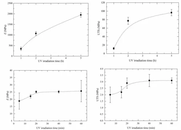
shear. Similar results were obtained for all irradiation times. ... 18 Figure 3.8 – Evolution of Young's Modulus and UTS with increasing irradiation time for PVP films (top row) and PVP
non-woven mats (bottom row). ... 18 Figure 3.9 – Swelling ratio curves for UV crosslinked PVP films with an irradiation period of 1 h (top left), 2 h (top
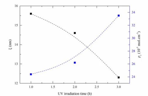
right) and 3 h (bottom middle). ... 19 Figure 3.10 – Evolution of PVP films' mesh size (black line) and crosslinking density (blue line) with increasing UV
irradiation time, considering a swelling time of 5 h. ... 22 Figure 3.11 – (Left) Swelling ratio curves for UV crosslinked membranes with an irradiation period of 5 minutes
(triangle), 30 minutes (circle) and 60 minutes (square). (Right) Variation of the membranes mesh size (black line) and crosslinking density (blue line) with increasing UV irradiation times. ... 23 Figure 3.12 – Evolution of hydrodynamic diameter (Dh) with temperature for simple PNIPAAm microgels (MG),
PNIPAAm microgels with 6 wt.% of AAc (MG6AAc) and PNIPAAm microgels with 10 wt.% of AAc (MG10AAc); variation of microgels' VPTT with adition of AAc. ... 24 Figure 3.13 – SEM micrographs of composite UV crosslinked fibres for 5 (left) and 60 minutes (right). The
micrographs were obtained using a 10k x magnification, a 5 kV electron beam, an aperture size of 30 μm and
xx
Figure 3.14 – TEM micrograph of PVP fibre with confined PNIPAAm-microgels. ... 27 Figure 3.15 – Evolution of Young's Modulus (left graph) and UTS (right graph) with increasing irradiation time for
composite membranes (square) vs PVP non-woven mats (circle). ... 28 Figure 3.16 – Swelling ratio curves for UV crosslinked composite membranes with an irradiation period of 5 minutes
(square), 30 minutes (circle) and 60 minutes (triangle). Variation of the membranes mesh size with varying UV irradiation times (right graph). Swelling ratio of PVP non-woven mats (bottom graph, squares) vs Composite membranes (bottom graph, circles) both UV irradiated for 30 minutes. ... 28 Figure 3.17 – Schematic representing the path of a fluid through a single fibre of an electrospun membrane vs. the
path taken when particles (microgels) are confined inside the fibre. (Adapted from [83]) ... 29 Figure 6.1 – SEM micrographs of PVP UV crosslinked fibres for 10 minutes (top left), 15 minutes (top right), 20
minutes (middle left), 30 minutes (middle right) and 40 minutes (bottom). The micrographs were obtained using a 10k x magnification, a 5 kV electron beam, an aperture size of 30 μm and a WD of 5.8 mm. ... 39 Figure 6.2 – SEM micrograph of PNIPAAm microgels. ... 44 Figure 6.3 – SEM micrographs of composite UV crosslinked fibres for 10 minutes (top left), 15 minutes (top right), 20
minutes (middle left), 30 minutes (middle right) and 40 minutes (bottom). The micrographs were obtained
using a 10k x magnification, a 5 kV electron beam, an aperture size of 30 μm and a WD of 5.8 mm. ... 45 Figure 6.4 – ATR-FTIR spectra of PNIPAAm microgels (black), PNIPAAm microgels with 10 wt.% of AAc (red) and
xxi
List of Tables
Table 6.1 – Reagents and respective quantities used to produce PNIPAAm microgels. ... 37
Table 6.2 – Hydrodynamic and polydispersion index values for synthesized microgels measured by DLS at 24 and 40ºC. All measurements were performed at pH 5.6 ... 37
Table 6.3 – MFD for all variations done during the electrospinning optimization study. ... 38
Table 6.4 – PVP fibres MFD with variation of UV irradiation time. ... 40
Table 6.5 – Tensile tests results for each PVP film's UV irradiation time. ... 40
Table 6.6 – Tensile tests results for each PVP non-woven mats’ UV irradiation time. ... 40
Table 6.7 –v2,s at different swelling times for PVP film samples in shear's parallel direction. ... 41
Table 6.8 –v2,s at different swelling times for PVP film samples in shear's perpendicular direction. ... 41
Table 6.9 – Variation of the molecular weight of the polymer between two neighbouring crosslinking nodes with the UV irradiation time and swelling time for PVP films. ... 41
Table 6.10 – Variation of the mesh size with the UV irradiation time and swelling time of PVP films. ... 42
Table 6.11 – Variation of the crosslinking density with the UV irradiation time and swelling time of PVP films. ... 42
Table 6.12 – Variation of the molecular weight of the polymer between two neighbouring crosslinking nodes for PVP non-woven mats. ... 43
Table 6.13 – Variation of the mesh size and crosslinking density with the UV irradiation time and swelling time for PVP non-woven mats. ... 43
Table 6.14 – Composite fibres MFD with variation of UV irradiation time. ... 44
Table 6.15 – Tensile tests results for each composite membrane's UV irradiation time. ... 47
Table 6.16 – Variation of the molecular weight of the polymer between two neighbouring crosslinking nodes for composite membranes. ... 47
xxiii
Abbreviations
AAc Acrylic Acid
APS Ammonium Persulfate
ATR Attenuated Total Reflectance
Cs Chitosan
DLS Dynamic Light Scattering
EtOH Ethanol
FIB Focused Ion Beam
FTIR Fourier transform infrared HEMA Hydroxyethylmethacrylate
LCST Lower Critical Solution Temperature MBA N,N-methylene bis-acrylamide
MFD Mean fibre diameter
MG Microgel
MG6AAc Poly(N-vinylpyrrolidone) microgel with 6 wt.% of Acrylic acid MG10AAC Poly(N-vinylpyrrolidone) microgel with 10 wt.% of Acrylic acid PEO Poly(ethylene oxide)
PNIPAAm Poly(N-isopropylacrylamide) PVP Polyvinylpyrrolidone
RH Relative Humidity
SBS Sodium Bisulphite
SEM Scanning Electron Microscopy
SFEP Surfactant Free Emulsion Polymerization TCD Tip-to-collector distance
TEM Transmission Electron Microscopy UTS Ultimate Tensile Strength
UV Ultraviolet
xxv
Symbols
Crosslinking density
ε Elongation at break
Flory characteristic ratio
Flory interaction parameter
Length of the bond along the polymer’s backbone tswell Maximum swelling capability time
Mesh size
Molar volume of water
Molecular weight of the polymer chain between two neighbouring crosslinking nodes
Molecular weight of the polymer chains prepared without a crosslinker
Molecular weight of the repeating units
Polymer volume fraction in the swollen state
Specific volume of the polymer
τ Tortuosity
Volume fraction of the chains in the relaxed state
λ Wavelength
Weight of the film/non-woven mat prior to immersion
Weight of the film/non-woven mat after immersion
E Young’s Modulus
xxvii
Motivation and Objectives
The development of new materials/systems that can be tailored for a specific application has always been a topic of interest in materials research. Within a variety of systems, microgels stand out due to their simplicity and versatility. For instance, poly(N-isopropylacrylamide) (PNIPAAm) microgels – which are thermosensitive by nature – when combined with other components can respond to further stimuli such as light and magnetic fields [1, 2].
Furthermore, if we confine microgels inside structures with a high surface to volume ratio as well as high porosity – polymeric electrospun fibres – we can develop not only composite systems that have surfaces with tailored morphologies, but also increase the entire system sensitivity due to the individual properties of each element in the composite.
In the Soft and Biofunctional Materials (SBM) research group, microgels and their confinement inside electrospun fibres are topics that have been explored. In a first work, the preparation of multi-stimuli lower critical solution temperature (LCST)-like magnetic hybrid microgels was reported [3]. The reported microgels successfully maintained the swelling ability of PNIPAAm microgels (LCST ~32 ºC) and preserved the magnetic properties of iron oxide nanoparticles. Marques et al. reports the synthesis and optimization of PNIPAAm/Chitosan stimuli-responsive microgels and further confinement inside poly(ethylene oxide) (PEO)/Water/Ethanol (EtOH) electrospun fibres [4]. The PNIPAAm/Chitosan microgels presented a volume phase transition temperature (VPTT) of approximately 37ºC (for the highest concentration of chitosan) and were successfully confined inside 63 ± 25 nm electrospun fibres,
which presented a ‘bead-on-a-string’ morphology.
Although both works report the successful synthesis of microgels, each presented their own drawbacks. For instance, the microgels reported in [3] present a LCST of approximately 32ºC, which is not suitable for physiological applications where the work temperature is around 37ºC. Besides, the fibre template used for the production of the electrospun composite system was water soluble, which makes it unsuitable for physiological applications [4]. The objective of the present work is the development of composite fibres able to form membranes with potential to tune its surface wettability. We report the study and optimization of poly(N-vinylpyrrolidone) (PVP) as the fibre template for the production of said composite membranes. A UV irradiation treatment was applied to the PVP non-woven mats in order to ensure structure stability in the presence of a solvent (prevent dissolution). Later on, an attempt to confine PNIPAAm-Acrylic acid (AAc) microgels was made – acrylic acid was used to increase the
microgels’ LCST to more physiological values – so to develop a proof of concept of a UV crosslinked composite multifunctional system that could be used as a controlled release mechanism, self-healing, filter, among others. Concerning the optimization of PVP as fibre template, several studies were performed in order to find the optimal electrospinning parameters and UV irradiation times with the final goal of obtaining a membrane that could not only present a somewhat elastic behaviour but also maintain its structural stability. This topic involved the following studies:
Study the influence of electrospinning parameters, such as polymer concentration, process flow-rate,
applied voltage and tip-to-collector distance in the resulting non-woven mats;
Comparative study of non-woven mats vs. films to evaluate the morphological, mechanical and swelling
xxviii
For the development of the composite multifunctional system, this topic was divided into the following sub-objectives:
Synthesis and characterization of PNIPAAm-AAc microgels;
Production of composite membranes using a simple, cost-effective and versatile technique – Colloidal Electrospinning;
Study of morphological, mechanical and swelling properties of the composite membranes in order to
1
1
Introduction
1.1
Composite materials
Materials engineering has always focused on the assembly of materials with enhanced properties that can serve multiple purposes. By combining two or more physically and/or chemically distinct materials, a new product with characteristics that are not presented by any of its components in their isolated stated can be manufactured. These
‘new’ materials are commonly called composite materials [5].
The applications of composite materials are not limited to the automotive or aircraft industries [6-8].Composite materials are necessarily multifunctional materials, and the strong growth in the use of composites has been greatly influenced by multifunctional design requirements [9]. Over the last years, research has been made in order to produce systems that can release drugs [10, 11] or even self-heal [12] when in presence of a specific stimuli. For instance, Ke et al reported on the production of a novel smart system based on poly(D,L-lactic-co-glycolic acid) (PLGA) hollow microspheres that can deliver anticancer drug into tumour cells using the change in pH values of the tumour cell as the triggering stimulus [10].
When considering the production method of these stimuli-responsive multifunctional systems, electrospinning technique comes as an advantage since it not only enables the facile incorporation of the active sites [13], but also enhances the sensitivity of the entire system to external stimuli due to the extremely large surface area and porosity of the fibres (polymeric matrix) [14, 15].
1.2
Colloidal Electrospinning
Electrospinning is a cost-effective, simple and versatile process capable of forming polymer fibres in the submicron range with high surface to volume ratio, flexibility and tuneable porosity [16, 17]. This process works by applying a high electric field to the droplet of a fluid – solution or melt – that is coming out from the tip of a needle, which acts as one of the electrodes. The electric field leads to the droplet’s deformation and posterior ejection from the tip of the cone in the form of a charged jet, which is then accelerated towards a counter-electrode, leading to the formation of continuous fibres [16]. The fibres resulting from the electrospinning process have been used in a variety of applications, ranging from sensors to drug delivery and tissue scaffolds [18-21].
Although electrospinning is a simple process, the fibre’s surface topography, morphology and orientation are highly
dependent on a number of parameters, which can be grouped in three different categories: i) solution parameters, ii) process parameters and iii) environmental conditions [17]. For instance, when the polymer’s concentration is very low its viscosity is not enough to guarantee the entanglement of the polymeric chains, phenomenon required for fibre
formation. This leads to ‘electrospraying’, which results in the formation of particles instead of fibres [22]. Other parameters, such as flow rate, applied voltage, tip-to-collector distance and relative humidity have great influence on the electrospinning process. Those will be further studied and discussed in Section 3.1.1.
2
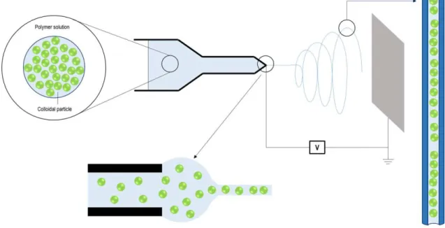
the same purpose [24]. Moreover, co-axial electrospinning does not guarantee the production of core-shell fibres due to the influence of the flow rate of the inner and outer solutions and the viscoelasticity of the polymers involved [25]. Furthermore, this approach is environmentally friendly since it enables the minimization of the amount of organic solvents used during the production process [26]. Figure 1.1 depicts a colloidal solution and how the different components interact in order to form a core-shell fibre.
Figure 1.1 – Schematic illustration of a colloidal electrospinning set-up. The green circles represent the colloidal phase, which can be either organic or inorganic compounds. (Adapted from [13])
One of the main advantages that colloidal electrospinning possesses is the different fibre morphologies that can be obtained, regarding dispersed phase placement inside the fibre. Taking this in consideration, there are two main types of morphologies that appear in colloidal electrospinning fibres: ‘bead-on-a-string’ [27] and ‘core-shell’ [28]. In order to best comprehend these morphological structures, it is necessary to consider the dispersed phase evolution during the electrospinning process [29]. Regarding the ‘bead-on-a-string’ structures, when the emulsion flows through a long capillary and forms the expected accelerated bending fluid jets, the dispersed phase has the tendency to accumulate in the centre of the liquid along the direction of fluid during its flight in the air. This helps the microbeads to settle in the centre of the fibre, rather than on the surface [27]. If the electric field is too high, the beads will suffer higher elongation, displacing them from the centre and making them settle closer to the fibre’s
surface, giving rise to ‘spindle-like’ structures [27]. As for the core-shell fibres, the viscosity difference between the particles and the polymeric matrix – core and shell respectively – plays an important role. During the electrospinning process, the particles are stretched into elliptical shapes in the fibre’s axial direction, giving rise to a continuous core [30]. If the viscosity of the particles vs.viscosity of the polymer matrix is not correct, particles do not fully elongate and break up, leading to the formation of beads instead of a continuous core [30, 31].
3
microgels, which can act as drug carriers, into polymeric fibres by means of colloidal electrospinning. This set-up would originate multifunctional fibres with fast thermosensitive behaviour and tuneable surfaces. Few studies report the confinement of microgels inside polymeric fibres. Díaz et al. produced composite fibres of PNIPAAm-based microgels using PVP as fibre template, obtaining fibres with a mean diameter of 0.9 μm and a water uptake of 17 times their dry weight [32]. PEO fibres with confined PNIPAAm-chitosan (PNIPAAm-Cs) microgels with a mean diameter of 63 nm and bead-on-a-string morphology were reported by Marques et al. [4].
1.3
Thermosensitive microgels
Microgels are intramolecular crosslinked polymer particles of colloidal size (10 – 1000 nm) that swell in the presence of a suitable solvent [3, 33, 34]. Depending on their composition, the interactions with the solvent can be triggered/controlled via external stimuli, such as temperature, pH, magnetic and electric field and even light. This feature makes polymeric microgels materials of interest for biomedicine, sensing and imaging applications [35-38]. Thermosensitive microgels are colloidal particles that undergo a conformational change under a specific temperature range, when in contact with suitable solvents. One of the most studied is a negative temperature-sensitive polymer called PNIPAAm, which has a transition temperature, in aqueous medium, near human body temperature (~ 32 ºC). This temperature is known as LCST. The thermoresponsive behaviour showed by PNIPAAm originates from the interactions between its hydrophilic and hydrophobic groups – acrylamide and isopropyl groups respectively – as well as from hydrogen bonding [39]. At temperatures below the LCST, hydrogen bonds between hydrophilic segments of the polymer chain and water molecules dominate, leading to enhanced dissolution in water. This interaction makes the PNIPAAm chains to obtain a hydrated/open state, called ‘coil’. However, with the increase of temperature the hydrophobic interactions between hydrophobic groups become stronger and hydrogens bonds – N-H or C=O – become weaker, which leads to the collapse of the polymer molecule [40]. After collapse, the molecule obtains a
more compact/cohesive state, commonly denominated as ‘globule’. The transition from an open to a more collapsed
state is called ‘coil-to-globule’ transition [41]. This ‘coil-to-globule’ transition is also reflected in the behaviour of crosslinked PNIPAAm microgels. In this case, PNIPAAm microgels transit from a swollen state – related to their hydrophilic nature – to a deswollen/collapsed state. The temperature responsible for the volume change is called Volume Phase Transition Temperature (VPTT) and may or may not be the same as the LCST [42, 43].
4
1.4
Promissing hydrogels from polyvinylpyrrolidone
Since the pioneering work of Wichterle and Lim in 1960 [49] in crosslinked Poly(2-hydroxyethyl methacrylate) (Poly-HEMA) hydrogels, these materials have been vastly explored over the years due to their hydrophilic character and biocompatibility [50-54]. Hydrogels are hydrophilic crosslinked polymer networks which can absorb water several thousand times their dry weight in water and retain their structure integrity. These polymeric networks contain covalent bonds produced by the reaction of one or more co-monomers, physical crosslinks due to chain entanglements, association bonds including hydrogen bonds or strong van der Walls interactions between chains, or crystallites bringing together two or more macromolecular chains [55, 56]. If two or more polymeric chains are held together by chain entanglements and/or secondary forces (e.g.: hydrogen bonds) the hydrogel is called ‘physical’ or
‘reversible’. Physical gels are not homogenous since clusters of molecular entanglements, or hydrophobic domains, can give rise to inhomogeneities [57]. When the polymeric network of a hydrogel is covalently crosslinked, the
hydrogel is called ‘chemical’ or ‘permanent’. This type of hydrogel can be produced by either in situ monomer polymerization – which requires the presence of a bifunctional monomer – or by crosslinking the preformed macromolecule [58], making it more stable than physical hydrogels. When considering a chemical hydrogel for biomedical applications, it is preferable to produce it using a crosslinking mechanism instead of in situ monomer polymerization, in order to eliminate any residual monomer that could be potentially toxic.
PVP is a neutral hydrophilic water-soluble polymer with low toxicity and high biocompatibility with living tissues, capable of binding reversibly to various molecules (dyes, metals and some polymers) in solution [59, 60]. These characteristics, allied with the fact that PVP has a strong tendency to form complexes with smaller molecules, makes this polymer a strong candidate to produce drug delivery systems [61].
This polymer is very effective as a hydrogel due to the capability of incorporate water in its network when crosslinked, which is something that does not occur when PVP is in its linear form [62]. Traditionally, PVP hydrogels are obtained by either the monomer polymerization or crosslinking of the preformed polymer chains. Like any hydrogel, PVP hydrogels if synthesized via monomer polymerization could contain toxic residual monomers, which would need expensive and time-consuming purification [63]. Taking that in consideration, crosslinking the preformed polymer chains is more promising. In 1990 Rosiak et al. [64] proposed a methodology of hydrogel dressing production based on high-energy irradiation of PVP aqueous solutions, resulting in hydrogels with no potentially toxic residual monomers. The problem with this method is the use of high-radiation sources, which are very expensive and not easily available. A solution to this problem is the use of Ultraviolet (UV) radiation, not just because is cheaper than high-energy radiation, but also due to the extremely short time required for reliable gel formation [60]. During UV irradiation, the pyrrolidone substituents and cyclic amides on the PVP chains generate macroradicals – produced by UV direct photolysis of PVP – whose recombination could lead to intermolecular crosslinking PVP [65]. The results of
5
Figure 1.2 – Chemical structure of N-vinylpyrrolidone monomer and effect of UV irradiation on PVP chain with consequent intramolecular crosslinked PVP (adapted from [65]).
Normally hydrogels are prepared in the form of dense films, which end up being impermeable to air and liquid and have lower surface area when compared to porous materials. One way to overcome these obstacles is to create fibrous hydrogels: polymeric hydrogel meshes with high air/liquid permeability and elevated water absorbance capacity [66]. These structures, which are prepared mostly by electrospinning, are a topic of interest because of the large surface area and highly porous structure [67, 68], making them a suitable material for wound dressing [69]. In previous works done in SBM research group [3, 4], microgels and composite fibres have already been explored. Although, those works presented some drawbacks, which lead to the need to re-evaluate the used systems and further optimize them so that a stable system with various applications can be conceived. Taking into consideration the versatility of microgels and the structural stability acquired by PVP when crosslinked using UV irradiation, a composite multifunctional system can be design.
7
2
Materials and Methods
2.1
Materials
N-isopropylacrylamide (NIPAAm, Aldrich Chemistry, 97%) was used as a monomer and N,N-methylene bis-acrylamide (MBA, Aldrich, 99%) as crosslinker, ammonium persulfate was chosen as initiator (APS, Sigma-Aldrich, 99%) and sodium bisulphite (SBS, Acrös Organics) as catalyst. All reagents were used as received without any further purification. Acrylic acid 90% (Alfa Aesar) was used in order to study the effects in the microgels’ LCST.
2.2
Synthesis of PNIPAAm microgels
PNIPAAm and PNIPAAm-AAc crosslinked microgels were synthesized by means of surfactant-free emulsion polymerization (SFEP) method. All polymerizations were conducted in a 100 mL three-necked round flask equipped with a reflux condenser, a mercury thermometer and a nitrogen inlet/outlet. The weight percentage of crosslinker, initiator and catalyst was 5%, 10% and 5% respectively. NIPAAm and MBA solutions, 50 μg.mL-1 and 2.5 μg.mL-1 respectively, were mechanically stirred at 400 – 500 rpm for 5 minutes and purged with nitrogen for 30 minutes. The
reaction was initiated by heating the flask up to 70ºC (above PNIPAAm’s LCST) with the immediate addition of the
APS solution. After 1 h the catalyst solution was added. The reaction proceeded for 4 hours at constant temperature and nitrogen atmosphere. The obtained microgel dispersions were dialyzed against distilled water using a dialysis Spectra/Por molecular porous membrane (MWCO: 12 – 14,000) for a week. Finally, the microgels were freeze-dried (VaCo 2, Zirbus) in order to guarantee long term stability.
For the preparation of PNIPAAm-AAc microgels, different weight percentages of acrylic acid were dissolved in water, namely 6% and 10%. The acrylic acid solution was added after the NIPAAm solution and the polymerization process proceeded as previously mentioned. The quantities used to synthesize both PNIPAAm and PNIPAAm-AAc microgels, as well as the respective hydrodynamic diameters and polydispersion indexes, can be consulted in Table 6.1 and Table 6.2 respectively, available on Section 6.1 of the Supporting Information
2.3
Colloidal-electrospinning
2.3.1
Polyvinylpyrrolidone solutions
8
2.3.2
Colloidal-electrospinning experiments
The electrospinning experiments were conducted using a high voltage power supply (Glassman High Voltage, EL, USA), a digitally programmed syringe pump (kdScientific) and a tin foiled cover as collector. The solutions were loaded into a 5 mL syringe fitted with a 23-gauge blunt tip needle and mounted onto a syringe pump programmed to deliver said solutions with a flow of 0.3 and 1 mL.h-1. The process was carried out with two different applied voltages (10 and 15 kV) and two different tip-to-collector distances (TCD), namely 12 and 18 cm, in a climatic cabin with a relative humidity of 30 – 40%, in order to ensure solvent’s fast evaporation, and controlled temperature, close to
25ºC, well below the microgel’s LCST. Electrospinning ran for approximately 2 h and the resulting non-woven fibre mat was dried for 24 h, in order to remove any remaining solvent.
As for the colloidal electrospinning, the parameters used result from the electrospinning optimization study: 14 wt.% PVP/EtOH polymeric solution, 15 kV of applied voltage, 12 cm TCD, relative humidity between 30 – 40% and temperatures ranging from 20 – 25ºC. The flow rate used was 0.7 mL.h-1, which is lower than the optimized (1 mL.h -1). This change will be further discussed in the Results and Discussion Section.
2.4
PVP film preparation
A solution of 40 wt.% of PVP in ethanol was shear cast into several films using an Automatic Film Applicator (Braive Instruments) fitted with a 1 mm adjustable Filmographe baker with a shear rate of 1.25 mm.min-1. The thin films were dried for 48 h in order to fully evaporate the solvent.
2.5
UV crosslinking method
PVP thin films, membranes and composite membranes were crosslinked with 254 nm ultraviolet light in a BIO-LINK® irradiation system. The films were irradiated for 1, 2, 3 and 5 h, while the membranes were irradiated for 5, 10, 15, 20, 30, 40 and 60 minutes.
2.6
Characterization techniques
Scanning electron microscopy (SEM) technique was used in order to evaluate the morphology of the obtained fibres. For the electrospinning optimization study, the samples were prepared with a gold coating and analysed using a Zeiss DSM 962 scanning electron microscope. As for the membranes that were produced after the optimization study, their morphology was studied using a SEM apparatus fitted with a Carl Zeiss Auriga CrossBeam system (SEM-FIB). A small piece of fibre mat was fixed on carbon tape and then mounted on a support and sputtered with a thin layer of gold/palladium using a Q300T D Quorum sputter coater. The diameter and distribution of the overall electrospun fibres were determined using ImageJ software.
9
Tensile tests were performed in order to study the non-woven mats and film’s mechanical response. Non-woven mats, films and colloidal membranes’ samples were cut into 10x5 mm rectangles and mounted onto a pair of clamps and stretched at a speed of 0.1 mm.min-1.
11
3
Results and Discussion
3.1
Polyvinylpyrrolidone membranes
The focus of this dissertation is the optimization of the polymeric matrix, PVP, in order to obtain fibres with a monodisperse distribution of diameters as well as a minimum mean fibre diameter. To do so, a study where electrospinning parameters such as polymer solution concentration, process flow rate, applied voltage and tip-to-collector distance (TCD) were varied in specific ranges was performed. For this electrospinning process, temperature was kept between 20 – 25ºC and the RH between 30 – 40%, since these are the ranges that guarantee the formation of PVP fibres [71].
3.1.1
Optimization of electrospinning process
Like previously stated, the diameter of the polymeric fibres can be influenced by several parameters, which are normally gathered into three groups: i) solution parameters, ii) process parameters and iii) environmental conditions. For instance, both polymer’s concentration and process flow rate influence the fibre’s diameter in the same manner: with the decrease of concentration/flow rate, thinner fibres can be obtained [72]. As for the applied voltage, fibres with smaller diameters can be obtained when working with stronger electric fields. However, when working with high electric field the probability of beads formation is higher [73]. Another parameter of great influence in the
electrospinning process is relative humidity (RH), which affects the solvent’s evaporation and thus the formation of pores on the fibre surface. De Vrieze et al studied the effect of temperature and humidity on PVP fibres and concluded that, at higher RH the absorption of the surrounding water causes slower solidification, longer jet elongation time and therefore lower fibre diameters [71]. However, over 60% RH, the fibres start to fuse with each other, resulting in larger diameters.
3.1.1.1 Influence of polymer concentration
Two different solutions of PVP dissolved in ethanol – 10 and 14 wt.% – were prepared and electrospun. For this part of the study, the flow rate, applied voltage and tip-to-collector distance constant were constant – 0.3 mL.h-1, 15 kV and 18 cm respectively – in order to see just the effect of the solution’s concentration. The resulting fibres and respective mean fibre diameters (MFD) are depicted in Figure 3.1. The MFD for all the parameters’ variations can be consulted in Table 6.3, available at Section 6.2 of the Supporting Information.
12
electrospinning of silica/PVP (SiO2/PVP) composite nanofibers, where PVP fibres were obtained using 9, 10 and 11 wt.% PVP solutions, with the 11 wt.% PVP solution originating the nanofibres with the highest diameter [75].
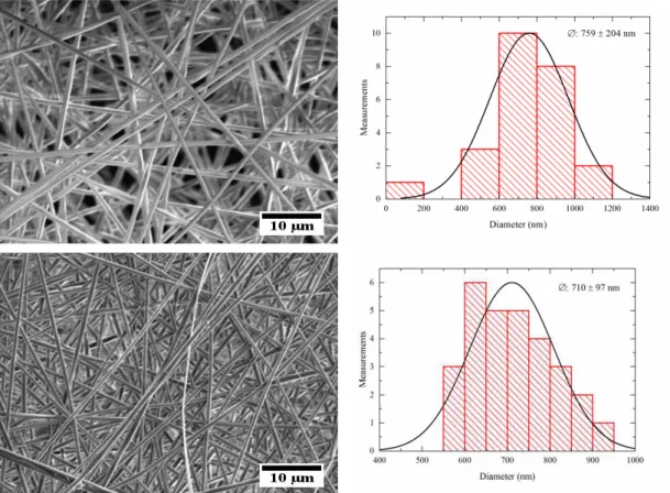
Figure 3.1 – SEM micrographs of PVP non-woven mats, and respective MFD, electrospun from 10 wt.% (top) and 14 wt.% (bottom) PVP/EtOH solutions. The electrospinning process was conducted using a 0.3 mL.h-1 flow rate, 15 kV and 18 cm TCD. All scale bars represent 10 μm.
Nevertheless, the solution with a concentration of 10 wt.% formed fibres with beads (which was not desired). The remaining influencing factors (flow rate, applied voltage and TCD) in this optimization were all performed using the 14 wt.% solution, which did not present any sort of defects, although the mean fibre diameter of the fibres is higher (Figure 3.1)
3.1.1.2 Influence of process flow rate
In this case, two different process flow rates where studied – 0.3 and 1 mL.h-1– while the polymer concentration, the applied voltage and the TCD were kept constant at 14 wt.%, 10 kV and 12 cm respectively.
13
Figure 3.2 – SEM micrographs of PVP non-woven mats, and respective MFD, electrospun from a 14 wt.% PVP/EtOH solution with a flow rate of 0.3 mL.h-1 (top) and 1 mL.h-1 (bottom). The electrospinning process was conducted using 10 kV and 12 cm TCD. All scale bars represent 10 μm.
As it was expected, MFD increases with the increasing flow rate (759 ± 204 nm for 0.3 mL.h-1 to 1695 ± 239 nm for 1 mL.h-1). Since both flow rates enabled the production of electrospun fibres, it can be said that the lower limit at which the Taylor cone can be stabilized was not exceeded. Consequently, depending on the desired MFD, both flow rates can be used to successfully produce PVP electrospun fibres.
3.1.1.3 Influence of applied voltage
In order to study the influence of the applied voltage on the fibre’s diameter, 10 and 15 kV were applied to the tip of the needle during the electrospinning process. Once again, all the other parameters remained constant; in this case, the chosen polymer concentration was 14 wt.%, the flow rate 1 mL.h-1 and the TCD was 12 cm. Figure 3.3 shows the results for the variation of the applied voltage.
When high voltages are applied, the polymer jet suffers a greater stretching due to the greater columbic forces and stronger electric field, which leads to thinner fibres. However, applying lower voltages results in the reduction of the
polymer jet’s acceleration, which increases its time of flight and consequently its stretching ability [76].
14
Figure 3.3 – SEM micrographs of PVP non-woven mats, and respective MFD, electrospun from a 14 wt.% PVP/EtOH solution with an applied voltage of 10 kV (top) and 15 kV (bottom). The electrospinning process was conducted using a flow rate of 0,3 mL.h-1 and 12 cm TCD. All scale bars represent 10 μm.
3.1.1.4 Influence of tip-to-collector distance
The variation of the tip-to-collector distance mainly affects the fibre’s time of flight, which consequently influences the
solvent’s evaporation. If the flight time is not enough, there will be an incomplete evaporation of the solvent that will lead to the formation of fused fibres [75]. As for the MFD it usually increases with the increasing TCD, although it has been reported that it is possible to obtain thinner fibres with higher TCD [76].
The TCD has a great influence on the area of the collected fibre mat which can vary depending on the application in mind. During the electrospinning process, the fibre jet that is accelerated from the polymer droplet starts in a straight line-like shape and progressively begins to bend, in order to reduce the density of surface charge, to promote jet extension and increase surface area. This ‘unstable whipping’ creates a cone perpendicular to the collector’s plane, forcing the deposited fibre mats to take a circular shape (base of the cone) [75]. Depending on the TCD, and maintaining the polymer concentration, applied voltage, flow rate and deposition time constants, one can obtain thinner or thicker fibre mats, using lower or higher TCD respectively.
15
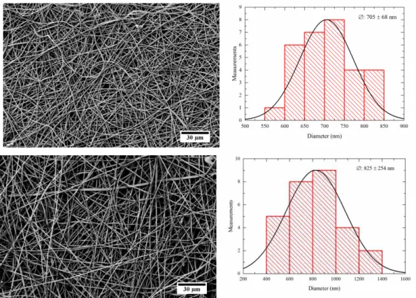
Figure 3.4 – SEM micrographs of PVP non-woven mats, and respective MFD, electrospun from a 14 wt.% PVP/EtOH solution with a TCD of 12 cm (top) and 18 cm (bottom). The electrospinning process was conducted using a flow rate of 1 mL.h-1 and 15 kV.
After studying the influence of the target-to-collector distance, a small increase in MFD was observed with the increase of TCD (705 ± 68 nm for 12 cm TCD and 825 ± 254 nm for 18 cm TCD). The non-woven mat produced with 12 cm TCD appears to be denser than the 18 cm TCD one. Since the 12 cm one is closer to the tip of the cone (confirmed by the unstable whipping of the accelerated jet), and since both mats were electrospun for 15 minutes, for the same amount of time the collector that was closer to the cone tip enable the deposition of a denser non-woven mat. Moreover, the electrospun non-woven mats produced using a TCD of 18 cm have a wider dispersion of diameters, from 400 nm to 1400 nm. Therefore, the TCD of 12 cm is more appropriate for the desired optimization. Like it was previously said, the study that was made to obtain the more monodispersed distribution of fibres was conducted by varying all the parameters, although not all combinations are presented in this chapter. Table 6.3 on Section 6.2 of the Supporting Information contains all the MFD resulting from this study.
After the optimization process, the most suitable parameters were determined to be a 14 wt.% PVP/EtOH solution, flow rate of 0.3 and 1 mL.h-1, 10 or 15 kV of applied voltage, 12 cm TCD, a RH range of 30 – 40% and process temperature between 20 to 25ºC.
3.2
Process-dependent comparative study: non-woven mats
vs.
films
16
toxic residual monomers, they are expensive and not easily available. In this dissertation PVP was crosslinked by means of UV irradiation, a green and cost-effective technique that allows the increase of the system’s structure stability. To do so, the non-woven mats, cut into 10x5 mm samples, were placed inside a BIO-LINK® crosslinker and irradiate at 254 nm, which is found within the PVP absorption spectrum (200 – 280 nm). When exposed to this range of radiations, pyrrolidone substituents and cyclic amides on the PVP chains generate macroradicals whose recombination leads to intermolecular crosslinked PVP. The achieved crosslinking degree will depend in the irradiation dose and hence in the time that the non-woven mats are irradiated.
Therefore, in order to determine the most suitable conditions (irradiation time) to crosslink the PVP non-woven mats, and to better understand the behaviour of UV crosslinked PVP, a process-dependent comparative study was conducted: non-woven mats vs. films. For the comparative study, PVP films were prepared from a 40 wt.% PVP/EtOH solution by shear casting method (v = 1.25 mm.min-1) and left to dry for 48 h to guarantee complete solvent evaporation. The non-woven mats were irradiated for 5, 10, 15, 20, 30, 40 and 60 minutes, whereas the shear-casted PVP films were irradiated for 1, 2, 3 and 5 h. The difference between the irradiation time of the non-woven mats and the films can be explained by the high surface area to volume ratio of the mats: a higher ratio means more area available to be crosslinked, hence less irradiated time is required to achieve the same goal.
3.2.1
UV crosslinking influence in morphology
In order to study the influence of UV irradiation in morphology, SEM micrographs were taken for both non-woven mats and films. Figure 3.5 and Figure 3.6 depict the evolution of the non-woven mats and films morphologies with increasing irradiation time.
Figure 3.5 – SEM micrographs of PVP fibres crosslinked for 5 minutes (left) and for 60 minutes (right) under UV radiation. The
micrographs were obtained using a 10k x magnification, a 5 kV electron beam, an aperture size of 30 μm and a WD of 5.8 mm.
For the non-woven mats morphology (Figure 3.5), there are no great changes in the MFD with the increase of irradiation time, since all non-woven mats have a MFD of approximately 830 nm (for full data the reader can consult Table 6.4 in Section 6.3 of the Supporting Information). However, with 60 minutes of UV irradiation there are some
visible cracks on the fibres’ surface, possibly indicating excessive irradiation time.
17
are cracks throughout the entire film’s surface (Figure 3.6, right micrograph), which may be an indicator of excessive irradiation time.
Figure 3.6 – SEM micrographs of PVP films crosslinked for 1h (left) and 5 h (right) under UV radiation. The micrographs were obtained using a 2k x magnification, a 2 kV electron beam, an aperture size of 30 μm and a WD of 5.6 mm.
In order to better understand the influence of the UV irradiation treatment, an indirect evaluation of the crosslinking method was performed by studying the mechanical properties of both non-woven mats and films, as well as their swelling properties.
3.2.2
UV crosslinking influence in the mechanical properties
PVP films – with a mean thickness 22 ± 3 μm– were treated with different UV exposure times, (1, 2 and 5 h). For each irradiation time samples cut on the parallel and perpendicular directions to the shear cast direction were tested,
being the results for Young’s Modulus (E), Ultimate Tensile Strength (UTS) and Elongation at break (ε) presented in Table 6.5 available on Section 6.4 of the Supporting Information.
When a film is shear-casted, the polymer chains get aligned in the direction of the shear vector, which results in a polymeric film where polymer molecules have a preferential orientation. This preferential orientation may have some influence on the film’s mechanical properties. To infer on the effects of said preferential orientation, the PVP films’ mechanical properties were studied using samples cut in both the parallel and perpendicular directions to the shear vector. After the assessment of the mechanical properties, it was found that there are no great differences between the samples stretched in the parallel and perpendicular to the shear direction (Table 6.5, Section 6.4 at Supporting Information). Figure 3.7 shows two representative curves of the performed mechanical tests.
Concerning the irradiation time, it was macroscopically observed that above 5 h of irradiation the films turned yellow, which indicates that PVP has suffered photodegradation [59]. Therefore, three different times were studied, namely 1, 2 and 5 h. One of the effects that photodegradation has in PVP is the increase of the elongation at break. If a polymer is irradiated for long periods of time it suffers photodegradation, which leads to the formation of small molecular groups that act as plasticisers [77]. These plasticisers are responsible for the increase of elongation (0.67 ± 0.14% for 1 h UV irradiation to 2.0 ± 0.37% for 2 h UV irradiation) as it is shown in Table 6.5. Although, when
passing from 2 h to 5 h irradiation time, the elongation at break decreases, possibly due to oxidation, destruction of the crystal regions or the formation of new order range [77].
To comprehend the differences of the polymer matrix – non-woven mats and films – both the evolution of the
18
Figure 3.7 – Stress/Strain curves for PVP films with 2 h UV irradiation in parallel and perpendicular directions to the shear. Similar results were obtained for all irradiation times.
19
By analysing the plots in Figure 3.8 it is possible to say that, for the irradiation times studied, the polymeric matrix shows different mechanical behaviours for the different preparation techniques (shear casting vs. electrospinning). Regarding the films behaviour (Figure 3.8, top row) both Young’s Modulus and UTS increase with increasing irradiation times (Table 6.6 on Section 6.4 of the Supporting Information). This increase could be related to an increase of crosslinking degree, but further studies with intermediary and higher irradiation times should be performed in order to better assess this behaviour. As for the non-woven mats (Figure 3.8, bottom row), an
equilibrium for the Young’s Modulus and the UTS is reached after 20 minutes of irradiation time, which means that
irradiating the mats for more than 20 minutes does not bring a visible advantage to the system’s mechanical
properties. Although the mechanical properties do not change, the morphology is in fact affected with the increase of irradiation time (appearance of cracks for 60 minutes of UV irradiation time).
3.2.3
UV crosslinking influence in the swelling properties
In order to study the influence of the UV irradiation time in the crosslinking process of the PVP films, their swelling properties were evaluated. For that, 6 rectangular samples (10x5 mm) of each irradiated film – 3 in the parallel and 3 in the perpendicular directions of the shear – were immersed in water for 0.5, 1, 2, 3 and 5 h. Between each immersion time the water was changed in order to eliminate any possible non-crosslinked polymer chains resulting from the dissolution. Swelling ratio curves were plotted to see when the samples would reach an equilibrium state with the surrounding medium (Figure 3.9).
20
The swelling ratio (Q) for each point in the curves was obtained using Eq. (3.1)
(3.1)
where ws is the weight of the film after immersion and wd the weight of the film prior to immersion.
By analysing the swelling ratio curves plotted in Figure 3.9, it is observed that all the samples reached their maximum swelling capability at around 1 h, which from now on will be referred to as tswell. The variation of the irradiation time did not cause significant differences between samples of the same group – samples with same irradiation time but different shear direction alignment. For instance, the sample with 2 h of irradiation has maximum swelling ratio values of approximately 31 and 32 (parallel and perpendicular alignment to shear direction, respectively).
The UV crosslinking process effect on the polymer’s network can also be studied using the swelling ratio curves.
Regarding the 1 h irradiated film, the film’s swelling capability starts to slowly decrease after tswell, which may indicate that the polymer is being dissolved (Figure 3.9, top left). This gradual decrease leads to the conclusion that 1 h of UV irradiation may not be enough to fully crosslink the PVP films, allowing the dissolution of the polymer as reflected in the decrease of swelling ratio. The 2 h irradiated film has a different behaviour than the 1 h one: after tswell, the 2 h film has a small decrease in swelling capability, followed by a stable period that last for approximately 3 hours. This stable period indicates that the film reached equilibrium with its surrounding medium, meaning that no more water is neither penetrating nor leaving the polymer’s network. Approximately 3 h after tswell is observed, a small decrease in swelling capability occurs, indicating once again the polymer’s possible dissolution (Figure 3.9, top right). As for the 3 h irradiated film, it presents a higher equilibrium period (up to 5 h), which indicates that out of the three irradiation times tested, this was the one that was able to better crosslink the PVP films.
From the analysis of the swelling properties it is possible to calculate the network mesh size, which is directly related to the crosslinking degree of the polymer network after UV crosslinking process by the application of the Equilibrium Swelling theory [78]. When studying a hydrogel’s behaviour in a liquid medium there are three parameters that stand out for the characterisation of the network structure: i) polymer volume fraction in the swollen state (v2,s), ii) molecular
weight of the polymer chain between two neighbouring crosslinking nodes (Mc) and iii) mesh size (ξ). The polymer
volume fraction in the swollen state is a measure of the amount of fluid that the hydrogel’s network can absorb and
retain. The molecular weight between two neighbouring crosslinking nodes measures the degree of crosslinking of the polymer, whether is chemical or physical crosslinking. Lastly, the mesh size gives information about the available space for fluid diffusion between the macromolecular chains. Both Mc and mesh size can only be average values due
to the fact that the crosslinking process is completely random [55]. These three parameters are related to one another and can be determined with the help of the Equilibrium swelling theory.
The Equilibrium Swelling theory, first proposed by Paul Flory and John Rehner [78], states that a crosslinked polymer gel, when immersed in a fluid and allowed to reach equilibrium with its surroundings, is subject only to two opposing forces: the thermodynamic force of mixing and the retractive force of the polymer chains. When factoring the influence of these two forces, the molecular weight between two neighbouring crosslinking nodes of a neutral hydrogel prepared in the absence of a solvent can be calculated, like is showed in Eq. (3.2).
![Figure 1.2 – Chemical structure of N-vinylpyrrolidone monomer and effect of UV irradiation on PVP chain with consequent intramolecular crosslinked PVP (adapted from [65])](https://thumb-eu.123doks.com/thumbv2/123dok_br/16693240.743723/33.892.174.731.117.504/figure-chemical-structure-vinylpyrrolidone-irradiation-consequent-intramolecular-crosslinked.webp)