Non Resistive Analysis of Rotational Instabilities
in FRC and the Unicamp TC-1 m=4 Results
M. A. M. Santiago
Instituto de Fsica, Universidade Federal Fluminense 24210-340, Niteroi, Rio de Janeiro, Brazil
A. S. Assis
Instituto de Matematica, Universidade Federal Fluminense 24020-100, Niteroi, Rio de Janeiro, Brazil
C. A. de Azevedo
Instituto de Fsica, Universidade do Estado do Rio de Janeiro 20550-013, Rio de Janeiro, RJ, Brazil
P. H. Sakanaka, M. Machida, E. Aramaki, L. A. Berni,
D. O. Campos and R. T. Farias
Instituto de Fsica `Gleb Wataghin' Universidade Estadual de Campinas, UNICAMP
13083-970, Campinas, S~ao Paulo, Brazil Received September 30, 1997
Ideal one dimensional MHD (non-resistive) equations are used to study the rotational in-stability in eld reversed conguration plasmas. Instead of using resistive boundary layer analysis, the eigenmode non hermitian equations are solved on the complex !-plane us-ing a numerical code constructed usus-ing \Mathematica". We take into account the plasma compressibility and compare our results with the Compact Torus (TC-1) experiment of the Universidade Estadual de Campinas (UNICAMP), which is presented here. The m = 4 rotational mode observed in TC-1 is used to verify the consistency of our model.
I. Intro duction
The prospect of eld reversed conguration (FRC) devices to be competitive with other fusion devices re-lies on the understanding of the stability properties[1]-[3]. Frieman and Rotenberg [4] developed the original perturbation theory for a owing equilibrium includ-ing the plasma compressibility. We use their basic op-erator equation to study the rotational mode in eld reversed conguration. Other previous work are also concentrated on rotational modes [5]-[8]. According to boundary layer analysis [9],[10], the plasma is governed by ideal MHD with real frequency ! on both sides of the singular layer r0 where the equilibrium magnetic
eld vanishes. To overcome the accumulation point of the frequency spectrum of the eigenmode, resistivity was introduced in the boundary layer which leads to a growth rate strictly related to resistivity. But previous works [5],[6], indicated that resistivity is not relevant to analyse rotational modes.
II. Equilibrium and perturbed equations
We consider a reversed eld -pinch conguration with axial magnetic eld and azimuthal rotation . All variables depend onronly. The equilibrium proles are given by (see Figures (1) - (3))
~
B = B
z( r)^z; where B
z is the magnetic eld and is modeled, to be realistic with the TC-1 machine, as
B z(
r) = + (1,)tanh[(0:55r) 4+ (0
:55r) 2]
;(1) and
=,tanh[(0:55) 4+ (0
:55) 2]
=(1,tanh[(0:55) 4+ (0
:55) 2])
;
(r) = fexp[,(r =2) 8] + 0
:05g=1:05; (2) where is the mass density,
~
v = v(r)^=r^ ; (3) ~
v is the velocity eld, and the rotational frequency is assumed to be constant.
We use the non resistive MHD and Maxwell equa-tions, which are given by
d~v dt
= ,rp+ ~ J ~ B; (4) @ @t
=,r(~v); (5)
and
@ ~ B @t
=r(~v ~
B); (6)
with r ~
B =
~
J, where ~
J is the current density, p=
=const,
is the ratio of specic heats, and r
~ B= 0.
In equilibrium (@ @t
0), we obtain d
dr (p+B
2 z
=2) = 2
r: (7)
We use the Lagrangian representation, linearize the equations and introduce the displacement vector ~
, which is considered a small quantity given by
~ r = ~r
0+ ~ (~r
0
;t) (8)
where ~r
0 describes the equilibrium trajectory and ~
(~r 0
;t) describes the displacement from equilibrium, and consider the equilibrium quantities as time inde-pendent.
Following the linearization of the basic equations described in [4] we obtain the non hermitian linearized equation of motion in the form
( @
2~ @t
2) + 2 ~vr(
@ ~ @t ) = ~ F( ~
); (9)
where ~ F(
~
) =r(pr: ~ + ~ :rp, ~ B: ~ Q) + ~ B:r ~ Q+ ~ Q:r ~ B+r:(
~
~v:r~v,~v~v:r ~ )(10)
and ~
Q=r( ~
~
B): (11) Assuming normal mode solutions of the form
~ (~r
0 ;t) =
~ (~r
0)exp(
i! t); (12)
the equation of motion becomes
,! 2
~
+ 2i! ~v:r ~ =
~ F(
~
): (13)
This non Hermitian eigenvalue equation will be solved with appropriate boundary conditions, ~
(r) = 0; for r= 0 and r =a through a numerical code developed using the software "Mathematica". The pressure p is obtained solving equation (7) numerically.
Figure 2. Equilibrium mass density prole(r).
Figure 3. Equilibrium pressure prole p(r).
I I I. TheUNICAMP TC-1 results
The Compact Torus (TC-1) machine at UNICAMP, [11], is a eld reversed -pinch designed to study FRC formation and stability. The main solenoid is 45 cm long and 16 cm in diameter, and the two mirror eld solenoids are 10 cm long and 15 cm in diameter. The base pressure of 1:010
,6Torr is lled with Hydrogen at (1 to 10)10
,3 Torr. The 7 kV, 10:8 kJ polariza-tion capacitor bank produces a reverse bias of 1:0 kG. The 25 kV, 0:5 kJ preionization capacitor bank with crowbar ionizes partially the working gas and is inter-rupted after few oscillations, when the 22 kV, 8:8 kJ main capacitor bank, with rise time of 5 s, is switched on. The main eld decays after the main crowbar is about 30 s, and the peak magnetic eld is 3:6 kG.
The typical plasma parameters of the TC-1 are the following: separatrix radius of 3:5 cm, measured by excluded-ux loops, ion temperature of 180 eV, mea-sured by CIV and SiIV impurity lines, electron density of 1:010
15 cm,3 measured by CO
2 laser interferom-etry and electron temperature of 100 eV estimated by pressure balance. The TC-1 machine and its diagnostic set up are shown in Fig. 4.
Figure 4. Experimental arrangement and diagnostics of the TC-1 machine in the Plasma Laboratory of UNICAMP.
One feature of the TC-1 machine is the capability of crowbar on preionization bank, which controls the ion-ization state before the main phase starts, and avoids the normal oscillations from preionization bank to be present after the start of the main discharge bank.
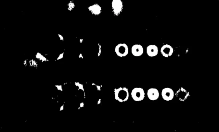
In Fig. 5, we present end-on framing pictures of implosion and equilibrium phases for lling pressure of 3:310
,3 Torr and preionization time of 8 s (one period), where usual m = 0 mode plasma is obtained.
Figure 5. Plasma implosion cross section obtained by IMA-CON framing camera with 0.2 s interval with 3:3 mTorr
Figure 6. Azimuthal rotation of the plasma mode taken from IMACON framing camera with 0.2 s interval
(Hy-drogen, 7:5 mTorr).
In Fig. 6, it starts the appearance of the m = 4 mode. The lling pressure in this case is 7:510
,3Torr and the preionization time is 16 s (two periods).
In Fig. 7, we show the case with same preionization sequence as in Figure 6, but with a Hydrogen lling pressure of 1010
,3 Torr, where the start of framing pictures were delayed by 2 s.
One can notice from the last two framing pictures that during the implosion phase the plasma is circular and it becames more square shaped and rotates around the axis at near maximum compression. After this phase, the plasma rotation is stopped by the leak of particles from the square corners touching the wall, but still mantaining the mode structure. The total time of the sequence of events leading to an square plasma is about 2 s.
Figure 7. Azimuthal rotation of the plasma mode taken from IMACON framing camera with 0.5s interval
(Hydro-gen, 10 mTorr).
The plasma azimuthal rotation inferred from Fig. 7 before the wall touching is 1:410
6rad/s, as obtained from the square plasma rotation during two sequences of frame pictures.
IV. The rotational modes
We use our non resistive MHD model to calcu-late the rotational modes using TC-1 parameters. We solved equation (13) using typical eld reversed equilib-rium magnetic prole, to analyze the m = 2 and m = 4 modes. Taking the magnetic eld at the edge B(rw) to be 3:5 kG, the separatrix radius r0 be 3:5 cm, the peak plasma density n(r0) to be 10
15cm,3, the Alfven transit time A is 0:1 s. Since the measured plasma rotation is 0= 1:4
10
6rad/s, the normalized rotation 0is of the order of 0:2. Estimating the plasma length L to be 20 cm, and considering = 2L, the normalized wavevector kr0 is 0:5. The real and imaginary parts of the eigenfrequency ! = !0=0= !0
A=0 are plot-ted in Fig. 8, for the m=2 mode, as a function of the wavevector kr0showing a decreasing Im(!
0)
A=0and an increasing Re(!0)
A=0, and we dene = Im(!). At kr0
! 0, Fig. 8 shows the Re(!)= = 1 limit , for the rst radial mode, which agrees with the ear-lier work of Freidberg and Wesson [1]. Firstly, we note that Re(!) is dierent from m in the long wavelength and small kr0 limit. This shows a fundamental error in boundary layer analysis which assumes the marginal stability expansion ! = m + i in solving the kr0 limit. The expansion would be adequate in the short wavelength limit. Second, the result of [1] is based on a -pinch with parallel bias where B(r) is nonzero ev-erywhere. They used an incompressible perturbed uid model and assumed a more restricted expansion of the perturbed variables (r~ = 0). In our case we as-sume compressibility and the general expansion of the perturbed quantities obtaining the same general eigen-mode equation as in [4].
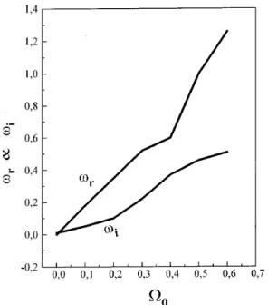
The eigenfrequency !0
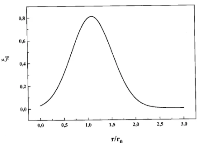
A=0 is plotted as a func-tion of rotafunc-tion 0 in Fig. 9 (0 = 0:20), for the m=2 mode, showing that goes to zero as rotation goes to zero. The displacement r, real and imaginary parts, are plotted in Figs. 10 and 11 respectively as a func-tion of radius r=r0. For the m = 4 mode, Fig. 12 shows the real and imaginary parts of the frequency !0
A=0 as a function of the wavevector kr0. The corresponding displacement r, real and imaginary parts, is shown in Figs. 13 and 14 as a function of radius r=r0: In Figure 15, the eigenfrequency !0
rotation 0 which shows again that
!0 in the zero rotation limit.
Figure 8. Real and imaginary parts of the eigenfrequency
! for m = 2 radial modes as a function of wavevector
kr0(0= 0:20).
Figure 9. Real and imaginary parts of the eigenfrequency
! for m = 2 radial modes as a function of the rotation (kr0= 0:5).
Figure 10. Real part of the eigenfunction r for m=2 as a
function of radius r=r0 (0= 0.20 andkr0 = 0:5)).
Figure 11. Imaginary part of the eigenfunction r for m=2
as a function of radiusr=r0 (0 =0.20 andkr0=0.5).
Figure 12. Real and imaginary parts of the eigenfrequency
! form= 4 radial modes as a function of the wavevector
kr0 (0= 0:20).
Taking 0 = 0:20 for the TC-1 machine, Fig.15 gives Im(!0)
Figure 13. Real part of the eigenfunction rform= 4
(fun-damental mode n = 0) as a function of r (0 = 0:20 and kr0= 0:5).
Figure 14. Imaginary part of the eigenfunction r for m=4
as a function of radiusr=r0 (0=0.20 andkr0 =0.5).
Figure 15. Real and imaginary parts of the eigenfrequency
! form= 4 radial modes as a function of rotation and withkr0 = 0:5.
V. Conclusions
We used a one dimensional MHD model to study the rotational instability in FRC plasmas taking into account the plasma compressibility and comparing our results with the TC-1 machine of Unicamp.
Although the m = 2 mode is commonly observed in many machines, [12], we have only seen the m = 4 mode in TC-1. However, the presence of this mode is compatible with the hybrid code of Harned [6], which has predicted high m modes. We emphasize that the appearance of the m=4 mode in TC-1 depends deci-sively on the timing of the capacitor banks, whereas lling pressure plays a less critical role.
Acknowledgements
This work was supported by the Conselho Nacional de Desenvolvimento Cientco e Tecnologico (CNPq), the Financiadora de Estudos e Projetos (FINEP), and the Fundac~ao de Amparo a Pesquisa do Estado de S~ao Paulo (FAPESP).
References
[1] J. P. Freidberg and J. A. Wesson, Phys. of Fluids13,
1117 (1970).
[2] J. L. Schwarzmeier, D. C. Barnes, D.W. Hewett, C. E. Seyler, A. I. Shestakov and R. L. Spencer, Phys. of Fluids26, 1295 (1983).
[3] D. C. Barnes and D. V. Anderson, Phys. Rev. Letters
46, 1337 (1981).
[4] E. Frieman and M. Rotenberg, Rev. of Mod. Phys.32,
898 (1960)
[5] T. Ishimura, Phys. of Fluids27, 2139 (1984).
[6] D. Harned, Phys. of Fluids26, 1320 (1983)
[7] E. Hameiri, Phys. of Fluids26, 230 (1983).
[8] Y. Ito, M. Tanjyo, S. Ohi, S. Goto and T. Ishimura, Phys. of Fluids30, 168 (1987).
[9] B. Coppi, R. M. O. Galv~ao, R. Pellat, M. Rosenbluth and P. Rutherford, Sov. J. of Plasma Phys. 2, 533
(1976).
[10] R. M. O. Galv~ao and M. A. M. Santiago, Phys. of Flu-ids24, 661 (1981).
[11] D. O. Campos, M. Machida, S. V. Lebedev, M. Kantor, S. A. Moshkalyov and L. A. Berni, Braz. J. Phys.26,
747 (1996).