Abstract
In this paper, the Euler-Bernoulli beam model is used to predict the structural instability of rotating cantilever tubes conveying fluid and subjected to uniform distributed tangential compressive load. The governing equation of motion and boundary conditions of the system are derived using the Hamilton’s principle. Then, Galerkin method is applied in order to transform the resulting equation into a general eigenvalue problem. The present analysis is validated by comparing the results with those available in literature. Further-more, the model is utilized to elucidate the stability characteristics of the system for different conditions.
Keywords
Distributed tangential load; Rotating cantilever; Stability; Flutter.
Effect of Uniformly Distributed Tangential Follower Force
on the Stability of Rotating Cantilever Tube Conveying Fluid
1 INTRODUCTION
The stability analysis of rotating cantilevers has been of interest because of their various applications in mechanical design of the structures. Several research groups have addressed this problem using different experimental, analytical and numerical approaches (Lee, 1994; Sinha et al., 1998; Lesaffre et al., 2007; Fazelzadeh and Hosseini, 2007; Valverde and García-Vallejo, 2009; Kuo et al., 2013). The literature on this topic is vast and is being continuously expanded. In addition, the dynamic stability of cantilever tube subjected to non-conservative forces has been studied for a long time (Simitses and Hodges, 2006; Païdoussis, 2014). The fluid flowing inside the tube acts as the concentrated non-conservative force at the tip of the tube. A follower force is another example of non-non-conservative forces that turns its direction as to always follow the deformation of the structure (Fazelzadeh and KazemiLari, 2013). The stability of the rotating cantilevers, cantilever tubes conveying fluid and cantilever tubes subjected to follower forces has been extensively studied independently of each other. However, very little information has been published on the combined effects of rotation, internal fluid flow and external follower forces.
A. Karimi-Nobandegani S.A. Fazelzadeh * E.Ghavanloo
School of Mechanical Engineering Shiraz University,
Shiraz, 71963-16548, I.R. Iran
http://dx.doi.org/10.1590/1679-78252309
Latin American Journal of Solids and Structures 13 (2016) 365-377
The first study on a rotating cantilever tube conveying fluid has been carried out by Panussis and Dimarogonas (2000). They showed that the rotational motion of the tube has a significant effect on the stability of the system. Nonlinear dynamic analysis of rotating pipe conveying fluid has been studied by Bogdevičius (2003) using finite element method. In another study, the influences of the angular velocity, the velocity of fluid and a tip mass were investigated on the dynamic behavior of a rotating cantilever pipe conveying fluid (Yoon and Son, 2007). The dynamic stability of a rotating cantilever pipe conveying fluid with a crack and tip mass was studied by Son et al., (2010). In addi-tion, few studies have been accomplished to investigate the stability of rotating cantilevers subjected to non-conservative forces (Anderson, 1975; Kar and Neogy, 1989; Kar and Sujata, 1992; Sakar and Sabuncu, 2003; Sabuncu and Evran, 2005; Hosseini and Fazelzadeh, 2011; Fazelzadeh et al., 2014). To the best of our knowledge, only one study (Wang, 2012) has investigated the instability of non-rotating pipes conveying fluid subjected to distributed follower forces.
It should be noted that there is no existing model so far in the literature able to take into account the combined effects of the fluid flowing inside the tube, uniformly distributed tangential follower force and rotation of the tube. For reliable and practical design of these structures, it is necessary to estimate the modal characteristics accurately. Therefore, it is highly desirable to develop and utilize simple and accurate methods. One of the most important practical applications of the current study is in local film-cooling of gas turbine blade which is produced by a row of jets. The other practical application of this work may be used in the design of rotating blades which are under the effect of non-conservative aerodynamic loads.
In this paper, the stability of the rotating cantilever tube conveying fluid and subjected to the distributed follower force is studied. The Euler–Bernoulli beam theory is used as structural model of the cantilever tube. The Hamilton’s principle is utilized to derive the equation of motion and boundary conditions of the system. Using the Galerkin method, the obtained partial differential equation is transformed to ordinary differential equations. The equation of motion is expressed in matrix form and is solved numerically. The influences of the design parameters such as the rotating angular ve-locity, the velocity of fluid flow and magnitude of uniformly distributed tangential follower force are elucidated by the numerical simulation. The results are also compared with those reported in the literature.
2 MATHEMATICAL MODELING
A rotating cantilever tube conveying fluid with length L, and flexural rigidity EIt is attached to a
rigid hub with radius r. The tube is subjected to a distributed compressive tangential load of intensity P (Fig. 1). An internal fluid is assumed to flow steadily through the tube with a constant velocity U. At and Af are the areas of the cross section of the tube and the fluid, respectively, and ρt and ρf their
specific masses, respectively. The masses per unit length of the tube and the fluid are m =ρtAt and
Latin American Journal of Solids and Structures 13 (2016) 365-377 Figure 1: Schematic diagram of a rotating cantilever tube conveying fluid
and subjected to distributed follower force.
The governing differential equation of the system can be obtained from the generalized form of the Hamilton’s principle:
2 2
1 1 0
t t
T cf ncf ncp
t T U W dt t W W dt
(1)where in TT is the kinetic energy of the system, U is the elastic potential energy of the tube, Wcf is
the conservative work due to the fluid flow, and δWncp and δWncf are the non-conservative virtual
work due to the follower force and the fluid flow, respectively. The velocity vector of an arbitrary point on the cantilever due to rotation is given by:
t
r
v Ω r (2)
where r is the position vector of an arbitrary point in the displaced state and Ω is the angular velocity vector. The position vector is defined by:
w
r x z w
x
r i k (3)
in which i and k are the unit vectors along the x- and z-axis, respectively. In addition, w is the lateral displacement. Therefore, the velocity vector of the tube can be obtained:
2
Ω
w w
z r x z w
x t x
v i j k (4)
where (∎) denotes ∂(∎)⁄∂t. The kinetic energy of the tube is
.
1 .
2
t
t t t
V
T
v v dV (5)where dVt is the tube element volume. The relative velocity of fluid flow with respect to the tube is
assumed U, the velocity of fluid have to include the motion of the tube. Therefore, the flow velocity is (Païdoussis, 2014):
f
w U U
x
Latin American Journal of Solids and Structures 13 (2016) 365-377 Substituting Eq. (4) into Eq. (6), we have
2
Ω
f
w w w
U z r x z w U
x t x x
v i j k (7)
Similarly, one can write the kinetic energy of the internal flow as
.1 .
2 f
f f f f f
V
T
v v dV (8)where dVf is the fluid element volume. Therefore, the first variation of the kinetic energy of the
system is simply:
2 2 0 2 0 2 Ω Ω LT f f f f
L
t t t t
T Mw MUw MU w I I w wdx
mw I w d
w
Iw w x
(9)Here (∎ ́) denotes (∂(∎))⁄∂x.
Furthermore, the strain energy of the system is given by:
2 2 2 2 0 1 2 L t w wU EI T x dx
x x
(10)where T(x) denotes total centrifugal force acting at any point x and is given by:
Ω2
2 22
L x T x m r L x
(11)
The work done by the fluid flow is divided into conservative and non-conservative work. The conservative work Wcf due to the fluid flow is (Yoon and Son, 2007):
2 2 0 1 2 L cf w
W MU dx
x
(12)The virtual work δWncf due to the non-conservative component of the fluid flow is as follows:
cnf
W MU w Uw w
x L
(13)
To obtain the virtual work of distributed follower force, one can assume that iand krepresent the corresponding unit vectors in the deformed state of the tube. Therefore, the relationships between the deformed axis of the tube and unreformed state may be written as:
w x
Latin American Journal of Solids and Structures 13 (2016) 365-377 w x
k i k (15)
The total virtual work of non-conservative tangential follower force acting on the cantilever tube might be expressed as:
0
. L
ncp
W P u w dx
i i k (16)Considering small deflections, it can be shown that the longitudinal displacement u(x, t) can also be obtained as:
20 , 1
, 2
x w t
u x t d
(17)Therefore, the eq. (16) can be simplified as
22 0L
ncp
w
W P L x wdx
x
(18)Substituting Eqs. (9), (10), (12), (13) and (18) into Eq. (1), and requiring that the integrand must be zero for any time interval [t1− t2], the governing equation and boundary conditions are obtained.
2 2 2
2 2 2
Ω 2 Ω
Ω 0
2
t t t t f f f f t
mw I I w Mw MUw MU w I I w EI w
L x P L x w
w w
m r L x w
(19)
0 0
0w w
0w L w L (20)
For simplicity of the equation of motion and numerical simulations, the following dimensionless parameters are introduced:
2 3 2 * 2 Ω t tt t f f
t t
E I
x t M M w
u U L w
L L m M M m E I L
I I
M m r P L
L r p
E I L E I M m L
(21)
Substituting Eqs. (21) intoEqs. (19) and (20), one obtains the dimensionless equation of motion and boundary conditions:
4 2 2 2 2 2
2 2
4 2 2 2 2
4 2
2 *
2 2
2 1
1
1 1 0
2
w w w w w w
u u p
Latin American Journal of Solids and Structures 13 (2016) 365-377
0 0 22 1 33 1 0w w w
w
(23)
3 SOLUTION AND STABILITY APPROACH
3.1 Galerkin Method
In order to discretize the partial differential equation, Galerkin method is used. Hence, the following set of modes is assumed to approximate the dynamic behavior of the system:
, i
iw c (24)
where φi(ξ) is function satisfying the boundary conditions and ci(τ) is generalized coordinate.
Consid-ering the boundary conditions of Eq. (23), one can use the following family of the orthogonal functions:
2
1 6 2 1 5 6 2
1 2 1
i
i
i i
i i i i
(25)
Substituting Eq. (24) into Eq. (22), multiplying the resultant equation by φj, and integrating over
the domain [0,1] , the following system of equations can be obtained:
M c
C c
K c
0 (26)where (∎) denotes (∂(∎))⁄∂τ. In addition, [M], [C] and [K] denote the symmetric mass matrix, non- symmetric damping matrix and non-symmetric stiffness matrix, respectively. The matrices can be written as
1 10 0
i j i j
ij
d
dM (27)
10
2 i j
ij u
dC (28)
1 1 1 1
2 2
0 0 0 0
1 2
2 *
0
1
1
1 1
2
i j i j i j i j
ij
j i
d u d p d d
r d
K
(29)
4 STABILITY ANALYSIS
For the stability analysis, it is convenient to rewrite Eq. (26) in the first order variable form as:
q
A q
(30)Latin American Journal of Solids and Structures 13 (2016) 365-377
c q
c (31)
1
10
I A
M K M C (32)
where
I is the unitary matrix. Expressing the state vector as q
qexp
and substituting it into Eq. (30), the standard eigenvalue problem is obtained as below
A I q
0 (33)In order to impose condition of non-trivial solution of the above equation, the determinant of the coefficient matrix must be set to zero as:
0det A I (34)
Expansion of the determinant of above equation provides the system characteristic equation:
, , , ,
0F p u (35)
For given values of η, p, u and β, the eigenvalue λ of the system can be computed numerically from Eq. (35). In general, the eigenvalue λ and the corresponding eigenvector are complex quantities;
λ=Re(λ)+iIm(λ). It should be noted that when p and u are zeros, all of the eigenvalues are pure imaginary conjugates and Re(λ)=0. In the presence of non-conservative parameters, when Re(λ) is positive, the system undergoes unstable oscillations. When Re(λ)=0 and Im(λ)≠0 the system is said
to be in the critical flutter condition.
5 RESULTS AND DISCUSSION
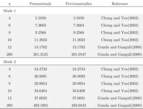
In the following section, a numerical study is carried out to explore the instability characteristics of the rotating cantilever tube conveying fluid subjected to the distributed tangential follower force.Since the effect of hub radius (r*) on the dynamics of rotating cantilever tube conveying fluid has been clearly discussed in previous works (Cheng et al., 2011; Nagaraj andSahu, 1982; Rao and Gupta, 2001; Ozgumus and Kaya, 2007),here we just show how the rotating cantilever tube are influenced by the combined effects of the fluid flowing inside the tube, uniformly distributed tangential follower force and rotation of the tube. In addition, the solution of this problem through the Galerkin method is obtained by seven number of modes. The validity of the model is checked by comparing the obtained results with those given in the literature. Furthermore, the effects of the main parameters including rotating angular velocity, the velocity of fluid flow and magnitude of uniformly distributed tangential follower force on the flutter condition of the tube are also studied.
Latin American Journal of Solids and Structures 13 (2016) 365-377
Yoo (2002), and Gunda and Ganguli (2008) for different rotating angular velocity. It can be seen reasonable agreement.
η Presentstudy Previousstudies Reference
Mode 1
4 5.5850 5.5850 Chung and Yoo(2002)
6 7.3603 7.3604 Chung and Yoo(2002)
8 9.2568 9.2568 Chung and Yoo(2002)
10 11.2023 11.2023 Chung and Yoo(2002)
12 13.1702 13.1702 Gunda and Ganguli(2008)
200 201.3125 201.0547 Gunda and Ganguli(2008)
Mode 2
4 24.2733 24.2734 Chung and Yoo(2002)
6 26.8091 26.8092 Chung and Yoo(2002)
8 29.9954 29.9954 Chung and Yoo(2002)
10 33.6404 33.6409 Chung and Yoo(2002)
12 37.6032 37.6031 Gunda and Ganguli(2008)
200 493.1985 492.6843 Gunda and Ganguli(2008)
Table 1: Comparison of non-dimensional natural frequencies of a rotating cantilever for different non-dimensional rotation speeds ΩL2 m EI/ .
In addition, Fig. 2 shows the coalescing trend of the imaginary parts of eigenvalues related to the first two coupled-modes of the system in the absence of rotating speed and fluid flow effects. The results are found to be in good agreement with given results by Simitses and Hodges (2006). Moreover, the validity of the present formulation is proved through the good correlation between the results obtained in this study for the stability of an unloaded cantilever tube conveying fluid and the corre-sponding calculated results by Païdoussi(2014). The numerical results for dimensionless velocity (uf)and frequency (ωf) corresponding to instability and restabilization conditions as a function of β
are given in Fig. 3. Good agreement is observed between the two results.
The effect of non-dimensional rotating angular velocity on the critical flow velocity and corre-sponding flutter frequency of the cantilever tube conveying fluid in the absence of the follower force is shown in Fig. 4. In this figure, the results are computed for five non-dimensional rotating velocities. It is recognized that the uf and ωfcurves contain a set of S-shaped segments. It is well known that
these segments are associated with the instability-restabilization-instability sequences of tube’s vibra-tion. It should be noted that the negative-slope portions of the curves correspond to the thresholds of restabilization [Païdoussis, 2014]. It is also clear that the slopes of these segments are different for various values of rotating velocity. It is seen that the general dynamics of the system with η> 0 is similar to that for η=0, but for η> 0 the additional restoring force due to centrifugal effect causes uf
Latin American Journal of Solids and Structures 13 (2016) 365-377
0 5 10 15 20
0 5 10 15 20 25 30 35 40 45 50
Im
(λ
)
p
Present Study
Simitses and Hodges [2006]
Figure 2: Comparison between the results obtained in the present model against those presented by Simitses and Hodges [2006].
Fig. 5 presents the dimensionless critical fluid flow velocity and corresponding flutter frequency of non-rotating cantilevered tube conveying fluid as a function of β for five different non-dimensional values of the follower force. It is seen that the S-shaped curves in the stability diagram has a point of transition. In other words, for β< 0.22, p stabilizes the system and for β> 0.22, p destabilizes the system. Moreover, it is observed that as the follower force increases, the value of flutter frequency of the system is decreased.
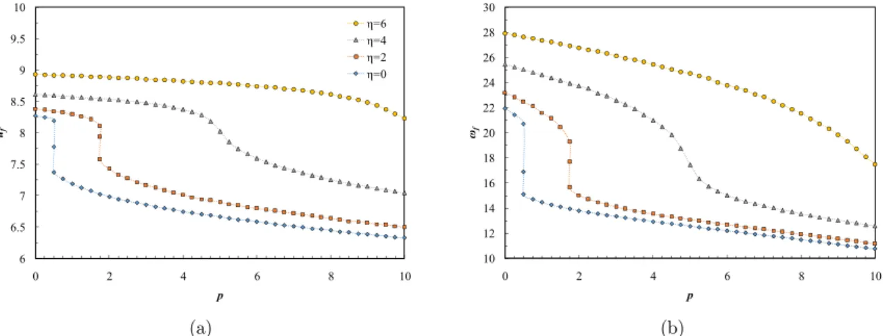
Finally, we consider the stability of rotating cantilever tube conveying fluid subjected to uniformly distributed tangential follower force. Figs. 6 and 7 show the variations of the critical fluid flow velocity and flutter frequency of the system as a function of follower force for different values of rotating angular velocity for β=0.3 and β=0.8, respectively. It is observed that the curves contain a set of segments with positive and negative slopes. It is well known that these segments are associated with the instability-restabilization-instability sequences of tube’s vibration. It should be noted that the positive-slope portions of the curves correspond to the thresholds of restabilization.
3 5 7 9 11 13 15 17
0 0.2 0.4 0.6 0.8 1
uf
β
Paidoussis [2014] Present study
10 20 30 40 50
0 0.2 0.4 0.6
ωf
β
Latin American Journal of Solids and Structures 13 (2016) 365-377
4 8 12 16 20 24
0 0.2 0.4 0.6 0.8 1
uf
β
η=20 η=15 η=10
η=5 η=0
(a)
0 20 40 60 80 100 120 140
0 0.2 0.4 0.6 0.8 1
ωf
β
(b)
Figure 4: Variation of critical values as a function of β for varying η (a) critical flow velocity, and (b) flutter frequency.
It is clear that the slopes of these segments are different for different values of the non-dimensional angular velocity. The non-dimensional angular velocity parameter has a stabilizing effect on the tube’s vibrational characteristics. In the segments with negative slope and for a given value of follower force, it can be observed that as the non-dimensional rotating angular velocity is increased, the critical fluid flow velocity of the tube increases and conversely, in the segments with positive slope, as the non-dimensional rotating angular velocity is increased, the critical fluid flow velocity of the tube decreases. These figures can be used for determining the load limits when designing the cantilevers in which combined loads may be applied.
3 6 9 12 15 18
0 0.1 0.2 0.3 0.4 0.5 0.6 0.7 0.8 0.9 1
uf
β
p=20 p=15 p=10 p=5 p=0
(a)
0 10 20 30 40 50 60 70 80
0 0.1 0.2 0.3 0.4 0.5 0.6 0.7 0.8 0.9 1
ωf
β
(b)
Latin American Journal of Solids and Structures 13 (2016) 365-377
6 6.5 7 7.5 8 8.5 9 9.5 10
0 2 4 6 8 10
uf
p
η=6 η=4 η=2 η=0
(a)
10 12 14 16 18 20 22 24 26 28 30
0 2 4 6 8 10
ωf
p
(b)
Figure 6: Variation of critical values as a function of p for varying η and β = 0.3 (a) critical flow velocity, and (b) flutter frequency.
9 9.5 10 10.5 11 11.5 12 12.5 13 13.5 14
0 2 4 6 8 10 12 14 16
uf
p
η=6 η=4 η=2 η=0
(a)
15 20 25 30 35 40 45 50
0 2 4 6 8 10 12 14 16
ωf
p
(b)
Figure 7: Variation of critical values as a function of p for varying η and β = 0.8 (a) critical flow velocity, and (b) flutter frequency.
6 CONCLUSIONS
The stability behavior of the rotating cantilever tubes conveying fluid and subjected to a distributed tangential load was investigated. In spite of some achievements in the stability analysis of the rotating cantilevers, to the authors’ knowledge, there has been no attempt to tackle the problem described in the present investigation. Considering the rotation of the cantilever and including the coupled effect of the internal fluid flow and the distributed tangential load are the main contributions of the present paper. In addition, the validity of the results was successfully verified through comparison with data available in the literature.
A detailed parametric study of the proposed model revealed the following points:
Latin American Journal of Solids and Structures 13 (2016) 365-377
(b) It was indicated that the effect of distributed tangential load was to decrease the critical flow velocity corresponding to the flutter condition.
(c) For a given non-dimensional angular velocity, higher values of the β yield higher critical non-dimensional frequency of lateral vibrations.
References
Anderson, G.L. (1975). Stability of a to dissipative, rotating cantilever subjected aerodynamic, and transverse follower forces. Journal of Sound and Vibration 39(1): 55-76.
Cheng, Y., Yu, Z., Wu, X., Yuan, Y. (2011). Vibration analysis of a cracked rotating tapered beam using the p-version finite element method. Finite Elements in Analysis and Design, 47(7), 825-834.
Fazelzadeh, S.A. and Hosseini, M. (2007). Aerothermoelastic behavior of supersonic rotating thin-walled beams made of functionally graded materials. Journal of Fluids and Structures 23: 1251–1264.
Fazelzadeh, S.A. and KazemiLari, M. A. (2013). Stability analysis of partially loaded Leipholz column carrying a lumped mass and resting on elastic foundation. Journal of Sound and Vibration 332: 595-607.
Fazelzadeh, S.A., Marzocca, P., Hosseini, M. (2014). Fluid-Thermoelastic Behaviors of FGM Thin-Walled Beams and Pipes. Encyclopedia of Thermal Stresses. Springer Netherlands: 1700-1711.
Hosseini, M. and Fazelzadeh, S.A. (2011). Thermomechanical stability analysis of functionally graded thin-walled cantilever pipe with flowing fluid subjected to axial load. International Journal of Structural Stability and Dynamics 11: 513-534.
Kar, R.C. and Neogy, S. (1989). Stability of a rotating, pre-twisted, non-uniform cantilever beam with tip mass and thermal gradient subjected to a non-conservative force. Computers & Structures 33: 499-507.
Kar, R. C. and Sujata, T. (1992). Stability boundaries of a rotating cantilever beam with end mass under a transverse follower excitation. Journal of Sound and Vibration 154: 81-93.
Kuo, C.F.J., Tu, H.M., Huy, V.Q. and Liu, C. H. (2013). Dynamic stability analysis and vibration control of a rotating elastic beam connected with an end mass. International Journal of Structural Stability and Dynamics. 13: 1250066 Lee, H. P. (1994). Effect of gravity on the stability of a rotating cantilever beam in a vertical plane. Computers & Structures 53: 351-355.
Lesaffre, N., Sinou, J.J. and Thouverez, F. (2007). Stability analysis of rotating beams rubbing on an elastic circular structure. Journal of Sound and Vibration 299: 1005-1032.
Nagaraj, V. T., andSahu, N. (1982). Torsional vibrations of non-uniform rotating blades with attachment flexibility. Journal of Sound and Vibration, 80(3), 401-411.
Ozgumus, O. O., and Kaya, M. O. (2007). Energy expressions and free vibration analysis of a rotating double tapered Timoshenko beam featuring bending–torsion coupling. International journal of engineering science, 45(2), 562-586. Paidoussis M.P. (2014) Fluid-Structure Interactions (Academic press, New York).
Panussis, D.A. and Dimarogonas, A.D: (2000). Linear in-plane lateral vibrations of a horizontally rotating fluid-tube cantilever. Journal of Fluids and Structures 14:1-24.
Sabuncu, M. and Evran. K. (2005). Dynamic stability of a rotating asymmetric cross-section Timoshenko beam sub-jected to an axial periodic force. Finite Elements in Analysis and Design 41: 1011-1026.
Rao, S. S., and Gupta, R. S. (2001). Finite element vibration analysis of rotating Timoshenko beams. Journal of Sound and Vibration, 242(1), 103-124.
Latin American Journal of Solids and Structures 13 (2016) 365-377
Sinha, S. C., Marghitu, D.B. and Boghiu. D. (1998). Stability and control of a parametrically excited rotating beam. Journal of Dynamic Systems, Measurement, and Control 120:462-470.
Simitses, G.J. and Hodges, D.H. (2006) Fundamentals of Structural Stability (Elsevier, Oxford).
Son, I.S., Yoon, H.I., Lee, S.P. and Kim, D.J. (2010). Effects of tip mass on stability of rotating cantilever pipe conveying fluid with crack. International Journal of Modern Physics B 24(15-16): 2609-2614.
Valverde, J. and García-Vallejo, D. (2009). Stability analysis of a substructured model of the rotating beam. Nonlinear Dynamics 55:355-372.
Wang, L. (2012). Flutter instability of supported pipes conveying fluid subjected to distributed follower forces. Ac-taMechanicaSolidaSinica 25:46-52.
![Figure 2: Comparison between the results obtained in the present model against those presented by Simitses and Hodges [2006]](https://thumb-eu.123doks.com/thumbv2/123dok_br/18886813.424023/9.808.216.547.93.311/figure-comparison-results-obtained-present-presented-simitses-hodges.webp)