Abstract
An experimental investigation was performed on stainless steel hemispherical shells under axial compression. Eight kinds of shells with radius-to-thickness ratios that range from 57.1 to 125 were designed and manufactured for this study. The shells were com-pressed to more than 50% of their radii by a solid flat plate. To avoid contact between the base plate and the deformed central part of the shells, most of the shells were placed on a plate with a hole in the center. Nonetheless, one type of shell was placed on a solid base plate without a hole to analyze the effect of the base plate. As per an observation of collapse modes and load-deformation shell relations, the load-deformation process of a hemi-spherical shell that is compressed by a flat plate can be divided into four stages: local flattening (Stage I), axi-symmetric inward dimpling (Stage II), non-symmetric multiple lobes (Stage III), and peripheral deformation and buckling stage (Stage IV). The present study mainly studies Stage IV, which can be categorized into peripheral compression (Stage A), peripheral buckling (Stage B), buckling expanding (Stage C), and overall collapse (Stage D).
Keywords
Hemispherical shell, quasi-static compression, deformation behav-ior, central dimpling, peripheral buckling
Peripheral Deformation and Buckling of Stainless Steel
Hemispherical Shells Compressed by a Flat Plate
1 INTRODUCTION
Thin shell structures, especially spherical shells, are widely used in various engineering fields, e.g., aviation, navigation, machinery, chemical industry, and construction because of the light weight, wide span, material-saving capability, high load-carrying capacity, diverse appearance, and excellent membrane effect of such structures. The study of the collapse behavior of thin shell structures has received considerable attention from researchers in the past four decades, and spherical shell struc-tures have been studied experimentally and analytically under both quasi-static and dynamic load-ings in axial directions.
Huiwei Yang a Jianxing Hu a Le Xu a Guoyun Lu b, c
a Shanxi Key Lab of Material Strength &
Structural Impact, Taiyuan University of Technology, 030024 Taiyuan, China [email protected]
[email protected] [email protected]
b College of Architecture and Civil
Engi-neering, Taiyuan University of Technology, 030024 Taiyuan, China
c State Key Laboratory for Strength and
Vibration of Mechanical Structures, Xi’an Jiaotong University, 710049 Xi’an, China [email protected]
http://dx.doi.org/10.1590/1679-78252434
Latin American Journal of Solids and Structures 13 (2016) 257-271
Linearly elastic spherical shells that were subjected to contact loading by rigid plates were first examined by Updike and Kalnms (1970). These researchers determined that when a shell is treated as linearly elastic, it is initially deformed, as reflected in the flat contact region against the rigid plate (Stage I). Then, the shell buckles with an axi-symmetric dimple within a ring of contact load-ing at the first bifurcation point (Stage II). Finally, the shell may buckle into a non-symmetric shape at a second bifurcation point (Stage III). The collapse behavior of a rigid, perfectly plastic spherical shell was also studied by Updike (1972). The predicted analysis results were restricted to the overall displacements between a few thicknesses and approximately one-tenth of the shell radius (Stage II). Moreover, an extensive theoretical and experimental investigation was made into this problem by Kitching et al. (1975). Deformation patterns that are symmetric and non-symmetric about the axis were also studied analytically and experimentally for spherical shells with radius-to-thickness (R/t) ratios that range between 36 and 460. De Oliveira and Wierzbicki (1982) investigat-ed the deformation of hemispherical shells under concentratinvestigat-ed point loads, as well as that between two rigid plates. Moreover, the researchers assumed the formation of two plastic hinges. Calladine (1986) proposed a solution to the axial concentrated compression of shells. In this solution, com-sion was several times greater than the wall thickness but was significantly smaller than the radius. Many researchers studied the deformation and structure response of spherical shells with differ-ent radii/thicknesses. Hemispherical shells with R/t ranging between 8 and 32 were subject to an analysis and quasi-static testing by Kinkead et al. (1994). These researchers assumed that defor-mations occur in two phases without undergoing the multiple lobes stage. Experiments were per-formed on aluminum hemispherical shells with R/t ranging between 15 and 240 by Gupta et al. (1999). A simple analytical model was also developed to predict load-compression and energy-compression curves for metallic spherical shells according to the concepts of stationary and rolling plastic hinges (SPH & RPH). Simulation experiments were conducted on hemispherical shells by Gupta et al. (2008), along with analysis and quasi-static testing. The behavior of plastic hinges was analyzed during the progressive buckling of spherical shells through three-dimensional numerical simulations. Furthermore, Gupta N.K. and Gupta P.K. (2009) studied the effects of the geometrical parameters of shells (wall thickness t, radius R, height Z, and R/t ratio) and the friction between shell-platen interfaces on the energy-absorbing capacity of shells using finite element method. In addition, Gupta N.K. and Gupta P.K. (2014) investigated the different collapse modes of metallic hemispherical shells that are resting on a flat plate and are compressed with axial central point load and offset load. Shariati and Allahbakhsh (2010) studied the buckling of steel hemispherical shells under various loadings. Karagiozova et al. (2013) experimentally and numerically investigated the deformation and snap-through behavior of a thin-walled elastic spherical shell in the form of a table tennis ball subjected to axial compression under quasi-static and impact loading. In this study, the researchers estimated the influence of dynamic effects on the compression process. Knochea and Kierfeld (2014) used two different models to examine classical axi-symmetric buckling. One model is based on classical nonlinear shell theory and the other is an approximate analytical model that was proposed by Pogorelov (1967). Knochea and Kierfeld also explained the secondary buckling transi-tion, in which a dimple loses its axi-symmetry, according to continuum elasticity theory.
Latin American Journal of Solids and Structures 13 (2016) 257-271
The complete collapse process was obtained and detailed through observation, especially in the sit-uation in which compression displacement exceeds half the shell radius. Thus, a new collapse mode is proposed. The influence of radius and thickness on the collapse mode is discussed as well.
2 EXPERIMENTS
Hemispherical shells with different thicknesses and radii were made of stainless steels. These shells were compressed between two flat plates on a universal testing SUMSCMT 5105A machine. Fur-thermore, eight group specimens were designed and manufactured for this study. A large displace-ment that exceeds the half-radius was loaded on these specimens to investigate structural response. The load-deformation curves of each specimen were measured in the tests. The deformation modes of the specimens were observed and captured at different displacements by a camera. The speci-mens and the quasi-static testing system are detailed in the following sections.
2.1 Specimens
All of the experiments described in this paper are performed on hemispherical shells stamped by stainless steel plates. Eight group specimens with R/t ratios ranging from 57.1 to 125 were designed and manufactured for this study. To determine the influence of thickness and radius on the defor-mation modes of hemispherical shells, all specimens are prepared with three thicknesses (0.4, 0.5, and 0.7 mm) and three radii (60, 50, and 40 mm), as shown in Table 1.
Specimens Specifications
R (mm) t (mm) R/t D (mm)
R60t0.5 60 0.5 120 40
R60t0.7 60 0.7 85.7 40
R50t0.4 50 0.4 125 35
R50t0.5 50 0.5 100 35
R50t0.7 50 0.7 71.4 35
R40t0.4 40 0.4 100 30
R40t0.5 40 0.5 80 30
R40t0.7 40 0.7 57.1 30
Table 1: Specifications of specimens: R – Radius of shells; t – thickness of shells; R/t – radius-to-thickness ratio of shells; D – displacement of top plate.
2.2 Experimental Set-up
Latin American Journal of Solids and Structures 13 (2016) 257-271 Figure 1: Schematic of the experimental device.
Specimens were compressed exceeding 50% of their radii with a crosshead speed of 2 mm/min to observe the entire collapse process of the hemispherical shells, especially the collapse mode of hemispherical shells with considerably large deformation. The detailed maximum loading displace-ment for each specimen is listed in Table 1.
The central part of the shell dimples and then moves toward the other side of the base plate through the hole at the center when the hemispherical shell was compressed. This loading state is called the inversion-loading state. For comparison, a solid plate was designed without a hole at the center to investigate the influence of the contact between the internal surface of the dimpling part and the base plate on the deformation mode of the hemispherical shell. During this loading process, the central part of the shell does not move toward the other side of base plate but instead comes into contact with this area. The shell then dimples again, thus resulting in bottom out. Therefore, the loading method is labelled as the bottom out loading state.
3 EXPERIMENTAL RESULTS
The final deformation modes of all specimens and load-deformation curves are presented in the fol-lowing sections, along with the corresponding inner and peripheral profiles of hemispherical shells at different stages. Furthermore, the typical load- deformation curves, the number of lobes formed, and the deformed shapes at different stages of compression were captured and presented.
3.1 Final Deformation Modes
Latin American Journal of Solids and Structures 13 (2016) 257-271
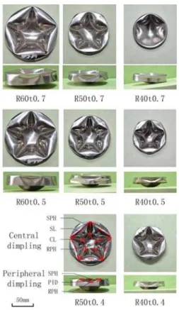
The central deformation of most shells display six lobes, that is, five side lobes (SL) and one central lobe (CL), as displayed in Fig. 2. The SL is a conical surface that is surrounded by two straight SPHs and two curved RPHs. The CL consists of five curved RPHs. The special specimen R40t0.7 displays a mode between the six lobes and a circle. A small R/t shell has high carrying capacity, thus significantly complicating the formation of multiple lobes in shells. In this study, no other multiple lobes mode is observed; however, thin-walled hemispherical shells display different multiple lobe modes with different thicknesses or radii, as per the studies conducted by Kinching (1975) and Gupta (2008). Shells with high R/t values collapse into five to eight lobe deformations, and all lobes are not initiated at the same time. These deformations are maximized with the pro-gress of compression, according to Gupta (2008).
Peripheral deformation can be divided into non-symmetric (diamond) and axi-symmetric ring modes in light of the deformation presented in Fig. 2. Most shells deform into multiple inward dimples outside the SPHs located between two neighboring SLs. This deformation is localized. This mode is called the diamond mode because it is similar to the diamond-buckling mode of cylindrical shells (Singace and El-Sobky, 2001). Peripheral dimples display semi-elliptical shapes and consist of a straight plastic hinge and a curved plastic hinge. The peripheral buckling of specimen R40t0.7 exhibits axi-symmetric folding be-cause the buckling shape is an approximate axi-symmetric ring. This is the axi-symmetric ring mode, which is similar to the axi-symmetric buckling mode of cylindrical shells (Singace and El-Sobky, 2001). Thus, the peripheral buckling mode is affected by the central inward dimpling mode.
Latin American Journal of Solids and Structures 13 (2016) 257-271
3.2 Deformation Process
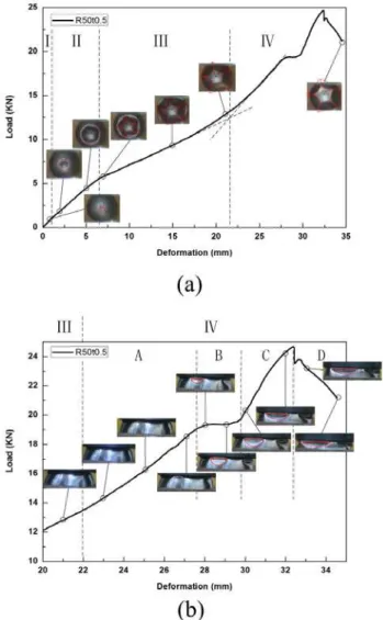
The deformation modes of shells of different R/t values with compression were observed and rec-orded by cameras. Moreover, the deformation curves were obtained as well. The load-deformation curves of all specimens display a similar trend; hence, a representative specimen (R50t0.5) was used in analyzing the detailed deformation process of a hemispherical shell. Fig. 3(a) shows the deformation modes at different stages, as well as the load-deformation curve of the shell. The first point of note is the significant increase in the slope of the load in the latter period of com-pression. Therefore, four stages of deformation were defined during the compression of a typical hemispherical shell as follows: Stage I, Stage II, Stage III, and Stage IV. The different stages can be distinguished clearly from the load-deformation curve, as indicated in Fig. 3(a).
Latin American Journal of Solids and Structures 13 (2016) 257-271
Stage I: Local flattening (0–1 mm). In the initial stage of compression, the hemispherical shell de-forms with a flat contact region against the rigid plate. In this stage, loading displacement is less than shell thickness.
Stage II: Axi-symmetric inward dimpling (1–6.5 mm). With the progress of deformation, the hemi-spherical shell undergoes axi-symmetric inward dimpling inside a ring of contact with the top rigid plate. The axi-symmetric dimple expands and moves the RPH at the point of contact away from the axis of the shell, along with the plate.
Stage III: Non-symmetric multiple lobes (6.5–22 mm). With an increase in compression, the collapse mechanism involves buckling with a non-symmetric shape. This mechanism involves five lobes and a central region. SPHs are formed between the consecutive lobes. In this stage, the RPH is in pentagonal mode and the dimpling shape maintains six lobes; the inward dimpling region alone expands due to the radial outward movement of the RPH. In this stage, deformation is initiated at an early stage of compression and occurs over a wide range of compression.
Stage IV: Peripheral deformation and buckling (22 mm–). When compression exceeds almost 22 mm, the RPH stops moving, and the radius of the central shell remains constant. Mean-while, the slope of the load-deformation curve increases sharply. Then, the shell periphery buckles, thus reducing load. This buckling occurs beyond the SPHs and between two neighboring SLs. Finally, the shell boundary slips with a decrease in load.
The first three stages have been studied by many researchers, but the fourth stage has not been mentioned in previous papers. Therefore, the current study focuses on the deformation process, as well as the influence of radius and thickness on Stage IV. Fig. 3(b) shows the peripheral defor-mation process of specimen R50t0.5 with compression. According to the slope of load-defordefor-mation curve and observations of the peripheral deformation process, Stage IV can be divided into four detailed stages, namely, peripheral compression (Stage A), peripheral buckling (Stage B), buckling expansion (Stage C), and overall collapse (Stage D).
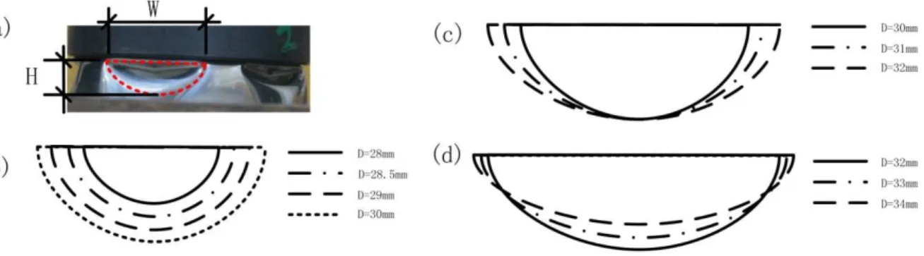
The schematic of peripheral dimple evolution at the different stages of Stage IV is shown in Fig. 4. By combining Figs. 3(b) and 4, we can detail the evolution of peripheral deformation in Stage IV.
Latin American Journal of Solids and Structures 13 (2016) 257-271
When compression deformation exceeds 22 mm, the slope of the load-deformation curve increas-es sharply and the shell is strengthened. The periphery outside the central dimpling region is com-pressed, and no other deformation occurs. This stage is called Stage A, which involves peripheral compression. In this stage, no peripheral dimple is formed but the RPH almost stops moving.
With the progress of compression, the region outside the SPHs between the two neighboring SLs experiences local inward dimpling, as indicated in Fig. 3(b). Load stops increasing as a result of peripheral local buckling. This stage is called Stage B, which involves peripheral buckling. This stage is the process of forming multiple peripheral inward dimples that are semi-elliptical shape, correspond to multiple lobes, and expands toward the boundary with compression. Stage B is illus-trated in Fig. 4(b). The height and width of the peripheral dimple increase with the progress of compression in this stage.
Peripheral inward dimples are formed quickly, and their height is maximized. The inward dim-ple expands, thereby moving the curved RPH toward both sides as shown in Fig. 4(c). This expan-sion results in a second strengthening of the load-deformation curve because the movement of the curved RPH needs additional energy. This stage is called Stage C, which involves buckling expan-sion. In this stage, the width of the peripheral dimple increases with compression while the height is maintained.
With an increase in compression, two initial peripheral dimples intersect and a new dimple is formed under this intersection region, as displayed in Fig. 3(b). The load-carrying capacity of the shell decreases again. Then, the shell boundary slips and overall collapse occurs. This stage is called Stage D, which is the overall collapse stage. In this stage, the width of the initial peripheral dimple increases with compression as height decreases. In the process, a new peripheral dimple forms. The height of the shell periphery is too small to form other dimples. Meanwhile, a second dimple may not always be produced.
In the peripheral deformation and buckling stage, the shell is strengthened before each inward dimpling develops. When the radius of the central dimple approaches the shell radius, the central dimple cannot extend farther from the axe of the shell. As a result of the compression of the loading flat plate, the shell periphery alone is compressed and the central dimple shape does not change. The periphery has a high load-carrying capacity; hence, the first strengthening process occurs. The second strengthening process takes place because the extension of the peripheral dimple dissipates additional energy. Therefore, load must be increased.
Latin American Journal of Solids and Structures 13 (2016) 257-271
4 DISCUSSIONS
The height and width of the peripheral dimple, the length of the SPH, and the radius of central dimple are measured experimentally and are listed in Table 2 to determine the influence of the ge-ometrical parameters of shells on their final collapse shapes. The influence of radius, thickness, and base plate are discussed in consideration of load–deformation curves and final collapse modes.
4.1 Influence of Shell Radius
Specimens with different radii were tested to study the influence of radius on peripheral buckling. The mean slopes of these shells were obtained by averaging the slopes of their load-deformation curves at different stages. The starting point of Stage A was calculated by intersecting the two fit-ting straight lines of Stage III and Stage A.
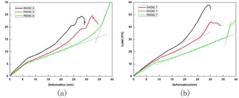
Fig. 5 shows the load-deformation curves for shells with different radii. At constant thickness, shells with small radii supported high loads at the same deformation in all specimens. Shells with a small R/t undergo only Stages A and B. Specimens also display an axi-symmetric ring mode at Stage B, such as in R40t0.7. Fig. 5 also indicates that shells with large radii form multiple lobes early and require little force. Therefore, the centers of shells with large radii buckle easily.
All shells with different radii undergo a load-strengthening stage in the latter period of compres-sion, but the rate of load increase varies. Moreover, the starting point and buckling load of the dif-ferent stages differ for shells with dissimilar radii. The mean slopes, starting points, and buckling loads at the different stages are displayed in Fig. 6.
Fig. 6(a) suggests that the mean slope in Stage A of shells with large radii is larger than that of shells with small radii. In Stage A, the shell periphery alone is compressed, as previously described. Fur-thermore, the periphery of hemispherical shells with large radii exhibits considerable compression stiff-ness. In addition, the starting points of Stage A are higher in shells with large radii than in shells with small radii. Shells with small radii are strengthened earlier than shells with large radii are. Fig. 6(b) indicates how the first buckling point changes with the radius when shell peripheries buckle and load stops increasing. Buckling point is regarded as the maximum deformation in this experiment because the periphery of Specimen R60t0.7 does not buckle. This figure suggests that shells with small radii buckle earlier than shells with larger radii do. Thus, the peripheries of shells with small radii buckle easily.
Latin American Journal of Solids and Structures 13 (2016) 257-271
Figure 6: (a) Mean slope and starting point of Stage A and (b) buckling point to shell radius.
For Specimen R60t0.5, the peripheral shell buckled but load did not decrease because the center of the shell touched the base plate as a result of high deformation. In the process, shell resistance increases. For Specimen R60t0.7, the peripheral shell buckles and load decreases because high thickness prevents the center of the shell from touching the base plate at similar deformations. Although the centers of shells with large radii buckle easily, the peripheries of shells with large radii exhibit high resistance such that these peripheries do not buckle as easily as in shells with small radii.
4.2 Influence of Thicknesses
Specimens with different thicknesses were also tested to determine the influence of thickness on peripheral buckling. Load-deformation curves were obtained. Furthermore, the dimensions of central and peripheral dimples were measured.
Fig. 7 depicts load-deformation curves of shells with different thicknesses. At a constant radius, all specimens with thick shells exhibit a high carrying capacity in the overall process. For shells with a constant radius, thin shells formed multiple lobes early and supported low force. The centers of thin shells buckle easily.
Latin American Journal of Solids and Structures 13 (2016) 257-271
Fig. 8 shows (a) the mean slope and starting point of Stage A and (b) the buckling point to shell radius. As per the combination of Figs. 7 and 8(a), the mean slope and starting point in Stage A vary for shells with different thicknesses. The mean slope in Stage A is higher given thick shells than given thin shells. The periphery of a thin shell has low resistance. In addition, the starting point in Stage A of thick shells is higher than in thin shells. Thin shells begin to buckle earlier than thick shells; that is, thin shells tend to shift from central to peripheral deformation. Fig.8 (b) de-picts critical compression displacement when shell periphery first buckles and the load stops increas-ing. This figure suggests that 0.5-mm thick shells buckle the earliest.
Figure 8:(a) Mean slope and starting point of Stage A and (b) buckling point to shell radius.
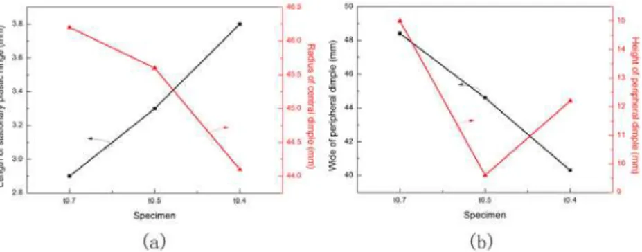
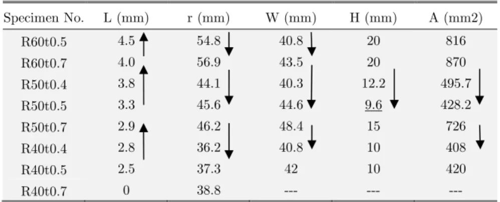
The dimensions of central and peripheral dimples, including the length of SPHs, the radii of central dimples, the width and height of the peripheral dimple, and the approximate area of the peripheral dimple, which is defined as W × H, are measured and listed in Table 2. Fig. 9 exhibits the geometry of the central dimple and the peripheral dimples of shells with different thicknesses.
Fig. 9(a) and Table 2 indicate that the mean length of SPHs increases with a decrease in shell thickness. However, the radius of the central dimple shrinks. Given the same deformation, thin shells form large SLs and small CLs. This finding may be attributed to the low bending stiffness of thin shells. Thus, the radius of the plastic hinge is smaller than in other thick shells. Thin shells possess a wide unformed periphery and delay periphery buckling such that the peripheries of thin shells do not buckle quickly.
Latin American Journal of Solids and Structures 13 (2016) 257-271
Specimen No. L (mm) r (mm) W (mm) H (mm) A (mm2)
R60t0.5 4.5 54.8 40.8 20 816
R60t0.7 4.0 56.9 43.5 20 870
R50t0.4 3.8 44.1 40.3 12.2 495.7
R50t0.5 3.3 45.6 44.6 9.6 428.2
R50t0.7 2.9 46.2 48.4 15 726
R40t0.4 2.8 36.2 40.8 10 408
R40t0.5 2.5 37.3 42 10 420
R40t0.7 0 38.8 --- --- ---
Table 2: Experimental results: L – Length of SPH; r – Radius of the central dimple; W – width of the peripheral dimple; H – height of the peripheral dimple; A – approximate area of the peripheral dimple, which is defined as W × H.
Fig. 9(b) shows that the width of peripheral dimples increases with thickness. Moreover, the pe-ripheral dimples of thick shells are tall. Nonetheless, Specimen R50t0.5 exhibits a short pepe-ripheral dimple and contradicts the above trend because of the formation of a second dimple. The area of peripheral dimples increases with shell thickness because thin shells exhibit a wide peripheral region (given that the central dimples of thin shells have a small radius) and low bending stiffness. These factors lead to local buckling in the periphery of shell.
At similar deformation, thick shells have high resistance and stability and do not buckle easily not only at the center but also at the periphery. However, the central dimples of such shells are large in terms of area, whereas their peripheral dimples are small.
4.3 Influence of Base Plates
In this study, specimens were placed on a rigid plate with a hole in the center. This loading mode is called inversion state and was designed to prevent contact between the central deformed shell and the base plate. However, hemispherical shells are often affected by the base plate in practice. A solid base plate without a hole in the center was used to determine the effect of the base plate. This loading mode is defined as the bottom out loading state. The collapse modes and load-deformation curves of shells in inversion and bottom out loading states are compared in Fig. 10.
Latin American Journal of Solids and Structures 13 (2016) 257-271 Figure 10: Collapse mode and load-deformation curves of R50t0.7 on a solid base plate (bottom out loading state)
and on a plate with a hole (inversion state): SPH – stationary plastic hinge; SL – side lobe; CL – central lobe; RPH – rolling plastic hinge; PID – peripheral inward dimple; OP – outside pentagon;
MP – mid-pentagon; IP – inside pentagon; PH – plastic hinge.
The final modes differ in inversion state and bottom out loading state. The central dimple of the shell consists of multiple lobes in inversion state. In this state, the lobes display conical surfaces that consist of two straight SPHs and two curved RPHs. However, the central dimple in the bottom out loading state is a triple pentagonal mode. In this mode, the inner pentagon is developed by a second dimpling of the shell apex after bottoming out. The middle pentagon is the RPHs of the central dimples, and the outer pentagon is formed by peripheral buckling. The RPHs of all shells in the inversion loading state are curved, but those in bottom out loading mode are almost straight. By contrast, the peripheral dimples of all shells in inversion loading state are semi-elliptical. Howev-er, the dimples in bottom out loading mode are trapezoidal and are composed of three plastic hinges, as well as the boundary. The degree of collapse of the shells in bottom out loading state is higher than that of shells in the inversion loading state.
5 CONCLUSIONS
Experiments were conducted on the deformation behavior of stainless steel hemispherical shells compressed between two plates in this study. The following results were obtained:
(1) The collapse modes of shells under high deformation (greater than 50% of the shell radius) are mainly divided into two parts: one is the central deformation of shells, and the other is the peripheral deformation. The central deformation of shells displays multiple lobes or an axi-symmetric mode. Peripheral deformation can be divided into non-symmetric (dia-mond) mode and axi-symmetric ring mode under the influence of central collapse mode. (2) On the basis of experimental observations and the slope of load-deformation curves, the
non-Latin American Journal of Solids and Structures 13 (2016) 257-271
symmetric multiple lobes (Stage III), and peripheral deformation and buckling stage (Stage IV). Stage IV can be divided further into peripheral compression (Stage A), pe-ripheral buckling (Stage B), buckling expansion (Stage C), and overall collapse (Stage D). (3) As the radius of shells increases, central load carrying capacity decreases. However,
pe-ripheral resistance is enhanced.
(4) As the wall thickness of shells increases, both central load carrying capacity and peripher-al resistance increase as well.
(5) Base plates exert a significant stiffening effect in Stage IV, but not on the first three stag-es. The central dimple of shells in inversion loading state is a conical surface with multiple lobes while the dimple in bottom out loading state is a triple pentagon. By contrast, the peripheral dimples of shells in inversion loading state are semi-elliptical while the dimple in bottom out loading state is trapezoidal.
Acknowledgments
This project is sponsored by The National Nature Science Fund of China (No. 11372209) and Research Project Sup-ported by Shanxi Scholarship Council of China (2013-044).
References
Calladine, C.R. (1986). Analysis of large plastic deformation in shell structures. In:Bevilacqua, L., Feijoo, R., Valid, R. (Eds.), Inelastic Behaviour of Plates and Shells. IUTAM Symposium. Springer, Berlin, pp. 69-101.
De Oliveira, J.G., Wierzbicki, T., (1982). Crushing analysis of rotationally symmetric plastic shells. Journal of Strain Analysis, 17(4): 229-236.
Gupta, N.K., Eswara Prasad, G.L., Gupta, S.K., (1999). Axial compression of metallic hemispherical shells between rigid plates. Thin Walled Struct, 34 (1): 21-41.
Gupta, P.K., Gupta, N.K., (2009). A study of axial compression of metallic hemi-spherical domes. Journal of Materi-als Processing Technology, 209(4): 2175-2179.
Gupta, N.K., Mohamed Sheriff, N., Velmurugan, R., (2008). Experimental and theoretical studies on buckling of thin hemispherical shells under axial loads. Int J Mechanical Sciences, 50(3): 422-432.
Gupta, P.K., Gupta, N.K., (2014). A study of different modes of collapse in metallic hemispherical shells resting on flat plate and compressed with hemispherical nosed indenter, Int J SolidS Struct, 51(13): 2518-2528.
Karagiozova, D., Zhang, X.W., Yu, T.X., (2012). Static and dynamic snap-through behaviour of an elastic hemi-spherical shell. Acta Mech. Sin., 28 (3): 695–710.
Kinkead, A.N., Jennings, A., Newell, J., Leinster, J.C., (1994). Hemispherical shells in inelastic collision with a rigid wall tentative analysis and recent quasi static testing. Journal of Strain Analysis, 29 (1): 17-41.
Kitching, R., Houston, R., Johnson, W., (1975). A theoretical and experimental study of hemi hemispherical shells subjected to axial loads between flat plates. International Journal of Mechanical Sciences, 17(11): 693-703.
Pogorelov, A.V., (1967). Geometrical method in nonlinear of elastic shells. Moscow: Izd, Nauka.
Knochea, S. and Kierfeld, J., (2014). The secondary buckling transition: Wrinkling of buckled hemispherical shells. The European Physical Journal E., 37(7):1-21.
Latin American Journal of Solids and Structures 13 (2016) 257-271 Singace, A. A., El-Sobky, H., (2001). Uniaxial crushing of constrained tubes. Proceedings of the Institution of Me-chanical Engineers, Part C: Journal of MeMe-chanical Engineering Science, 215(3): 353-364.
Updike, D. P., Kalnins, A., (1970), Axisymmetric behavior of an elastic spherical shell compressed between rigid plates, Journal of Applied Mechanics, 37(3), 635-640.