Numerical Modeling of High-Speed Free Bulging of Thin-Wall
Aluminum Tubes under the Action of Impulse Electromagnetic
Forces
PASCA Sorin
1, PASCA Alexandra
21
University of Oradea, Romania,
Department of Electrical Engineering, Faculty of Electrical Engineering and Information Technology, Universitatii St. No. 1, 410087 Oradea, Romania, E-mail: [email protected]
2
Technical University of Cluj-Napoca, Romania, Faculty of Electrical Engineering,
G. Baritiu St. No. 26, 400027 Cluj-Napoca, Romania, E-mail: [email protected]
Abstract – The paper proposes an approach in numerical modeling of electromagnetic forming of aluminum tubes. The investigated technology refers to a free expansion/bulging, without a die, of a thin wall aluminum tube. The aim is to build an accurate model that can take into account the particularities of the process, which is useful for numerical investigations regarding an optimal design of the device.
Keywords: electromagnetic forming, finite element analysis, multiphysics, numerical models.
I. INTRODUCTION
It is well known that electromagnetic forming (EMF) is efficiently applied to thin-wall workpieces made by metals with high electrical conductivity, e.g. copper, aluminum or aluminum alloys. Even if EMF is known as principle from decades, only in recent years this technology became again attractive. The growing interest comes mainly from top industrial branches, such as automotive or aerospace industry [1,2,3]. For example, some automotive fabricants are trying to expand the use of aluminum alloys for the automotive parts in order to reduce the weight of vehicles and improve the fuel efficiency.
However, there are, unfortunately, some drawbacks in processing aluminum alloys using conventional technologies, in relatively slow forming processes, such as large springback and low formability. Previous years researches [4,5,6,7,8] prove that these shortcomings can be overcome when high-speed forming processes, like hydroforming or magnetoforming, are used. As a consequence, a detailed analysis of the high-speed forming process and an optimal design of the device are compulsory and an accurate numerical model is an essential tool in this purpose.
After previous works [9,10,11,12] related mainly to EMF applied to thin metal sheets, this paper deals with the numerical model associated to free bulging of thin-wall aluminum tubes, taking into account that the
electromagnetic and structural phenomena are coupled, i.e. influence each other.
II. THE ELECTROMAGNETIC FORMING FACILITY Generally, the main components of the EMF facility are: the capacitor bank, the charging circuit, the discharging circuit and the technological device. The charging circuit has a rectifier as a power source and a switch that offer the possibility to cut-off the charging. The discharging circuit is represented by a spark-gap as a switch and special shielded cables that fed the technological device. The device for the free bulging of thin-wall aluminum tubes consists of an cylindrical rigid coil, made by massive conductor turns, placed symmetrically inside the tube and no die or field concentrator. The capacitor bank is sized to store the total amount of energy needed in the forming process. The tool coil and workpiece are outlined below.
Fig. 1. The forming coil - aluminum tube assembly
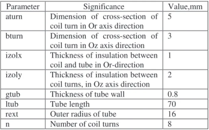
TABLE 1. The geometrical parameters
Parameter Significance Value,mm
aturn Dimension of cross-section of coil turn in Or axis direction
5
bturn Dimension of cross-section of coil turn in Oz axis direction
3
izolx Thickness of insulation between coil and tube in Or-direction
1
izoly Thickness of insulation between coil turns, in Oz axis direction
2
gtub Thickness of tube wall 0.8
ltub Tube length 70
rext Outer radius of tube 16
n Number of coil turns 8
III. ANALYSIS OF ELECTROMAGNETIC FORMING PROCESS
EMF involves a high frequency process, high power and coupled phenomena, in which the electrical and geometric parameters are time dependent. The non-uniform distribution of the current density in conductive regions, respectively the transient skin effect must be considered. In addition, the deformation of the workpiece modifies the magnetic field, which characterizes a strong coupling between electromagnetic and mechanical/structural phenomena [13]. The type of time dependence of source current imposes for EMF process a transient analysis, both for electromagnetic field and for structural analyses.
A. Electromagnetic Field Model
The electromagnetic field phenomena associated to the magnetoforming process are described by the eq. (1):
ex Dt D z z ) r ( r r r J A A
A + =
∂ ∂ ⋅ ∂ ∂ + ⋅ ∂ ∂ ⋅ ∂ ∂
− ν ν σ (1)
The total derivative in (1) has the expression
A A A rot v t Dt D × − ∂ ∂
= , where v is the velocity. In the EMF process, the velocity is non-null only in the workpiece/tube region. [14] shows that the electromagnetic field in a moving, conducting half-space varies from the values obtained in a stationary one but, at a time instant of 100 µs, the differences are only significant if the velocity is of the order of 107 m/s or more. In EMF the process duration is of the order of 100 µs and the velocities are of the order of hundreds m/s, i.e. far below the value for which motion of the half-space becomes significant. Thus, for EMF the electromagnetic field computed in stationary media is a good approximation of the real electromagnetic field in the system. With this assumption, the governing equation expressed in terms of rA can be written:
ex ) r ( t r 1 ) r ( z r z ) r ( r r
r A A ∂ ⋅A =J
∂ + ⋅ ∂ ∂ ⋅ ∂ ∂ + ⋅ ∂ ∂ ⋅ ∂ ∂
− ν ν σ
(2)
The last term in the left part of (2) represents the density of induced currents, non-null in the conductive regions of study domain. This equation is solved using the step by step method in time domain. In EMF process the current density Jex, non-null only in the coil region,
is apriori unknown, its computation requiring at any time step, a second relation between A and Jex, given by
the associated electrical circuit model coupled to the electromagnetic field model. The current that flows through the forming coil is the result of the discharge of the capacitor bank whose capacity C0 and initial voltage
U0 are correlated with the electric parameters of the
assembly coil-workpiece, respectively with the energy necessary for the proper deformation of the metallic tube.
The eight turns of the forming coil (Fig. 1) are considered in the model as solid conductor type and their parameters are computed by the coupling between the electrical circuit and the finite element model B. Mechanical/Structural Model
In terms of mechanical/structural problem, the EMF process is characterized by a large plastic deformation of the workpiece, which occurs in a very short time. The general theory of plasticity is inadequate in this case. A satisfactory approach for this type of material behavior is provided by the theory of rate-dependent plasticity. There are several options for material properties models: Perzyna, Peirce and Anand [15,16].
The material hardening behavior is assumed to be isotropic. The integration of the material constitutive equations are based on a return mapping procedure [16]. Both stress and material tangential stiffness matrix are consistent at the end of time step. A typical application of this material model is the simulation of material deformation at high strain rate, such as impact.
The Perzyna option has the following form:
m 1
1 0 pl= σ −
σ γ
ε (3)
where σ0 is the static yield stress of the material, σ is the
equivalent stress, γ is the viscosity parameter, m is the strain rate hardening parameter and εpl is the equivalent plastic strain rate. In (3) it can be observed that when γ tends to ∞, or m tends to zero, or εpl tends to zero the solution converges to the static (rate independent) solution
The computation domain of structural problem is limited to aluminum tube region.
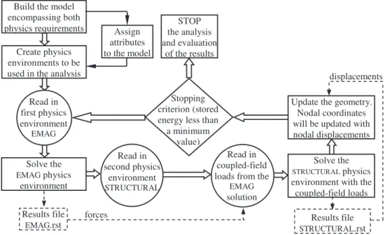
C. The Electromagnetic – Structural Coupling
Fig. 2. Sequentially coupled physics electromagnetic – structural analysis
IV. FINITE ELEMENT MODEL AND RESULTS Based on mathematical models of phenomena described above, and for given values for materials properties and for sources, several numerical simulations using Ansys Multiphysics were performed.
The geometry of computation domain for electromagnetic field is defined by data from Table 1. The capacitor bank has C0 = 200 µF and charging voltage U0 varies between 1 kV and 4 kV, resulting the stored energy between 100 J and 1600 J.
The values for Perzyna model considered for aluminum tube are given in accordance with [15,16,17]. The time step for this full transient analysis was considered between 0.1 and 1 µs.
The computation domain for electromagnetic field and mesh details are illustrated in Fig. 3. Because of deformation/displacement of tube region under the action of electromagnetic forces, at every time step, before starts a new computation in electromagnetics physics, it is necessary to morphing mesh or remeshing the air/insulation region.
a)
Fig. 3. Ansys Multiphysics model of magnetoforming process:
computation domain (a) and mesh details (b)
The variation in time of capacitor voltage and of coil current, for U0 = 3 kV, are presented in Fig. 4, a, b.
Fig. 4. Capacitor voltage (a) and coil current (b) variations b) Results file
STRUCTURAL.rst Create physics
environments to be used in the analysis Build the model encompassing both physics requirements
Read in first physics environment
EMAG
Assign attributes to the model
Solve the STRUCTURAL physics environment with the coupled-field loads Read in
coupled-field loads from the
EMAG solution Stopping
criterion (stored energy less than
a minimum value)
Results file EMAG.rst
Update the geometry. Nodal coordinates will be updated with nodal displacements
forces
displacements STOP
the analysis and evaluation
of the results
Solve the EMAG physics
environment
Read in second physics
environment STRUCTURAL
a)
b)
It can be observed (Fig. 5) that the radial component of the velocity of tube material can exceed 50 m/s at the moment corresponding to maximum of coil current.
Fig. 5. The radial component of velocity in middle point of tube wall
At this moment, magnetic flux density can attain, for a very short time, values above 12 T (Fig. 6).
Fig. 6. Magnetic flux density chart in computation domain
For charging voltage U0=1 kV the radial deformation of tube is insignificant, ∆r = 0.2 mm. A satisfactory deformation, about 8 mm, was obtained for U0=4 kV.
V. CONCLUSIONS
The paper presents an approach in numerical modeling of free bulging by electromagnetic forming of aluminum tubes. The proposed finite element model is based on the sequentially coupling between electromagnetic physics and structural physics, both phenomena being considered transients. The electromagnetic computations also assume the electrical circuit – magnetic field coupling. The characteristics of aluminum tube forming are in accordance with rate dependent plasticity model. Partial results are presented. Some corrections may be made by experimental tests.
Despite the complexity of such numerical model, it can be a very useful tool both for numerical investigation on high speed forming processes, and for optimal design of the device.
REFERENCES
[1] T. Mao and T. Altan, “Aluminum sheet forming for automotive applications. Material properties and design guidelines”, Stamping Journal, pp. 12-15, Jan.-Feb. 2013. [2] W. Lee, D. Kim, J. Kim, K. Chung and S. Hyun Hong,
“Analysis of forming process of automotive aluminum alloys considering formability and springback”, Key Engineering Materials, Trans Tech Publications, Switzerland, vol. 345-346, pp. 857-860, 2007.
[3] The Aluminum Automotive Manual, European Aluminum Assoc., http://www.european-aluminium.eu/aam/, v. 2011. [4] S. Golovashchenko and V. Mamutov “Stress-Strain
Curves of Sheet Material in High-Rate Forming Processes”, 1st Int. Conf. on High Speed Forming, 2004. [5] S. S. Todkar, N. K. Chhapkhane and S. R. Todkar
“Investigation of Forming Limit Curves of Various Sheet Materials Using Hydraulic Bulge Testing with Analytical, Experimental and FEA Techniques”, Int. Journal of Engineering Research and Appl., vol. 3, issue 1, 2013. [6] D. Luca, O. Baltag and S. Damian, “Behavior of the
Aluminum Sheets under Magnetic Impulsive Loading”, Metal ’99, 8th Int. Metallurgical Symposium, Ostrava, vol. 3, p. 54-58, 1999.
[7] M. Sivanandini, S. S. Dhami and B. S. Pabla, “Formability of Magnesium Alloys”, Int. Journal of Modern Engineering Research, vol. 2, issue 4, 2012. [8] P. Verleysen, J. Peirs and L. Duchene, “Determination of
the high strain rate forming properties of steel sheet, Int. Conf. on Comput. Plasticity. Fundam. and Appl., 2011. [9] S. Pasca, T. Vesselenyi, V. Fireteanu, T. Tudorache, M.
Tomse, P. Mudura, E. Vladu and S. Muresan, “Sequentially Coupled Finite Element Model of Transient Magneto-Structural Phenomena in Electromagnetic Forming Processes”, Advanced Topics in Electrical Engg. ATEE 2008, Bucharest, Proceedings, pp. 197-202, 2008. [10]S. Pasca, T. Tudorache and M. Tomse, “Finite Element
Analysis of Coupled Structural and Magneto-Thermal Phenomena in Magnetoforming Processes”, 6th Int. Conf. on Electromagnetic Processing of Materials EPM 2009, Dresden, Germany, Proc., pp. 735-738, 2009. [11]S. Pasca, M. Tomse and E. Vladu, “Finite Element
Analysis of Electromagnetic Forming Process Applied on Thin Wall Metallic Workpieces”, Journal of Electrical and Electronics Engineering, Part I Electrical Engineering, pp. 70-75, No. 2/2009.
[12]S. Pasca and V. Fireteanu, “FE Analysis of Successive Induction Heating and Magnetoforming of Thin Magnetic Steel Sheets”, 14th International Symposium on Numerical Field Calculation in Electrical Engineering IGTE 2010, Graz, Austria, Proceedings CD, 2010.
[13]C. Fluerasu, “Equivalent schemes of electromagnetic forming installations”, Rev. Roum. Sci. Techn., Bucharest, - Serie Electrotechn. et Energ., 16, 4, pp. 593-609, 1971. [14]T. E. Manea, M. D. Verweij and H. Blok, “The
importance of velocity term in the electromagnetic forming process” Proc. of XXVIIth General Assembly of the Int. Union of Radio Science URSI 2002, Maastricht, p. 112– 115, 2002.
[15]S. Kobayashi, Soo-ik Oh and T. Altan, Metal forming and the finite element method, Oxford University Press, 1989. [16]ANSYS Mechanical APDL Theory Reference, 15.0, 2013. [17]P. Klosowski and A. Mleczek, “Parameters’ Identification
of Perzyna and Chaboche Viscoplastic Models for Aluminum Alloy at Temperature of 120 C”, Engineering Transactions, Polish Academy of Sciences, 62, 3, pp. 291-305, 2014.