Tiago José Alves
Marques
Esquemas de Cooperação entre Estações
Base para o LTE no Downlink
Cooperation
Schemes
between
Base
Tiago José Alves
Marques
Esquemas de Cooperação entre Estações Base para
o LTE no Sentido Descendente
Cooperation Schemes between Base Stations for LTE
on the Downlink
Dissertação apresentada à Universidade de Aveiro para cumprimento dos requisitos necessários à obtenção do grau de Mestre em Engenharia Electrónica e Telecomunicações, realizada sob a orientação científica do Prof. Dr. Adão Paulo Soares da Silva, Departamento de Electrónica, Telecomunicações e Informática, Universidade de Aveiro; e do Prof. Dr. Atílio Manuel da Silva Gameiro, Departamento de Electrónica, Telcomunicações e Informática, Universidade de Aveiro.
o júri / the jury
presidente / president Prof. Dr. José Rodrigues Ferreira da Rocha
Professor Catedrático do Departamento de Electrónica, Telecomunicações e Informática da Universidade de Aveiro
orientador / adviser Prof. Dr. Adão Paulo Soares da Silva
Professor Auxiliar do Departamento de Electrónica, Telecomunicações e Informática da Universidade de Aveiro
co-orientador / co-adviser Prof. Dr. Atílio Manuel da Silva Gameiro
Professor Auxiliar do Departamento de Electrónica, Telecomunicações e Informática da Universidade de Aveiro
arguente / examiner Prof. Dr. Paulo Jorge Coelho Marques
agradecimentos / acknowledgements
No momento em que findo o meu percurso académico, é com especial contentamento que agradeço a todas as pessoas que de certo modo me apoiaram ao longo deste curso, e sem os quais nada disto seria possível.
Primeiramente, gostaria de agradecer aos meus pais e restante família, por me permitirem enveredar neste percurso académico, e sempre acreditarem nas minhas capacidades.
À Universidade de Aveiro, principalmente ao Departamento de Engenharia Electrónica e Telecomunicações e ao Instituto de Telecomunicações, por me fornecerem os meios necessários à realização, não só desta dissertação, mas também do curso em si.
Ao Prof. Adão Silva, pela exímia orientação ao longo desta dissertação, pela oportunidade que me concedeu de poder realizar este trabalho e pela transmissão de conhecimentos ao longo deste ano.
A todos os meus amigos e colegas pelo espírito de camaradagem, amizade e entreajuda neste percurso académico.
E finalmente à Cândida, por sempre acreditar em mim e ser a minha maior motivação.
resumo O crescimento exponencial no tráfego de comunicações sem-fios e no número de dispositivos utilizados (smart phones, computadores portáteis, etc.) está a causar um aumento significativo nos níveis de interferência, que prejudicam significativamente os ganhos de capacidade assegurados pelas tecnologias baseadas em ligações ponto-a-ponto MIMO. Deste modo, torna-se cada vez mais necessário que os grandes aperfeiçoamentos na eficiência espectral de sistemas de comunicações sem-fios tenham em consideração a interferência entre células. De forma a tomar em consideração estes aspectos, uma nova arquitectura celular terá de ser desenvolvida. É assim, neste contexto, que surge o LTE-Advanced.
Uma das tecnologias mais promissoras do LTE-Advanced é a Coordenação Multi-Ponto (CoMP), que permite que as estações base cooperem de modo a mitigar a interferência entre células e, deste modo, aumentar a capacidade do sistema. Esta dissertação pretende estudar este conceito, implementando para isso algumas técnicas que se enquadram no conceito do CoMP.
Nesta dissertação iremos considerar a implementação de um sistema de pré-codificação em múltiplas células, em que os pré-codificadores são calculados em cada BS, de modo a mitigar a interferência entre células. São considerados dois pré-codificadores: Distributed Zero Forcing (DZF) e Distributed Virtual Signal-to-Interferance Noise Ratio (DVSINR), recentemente proposto. De seguida o sistema é optimizado com a introdução de algoritmos de alocação de potência entre as sub-portadoras com o objectivo de minimizar a taxa média de erros (BER). Os algoritmos considerados são também avaliados em situações em que a informação do estado do canal é imperfeita. Uma versão quantizada da CSI associada a cada uma das diferentes ligações entre as BS e os UT é assim enviada do UT para a BS. Esta informação é então utilizada para calcular os diferentes pré-codificadores em cada BS. Uma nova versão do pré-codificador DVSINR é proposta de modo a lidar com CSI imperfeito.
Os esquemas propostos foram implementados considerandos especificações do LTE, e os resultados obtidos demonstram que os pré-codificadores removem de uma forma eficiente a interferência, mesmo em situações em que a CSI é imperfeita.
abstract The explosive growth in wireless traffic and in the number of connected devices as smart phones or computers, are causing a dramatic increase in the levels of interference, which significantly degrades the capacity gains promised by the point-to-point multi input, multi output (MIMO) based techniques. Therefore, it is becoming increasingly clear that major new improvements in spectral efficiency of wireless networks will have to entail addressing intercell interference. So, there is a need for a new cellular architecture that can take these factors under consideration. It is in this context that LTE-Advanced arises.
One of the most promising LTE-Advanced technology is Coordinated Multipoint (CoMP), which allows base stations to cooperate among them, in order to mitigate or eliminate the intercell interference and, by doing so, increase the system’s capacity. This thesis intends to study this concept, implementing some schemes that fall under the CoMP concept.
In this thesis we consider a distributed precoded multicell approach, where the precoders are computed locally at each BS to mitigate the intercell interference. Two precoder are considered: distributed zero forcing (DZF) and distributed virtual signal-to-interference noise ratio (DVSINR) recently proposed. Then the system is further optimized by computing a power allocation algorithm over the subcarriers that minimizes the average bit error rate (BER). The considered algorithms are also evaluated under imperfect channel state information. A quantized version of the CSI associated to the different links between the BS and the UT is feedback from the UT to the BS. This information is then employed by the different BSs to perform the precoding design. A new DVSINR precoder explicitly designed under imperfect CSI is proposed.
The proposed schemes were implemented considering the LTE specifications, and the results show that the considered precoders are efficiently to remove the interference even under imperfect CSI.
i
List of Figures ... iii
List of Tables ... v
Acronyms ... vi
1. Introduction ... 1
1.1.
Cellular Communications Evolution ...1
1.2.
Motivation and Objectives...4
1.3.
Structure ...5
2. Multiple Carrier Schemes ... 7
2.1.
Orthogonal Frequency Division Multiplexing ...7
2.1.1.
Orthogonality ...8
2.1.2.
Cyclic Prefix ...8
2.1.3.
Modulation ...10
2.1.4.
OFDM System...10
2.2.
OFDMA ...13
3. Multiple Antenna Techniques ... 15
3.1.
Spatial Multiplexing ...16
3.2.
Diversity ...18
3.2.1.
Receive Diversity ...19
3.2.2.
Transmit Diversity ...20
3.3.
Beamforming...23
4. Long-Term Evolution System ... 25
4.1.
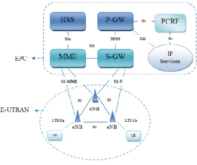
Network Architecture ...27
4.1.1.
User Equipment ...28
4.1.2.
Evolved UMTS Terrestrial Radio Access Network – E-UTRAN ...28
4.1.3.
Evolved Packet Core ...28
4.1.4.
Roaming ...29
4.2.
Physical Layer ...30
4.2.1.
Frame Structure ...30
4.2.2.
Resource Element and Resource Block ...31
ii
5.2.
MIMO Enhancements for LTE-Advanced ...36
5.3.
Relaying and Repeaters ...37
5.4.
Coordinated Multi-Point Transmission – CoMP ...39
5.4.1.
Joint Processing ...41
5.4.2.
Coordinated Beamforming/Coordinated Scheduling ...42
5.4.3.
Clustering ...43
5.4.4.
Backhaul for CoMP ...43
6. Cooperative Schemes Implemented ... 45
6.1.
System Model ...46
6.2.
Distributed Precoder Vectors: DFZ and DVSINR ...48
6.2.1.
Distributed Zero Forcing ...48
6.2.2.
Distributed Virtual SINR (DVSINR) ...49
6.2.3.
Robust DVSINR ...49
6.3.
Power Allocation ...50
6.4.
Quantization...52
6.4.1.
Channel Quantization ...53
6.5.
Channel Coding ...56
6.5.1.
Turbo Coding ...56
6.6.
Numerical Results ...58
7. Conclusions ... 657.1.
Future Work ...66
8. References ... 67iii
Figure 1 - Cellular Systems Evolution ...3
Figure 2 - Subscriptions of Cellular Systems [7] ...3
Figure 3 - Addition of the cyclic prefix to an OFDM symbol...9
Figure 4 - Transmitter and Receiver of an OFDMA system[8] ... 11
Figure 5 - Reference symbols spread over OFDMA subcarriers and symbols ... 11
Figure 6 - OFDM symbol ... 12
Figure 7 - LTE generic frame structure ... 12
Figure 8 - Subcarriers' mapping ... 13
Figure 9 - Multiple Antennas Schemes ... 15
Figure 10 - MU-MIMO Scheme ... 16
Figure 11 - Spatial Multiplexing ... 17
Figure 12 - Reducing fading by using receiver diversity [3]... 19
Figure 13 - Open loop Transmit Diversity ... 21
Figure 14 - Block diagram of the Alamouti Scheme with two transmitter antennas and one receiving antenna ... 22
Figure 15 - Beamforming [14] ... 24
Figure 16 - Diagram of LTE UL selection of modulation scheme [15] ... 25
Figure 17 - Network Architecture [4] ... 27
Figure 18 - EPS Architecture ... 29
Figure 19 - FDD frame structure ... 30
Figure 20 - TDD frame structure ... 31
Figure 21 - Resource Block Structure ... 32
iv
Figure 25 - CoMP cellular System Model [23] ... 40
Figure 26 - System Model Considered ... 46
Figure 27 - Characteristic Function for uniform quantization ... 52
Figure 28 - CIR and frequency response of the channel ... 54
Figure 29 - Frequency Response of the time varying channel ... 54
Figure 30 - CIR of the reconstructed channel ... 54
Figure 31 - Quantized h(τ) ... 55
Figure 32 -MSE of channel quantization in function of clipping value, for several numbers of quantization bits and for LTE extended channel model ... 55
Figure 33 - Structure of the LTE Turbo encoder ... 57
Figure 34 - Block diagram of a transmitter and receiver using Turbo coding[1] ... 57
Figure 35 - Performance evaluation of the distributed precoding schemes for Ntb=4 ... 59
Figure 36 - Performance evaluation of the distributed precoding schemes for Ntb = 6 ... 59
Figure 37 - Performance evaluation of the distributed precoding schemes with power allocation ... 60
Figure 38 - Performance evaluation of the distributed precoder with power allocation with turbo coding ... 61
Figure 39 - Performance evaluation of channel quantization for m=4bits ... 61
Figure 40 - Performance evaluation for channel quantization using m=6 bits ... 62
Figure 41 - Performance evaluation of channel quantization using m=8 bits ... 63
Figure 42 - Performance evaluation of the coded quantized schemes, using m=8 bits ... 63
v
Table 1 - LTEs' system attributes[3] ... 26
Table 2 - Resource Block Configuration ... 32
Table 3 - Physical Channels on LTE ... 33
vi
1G First Generation
2G Second Generation
3G Third Generation
3GPP 3rd Generation Partnership Project
4G Fourth Generation
AES Advanced Encryption Standard
ARQ Automatic Repeat Request
AWGN Additive White Gaussian Noise
BD Block Diagonalization
BER Bit Error Rate
BS Base Station
CAPEX Capital Expendables
CB Coordinated Beamforming
CCs Component Carriers
CDMA Code Division Multiple Access
CIR Channel Impulse Response
CJP Centralized Joint Processing
CM Cubic Metric
CoMP Coordinated Multipoint
CP Cyclic Prefix
CRC Cyclic Redundancy Check
CS Coordinated Scheduling
CSI Channel State Information
CU Central Unit
DFT-S-OFDM Discrete Fourier transform spread OFDM DJP Distributed Joint Processing
DoF Degrees of Freedom
DVSINR Distributed Virtual Signal-to-Interference Noise Ratio
DwPTS Downlink Pilot Timeslot
DZF Distributed Zero Forcing
EAP Extensible Authentication Protocol
EGC Equal Gain Combining
eNB evolved Node-B
EPC Evolved Packet Core
EPS Evolved Packet System
E-UTRAN Evolved UMTS Terrestrial Radio Access Network
vii
GPRS General Packet Radio Service
GSM Global System for Mobile communications
HARQ Hybrid Automatic Repeat Request
HRPD High Rate Packet Data
HSPA High Speed Packet Access
HSS Home Subscriber Server
ICI Inter-Carrier Interference
ICIN Inter-Cell Interference Nulling
IFFT Inverse Fourier Transform
IMS IP Multimedia Subsystem
IMT-2000 International Mobile Telecommunications 2000
IP Internet Protocol
IS-95 Interim Standard 95
ISI Inter-Symbolic Interference
ITU-R International Telecommunication Union - Radiocommunication Sector
JLS Joint Leakage Suppression
JP Joint Processing
JT Joint Transmission
KKT Karush-Kuhn-Tucker
LTE Long-Term Evolution
MAC Media Access Control layer
MIMO Multiple Input Multiple Output
MISO Multiple Input Multiple Output
MME/GW Mobility Management Entity/Gateway
MMSEC Minimum Mean Square Error Combining
MRC Maximum Ratio Combining
MT Mobile Termination
MU-MIMO Multi-user MIMO
OFDM Orthogonal Frequency Division Multiplexing
OFDMA Orthogonal Frequency-Division Multiple Access
OPEX Operational Expendables
PAPR Peak-to-Average Power Ratio
PBCH Physical broadcast channel
PCCC Parallel Concatenated Convolutional Code
PCFICH Physical Control Format Indicator Channel
PCFICH Physical Control Format Indicator Channel
viii
PDSCH Physical Downlink Shared Channel
P-GW PDN gateway
PHICH Physical HARQ Indicator Channel
PHY Physical layer
PJP Partial Joint Processing
PLMN Public Land Mobile Network
PMI Precoding Matrix Indicator
PRACH Physical Random Access Channel
PUCCH Physical Uplink Control Channel
QAM Quadrature Amplitude Modulation
QoS Quality of Service
QPSK Quadrature Phase-Shift Keying
RB Resource Blocks
R-DVSINR Robust-DVSINR
RE Resource Element
RLC Radio Link Control
RN Relay Nodes
RNC Radio Network Controller
SAE System Architecture Evolution
SC Single Carrier
SC-FDMA Single Carrier Frequency Domain Multiple Access
SDMA Space Division Multiple Access
SFBC Space-Frequency Block Coding
S-GW Serving Gateway
SIMO Single Input Multiple Output
SISO Single-input single-output
SLNR Signal-to-Leakage-plus-Noise Ratio
SNR Signal-to-Noise Ratio
SON Self-Organization Network
STBC Space-Time Block Coding
TDD Time Division Duplexing
TDMA Time Division Multiple Access
TD-SCDMA Time Division Synchronous Code Division Multiple Access
TE Terminal Equipment
TFST Time-Frequency Synchronization Transmission
TP Transmission Point
ix
VoIP Voice over Internet Protocol
WCDMA Wideband CDMA
WiMAX Worldwide Interoperability for Microwave Access
ZF Zero Forcing
ZFBF Zero-Forcing Beamforming
1
1. Introduction
1.1. Cellular Communications Evolution
In the past decades, the wireless communications industry has witnessed a tremendous growth, with over six billion wireless subscribers worldwide [1]. The first generation (1G) of cellular communication systems was analog and only supported voice communications with limited roaming. The individual cells were large and the system did not use the available radio spectrum efficiently, so their capacity was very small. The mobile devices were very large and expensive, and had a very restricted users circle.
The second generation (2G) marked the turn of cellular communications to digital systems. This change came with a promise of higher capacity and better voice quality than their analog counterparts. This permitted a more efficient use of the radio spectrum and the introduction of cheaper and smaller mobile devices.
The two widely deployed second generation (2G) systems are the Time Division Multiple Access (TDMA) based GSM (Global System for Mobile communications) and CDMA (Code Division Multiple Access) based Interim Standard 95 (IS-95). These 2G systems were designed to support voice communications, but later on, there were introduced capabilities to support data transmissions. This new systems, called 2.5G, introduced a core network’s packet switched domain and a modified air interface. The General Packet Radio Service (GPRS), a best-effort service that used packet switching data transmissions and could provide data rates from 56 up to 114kbps, incorporated these techniques into GSM. However, data rates of these transmissions were generally lower than that supported by dial-up connections [2].
The ITU-R initiative on IMT-2000 (International Mobile Telecommunications 2000) paved the way to evolution to 3G systems, setting requirements such as a peak data rate of 2Mbits/s and support for vehicular mobility [3]. Both the GSM and CDMA camps formed their own separate 3G partnerships (3GPP and 3GPP2, respectively) to develop IMT-2000 compliant standard, based on CDMA technology. The 3G standard in the 3GPP group is called wideband CDMA (WCDMA) because of its use of a larger 5MHz bandwidth, relatively to a 1.25MHz bandwidth used in 3GPP2’s cdma2000 system.
The world’s dominant 3G system is called Universal Telecommunications System (UMTS) and it encloses the WCDMA system, the most used in the world, as well as Time Division Synchronous Code Division Multiple Access (TD-SCDMA), a derivative of WCDMA, which is also known as the low chip rate option of UMTS TDD (Time Division Duplex) mode [4]. This later is mostly
2
used in China. While WCDMA segregates the base stations’ and mobiles’ transmissions by means of frequency division duplex (FDD), TD-SCDMA uses TDD, and also a smaller carrier of 1.6MHz.
The first release of the 3G standard did not fulfill its promise of high-speed data transmissions as the data rates supported in practice were much lower than that claimed in the standards. In order to enhance the 3G system for efficient data support, 3GPP2 introduced the HRPD (High Rate Packet Data, also called cdma2000-1xEVDO – evolution data only) system, which uses techniques such as channel sensitive scheduling, fast link adaptation and hybrid ARQ, to optimize the data traffic. This system required a separate 1.25MHz carrier and did not support voice traffic. The 3GPP group introduced the HSPA (High Speed Packet Access) enhancement to the WCDMA system. It reused many of the same data-optimized techniques as the HRPD, but it could have both voice and data services in the same 5MHz carrier, by code-multiplexing them. In the later version of HRPD, VoIP (Voice over Internet Protocol) capabilities were introduced to provide both voice and data services on the same carrier.
While HSPA and HRPD were being developed and deployed, IEEE 802 LMSC (LAN/MAN Standard Committee) introduced the IEEE 802.16e standard form mobile broadband wireless access, which has been commercialized under the Worldwide Interoperability for Microwave Access (WiMAX) label by the WiMAX Forum. The mobile version of the standard IEEE 802.16e is referred as Mobile WiMAX and employed a different access technology named OFDMA (Orthogonal Frequency Division Multiple Access) and claimed better data rates and spectral efficiency than that provided by HSPA and HRPD.
The main features of Mobile WiMAX also includes MIMO techniques, scalability from different channels (from 1.25 to 20 MHz), improved security with Extensible Authentication Protocol (EAP) based authentication and Advanced Encryption Standard (AES) based authentication encryption and optimized handover schemes with latencies lower than 50 milliseconds [5].
The introduction of Mobile WiMAX led both 3GPP and 3GPP2 to develop their own version of beyond 3G systems based on the OFDMA technology and network architecture similar to that in Mobile WiMAX. The beyond 3G systems in 3GPP is called evolved universal terrestrial radio access (evolved UTRA) and is also widely referred to as LTE (Long-Term Evolution) while 3GPP2’s version is called UMB (Ultra Mobile Broadband).In November 2008, Qualcomm, UMB’s lead sponsor, announced it was ending development of the technology, favoring LTE instead [6].
Using OFDMA and MIMO based technology, LTE provides peak data rates of 300Mbps in the downlink and 75Mbps in the uplink, as well as QoS provisions that allows the system to transfer with a latency of less than 5ms in the radio access network. It enables the possibility of managing fast-moving mobiles and to support multi-cast and broadcast streams. One of the major changes, compared to its precedents systems, is the introduction of an IP-based network architecture, called Evolved Packet Core (EPC). This network architecture was designed to replace the GPRS core network and supports seamless handovers for both voice and data cell towers, with older technology, such as GSM, UMTS or CDMA2000. LTE will be further discussed in Chapter 4.
3
In the first quarter of 2013 6.5 billion cellular connections were registered, as we can see in the figure bellow. From this, 90% are still GSM – HSPA users, and only 1.4% are from LTE users, but the number is increasing, seen as in the fourth quarter of 2012 only 68 Million users were registered [7].
Figure 2 - Subscriptions of Cellular Systems [7]
2G
3G/IMT-2000
Beyond 3G and 4G/IMT-advanced
GSM
WCDMA/ HSPALTE
LTE-Advanced802.16e/
WiMAX
802.16m
CDMA
Cdma2000 / HRPDUMB
3GPP
IEEE 802 LMSC3GPP2
4
1.2. Motivation and Objectives
4G cellular systems, designated by LTE have recently been deployed, allowing transmission rates way above those seen in 3G systems. However, the increasing demand for higher transmission rate systems cannot be fulfilled by the current cellular architecture. In cellular systems, a way to increase transmission rates is to decrease the cells size, decreasing then the path loss. Nonetheless, considering the current cellular architecture and the unitary frequency reuse, that would lead to a huge increase of users’ interference in the cells edge, leading to a considerable degradation of the systems performance.
In this context it is necessary to develop new cellular architectures that can allow us to reduce or even eliminate interference between the users’ terminals (UTs), mainly at the cell edges. Multicell cooperation or coordination is a promising solution for cellular wireless systems to mitigate intercell interference, improving system fairness and increasing capacity, and thus is already under study in LTE-Advanced under the coordinated multipoint (CoMP) concept.
There are several multicell based approaches depending on the amount of information shared by the base stations (BSs) through the backhaul network and where the processing takes place, i.e., centralized if the processing takes place at the central unit (CU) or distributed if it takes at the different transmitters. Coordinated centralized beamforming approaches, where transmitters exchange both data and channel state information (CSI) for joint signal processing at the CU, promise larger spectral efficiency gains than distributed interference coordination techniques, but typically at the price of larger backhaul requirements and more severe synchronization requirements.
In this thesis we consider a distributed precoded multicell approach, where the precoders are computed locally at each BS to mitigate the intercell interference, assuming only the knowledge of the local CSI (i.e. the channels between a given BS and the cooperative users terminals). Two precoder are considered: distributed zero forcing (DZF) and distributed virtual signal-to-interference noise ratio (DVSINR) recently proposed. Then the system is further optimized by computing a power allocation algorithm over the subcarriers that minimizes the average bit error rate (BER), under per-BS power constraint. Both, upper and lower bounds, used to reduce the search space for the optimum solution and therefore efficiently perform the power allocation procedure, are derived.
The knowledge of CSI at the transmitter is absolutely crucial for the precoded-based systems. However, assuming perfect CSI at the transmitters is not realistic in many practical scenarios and thus in this thesis we also assess the performance of the precoders under imperfect CSI. A quantized version of the CSI associated to the different links between the BS and the UT is feedback from the UT to the BS. This information is then employed by the different BSs to perform the precoding design. A new DVSINR precoder explicitly designed under imperfect CSI is proposed. The considered schemes are implemented and evaluated under the LTE parameters and scenarios.
5
1.3. Structure
After presenting the evolution of wireless communications in the past years and its current status, where LTE is the main 4G standard already deployed in many countries, we present, in Chapter 2 “Multiple Carrier Schemes” and Chapter 3 “Multiple Antenna Techniques” the main enabling technologies of LTE.
Subsequently we present in Chapter 4 “Long Term Evolution System” the major aspects of the LTE system, namely its networks architecture and physical layer. Afterwards, in Chapter 5 “LTE-Advanced” we discuss the evolution of LTE systems, LTE-Advanced and its own enabling technologies. One of the enabling technologies of LTE-Advanced, and the main subject of this study is the concept known as Coordinated Multipoint, also known as CoMP. The main aspects of this concept are presented in a subchapter designated “Coordinated Multi-Point Transmission – CoMP”.
In Chapter 6 “Cooperative Schemes Implemented” we present the cooperative techniques developed in this thesis and evaluate their performance. The system model and the parameters used are defined. The main objective of this chapter is the use of distributed precoder vectors, and further optimization of the same. Also, a simple channel quantization technique is presented and used to evaluate the precoder techniques under imperfect CSI.
Finally, in Chapter 7 we conclude the work made throughout this thesis and provide some guidelines for future.
7
2. Multiple Carrier Schemes
Single Carrier (SC) transmission schemes modulate the information in only a carrier, adjusting the carriers phase or amplitude (or sometimes both). The higher the data rate, the higher the symbol rate in a digital system and thus the required bandwidth is higher [8].
Using medium access techniques based on frequency multiplexing – Frequency Division Multiple Access (FDMA), different users use different carrier frequencies to access simultaneously the communication system [8]. The biggest emphasis in the development of this type of system is on the mitigation of excessive interference between carriers, seeing that the transmitted signals are not sinusoidal. This suggests that if the channel is under-spread (the coherence time is bigger than the delay spread), it is then approximately invariant in time for a big enough time scale [9]. The use of such type of systems requires the usage of guard bands, which may render the system inefficient.
The solution for this interference, caused by the guard band requirements, passes by the selection of the system parameters that allow us to attain orthogonality between the different transistors, thus creating sub-carriers that don’t interfere with each other, but whose spectrums may overlap in the frequency domain.
2.1. Orthogonal Frequency Division Multiplexing
The basic concept of OFDM (Orthogonal Frequency Division Multiplexing) is to divide the available spectrum in parallel narrowband channels, denominated by subcarriers, and sending information in this parallel channels, at a low transmission rate [3]. By doing so, each channel experiences flat-fading which leads to only some of the OFDM subcarriers being affected by the fades and thus, instead of losing the entire symbol, we just lose portions of the symbol and its recovery may be possible by using proper coding and error correction, simplifying a lot the frequency equalization. Although the frequency response of the several channels overlaps, they are orthogonal to each other, since the frequencies of the different subcarriers are chosen so that, in the frequency domain, the neighbor subcarriers have zero values for the sampling times of the required subcarrier. In an OFDM system with sub-carriers there will be transmitted NC data symbols in parallel, each modulated in a different sub-carrier. Hence, the duration of an OFDM symbol is given by:
(2.1.1)
8
(2.1.2)
where stands for the sub-carrier spacing, given by:
(2.1.3)
Each carrier is modulated by a data symbol. An OFDM symbol is formed simply by the addition of the different modulated signals from the sub-carriers.
The OFDM system relays on digital technology, using the Fast Fourier Transform (FFT) and Inverse Fourier Transform (IFFT) to move the signal between the time and frequency domain, without the loss of information, assuming that the classical requirements for digital signal processing in terms of minimum sampling rates and word lengths are fulfilled [8].
2.1.1. Orthogonality
As stated previously, in order for a receiver to separate the overlapped subcarriers without interference, said subcarriers must be orthogonal to each other. The property of orthogonality allows simultaneous transmission of additional subcarriers in a tight frequency space without interference from each other, thus being the main advantage of OFDM.
The definition of orthogonality is stated in the following equation:
∫
( )
( ) {
(2.1.4)
In other words, what this equation represents is that if we have two different functions and multiply and integrate them, over a symbol period, the result is null if the functions are orthogonal to each other.The most basic form of modulation applied to the subcarriers is square wave phase modulation, which produces a frequency spectrum represent by a ( ) function [4], that is characterized by having a maximum amplitude at the center and null amplitude in multiples of , where T is the duration of the modulated symbol. What makes OFDM a practical transmission system is that we can match the subcarrier modulation rate to the subcarrier spacing such that the nulls in the spectrum of one subcarrier line up with the peaks of the adjacent subcarriers.
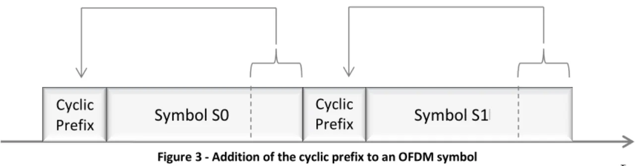
2.1.2. Cyclic Prefix
The orthogonality of the OFDM sub-carriers can be lost when the signal passes through a time dispersive channel, due to inter-symbolic interference, seeing that the symbol do not confine to their time slots, spreading over the next slots. Nevertheless, a cyclic extension of the OFDM signal can be made so to avoid interference [10].
9
The cyclic prefix is a guard time, bigger than the maximum time delay of the different radio channel paths. The last part of the sequence is replicated in the guard time, on the beginning of the OFDM symbol. The addition of this prefix makes the transmitted OFDM symbol periodic, and helps avoid inter-symbolic interference, since all the samples in the slot ( to ) undergo the same
type of interference. The periodic nature of the signal also allows for a discrete Fourier spectrum, enabling the use of DFT and IDFT in the receiver and transmitter respectively. [8]
Within each OFDM symbol the guard period added increases the length of the symbol waveform, being the total length given by:
(2.1.5)
where is the length of the guard period and the useful symbol time corresponding to the size of the IFFT that generated the OFDM signal. The figure bellow shows the structure of the OFDM symbol.
The length of the Cyclic Prefix is chosen regarding a compromise between the increase of energy transmitted due to the increase of the CP length, thus causing a loss in the SNR, and having its length corresponding at least to the offset between the slowest and fastest subcarrier to make the received subcarrier unaffected by any dispersion to avoid both ISI and ICI.
Despite this method benefits in terms of limitation of inter-symbolic interference, the utilization of a cyclic prefix implies a certain loss of spectral efficiency, since it reduces the transmission rate.
The loss of SNR caused by the insertion of the CP, depicted previously, is described in equation (2.1.6).
(
)
(
(2.1.6)
The duration of the short and long cyclic prefix for the LTE is 4.7µs and 16.7µs respectively [10]. The OFDM symbol period is of , so according to equations (2.1.5) and (2.1.6), weCyclic
Prefix
Symbol S0
Cyclic
Prefix
Symbol S1
t
10
get that for the short CP is of 1.0708 and 1.25 for the long CP. In terms of spectral
efficiency, given by , the short CP has a spectral efficiency of 93.4% and the long 80%.
2.1.3. Modulation
The basic principle of multicarrier modulation is to divide the available bandwidth, , into a number sub-bands, or subcarriers. Each one of this subcarriers has a width of . So, instead of transmitting the data stream in a serial way, at a baud rate of , a multicarrier modulation scheme splits the data symbols into blocks of data symbols, which are then transmitted in parallel, by modulating the subcarriers. The duration of a multicarrier scheme symbol is then given by .
When we add more subcarriers the symbol period increases and, therefore, the data stream becomes more robust to channel distortion, impulse noise and fading. Those channel effects could result in inter-symbolic interference (ISI) when the time dispersion becomes significant, compared to the symbol period.
2.1.4. OFDM System
An OFDM system uses the properties of the OFDM concept presented previously in order to enable that multiple users can access the shared medium.
The concept of such approach is that the symbols to be transmitted from one BS towards multiple UT are modulated in the frequency domain, mapped to different sub-carriers and then an IDFT is used to generate a time domain signal. A cyclic prefix, as described previously, is inserted before each orthogonal frequency division multiplex (OFDM) symbol, in order to assure that even a channel with large delay spread does not cause ISI, and that a transmission leads to a circularly symmetric convolution of the transmitted samples with the channel. Each receiving UE can then discard the cyclic prefix, perform a DFT, and obtain (scaled and noisy) transmitted symbols in the frequency domain again.
In LTE the subcarrier spacing is with a cyclic prefix (CP) duration of
(short/long CP) [10], regardless of the total available bandwidth. Since the
subcarriers are orthogonal to each other when the sampling is done, the other subcarriers will have zero value.
The transmitter of an OFDMA system uses IFFT blocks to create the signal. Each input for the IFFT block corresponds to the input representing a particular subcarrier and can be modulated independently of the other subcarriers. This is followed by a Cyclic Extension, whose purpose was explained previously. The cyclic prefix makes the OFDM symbol periodic, allowing a Fourier spectrum, which enables the use of IFFT at the transmitter and FFT at the receiver.
11
Figure 4 - Transmitter and Receiver of an OFDMA system [8]
At the receiver the cyclic prefix must be removed. Although this guard interval protects the symbol against ISI, each subcarrier may be affected by different amplitude and phase changes, due to the channel impact. In order to account this kind of effects, pilot symbols are added, with proper placement in both time and frequency domain, to the OFDM symbol. These pilot symbols are known references that form a time and frequency domain grid, which facilitate the channel estimation, so that the receiver can interpolate the effects of the channel to the different subcarriers. An example of said grid is presented in the figure bellow
.
A typical type of receiver solution is the frequency domain equalization, which basically reverts the channel impact for each subcarrier. In OFDMA this means to simply multiplying each subcarrier (with the complex valued multiplication) based on the estimated channel frequency response (the phase and amplitude adjustment each subcarrier has experienced) of the channel [8].
12
One last assignment that the OFDM receiver must accomplish is time and frequency synchronization, which allows the correct frame and OFDM symbol timing to be obtained so that the correct part of the received signal is dropped. While time synchronization is achieved by the correlation between the known data samples (typically the pilot symbols) and the actual received data, for frequency synchronization the frequency offset between the transmitter and the receiver is estimated by using an estimation of the frequency offset between the UT and the BS, where the UT locks to the frequency obtained from the BS.
A time and frequency representation of an OFDM symbol is presented below.
Figure 6 - OFDM symbol
Figure 7 - LTE generic frame structure
(𝑛, 𝑖)
𝑓
𝑁𝐶 𝐵𝑂𝐹𝐷𝑀 𝑁𝐶 𝑓 0 0 𝑁𝑂𝐹𝐷𝑀𝑛
Time Fr equ enc ies Su b carr iers 0 𝑁𝐶 𝑇𝑂𝐹𝐷𝑀 𝑇𝑓𝑟 𝑁𝑂𝐹𝐷𝑀𝑇𝑂𝐹𝐷𝑀′ Cyclic Prefix #0 #1 #2 #3 … #19 1 Frame = 10 ms (Radio Frame) 1 Slot = 0.5ms 1 Sub-Frame = 1ms = TTI 0 1 2 3 4 5 613
2.2. OFDMA
Orthogonal Frequency-Division Multiple Access (OFDMA) is a multi-user version of the digital modulation scheme stated previously, OFDM. It distributes different sets of subcarriers, allocated in continuous groups or distributed, to different users at the same time.
The usage of an OFDMA system in mobile communications came from the fact that the transmissions, occurring in a shared medium, susceptible to rich scattering, needed a simple and flexible access for a high number of communication entities. There was a need for a low-cost and efficient signal processing solution that can divide a mobile communications system into a large number of flexible bit pipes, according to the many users’ needs. The standard for mobile communications, LTE, uses an OFDMA approach to deal with the matters stated previously.
One of the OFDMA features is the capacity of mapping subcarriers in two different matters, in continuous groups or in a distributed manner. We can see in the figure bellow the difference between this two types of subcarrier mapping. By using the later we are able to exploit multiuser diversity.
Figure 8 - Subcarriers' mapping
2.2.1. Advantages
While being computationally inexpensive and sacrificing only a reasonable extent of capacity for the cyclic prefix, OFDMA has the advantage of being easily designed to fulfill different spectral masks through an appropriate choice of guard bands, it is able to avoid ISI and inter-carrier-wise equalization at the receiver side and is highly suitable for multiple access.
N-Point IFFT N-Point IFFT .. . .. . f
Localized subcarriers Distributed subcarriers
User 1 User 2 .. . .. . User K User 1 ... f ... ... ...
14
2.2.2. Disadvantages
The OFDMA system may present some disadvantages, being the most relevant one that of a high peak-to-average power ratio (PAPR), due to the performance of modulation on the frequency domain and the application of an IDFT. In the uplink, this aspect may be critical as it implies that a large power amplifier (PA) back-off is needed, leading to a faster depletion of handset battery. To cope with this problem, 3GPP decided to employ single carrier frequency domain multiple access (SC-FDMA) in the uplink, where modulation is performed in the time domain, after which a small DFT is applied and the signals are mapped to the sub-carriers to be used by the terminal before the actual large IDFT.
15
3. Multiple Antenna Techniques
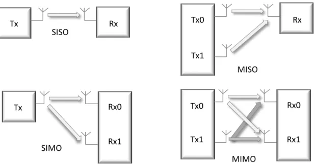
Multiple antenna techniques allow base stations and mobile equipment’s to use multiple antennas in radio transmissions and receptions, in order to increase data rates and performance, or reduce ISI and interference from other users. There are three main multiple antenna techniques, which have different objectives and are implemented in different ways.
One of the most used techniques is diversity processing, which increases the received signal power and reduces the amount of fading by using multiple antennas at the transmitter, the receiver, or both. In spatial multiplexing, also known as MIMO (Multiple Input Multiple Output), the transmitter and receiver both use multiple antennas in order to increase the systems data rates. Lastly, beamforming uses multiple antennas at the base station in order to separate the users that share the same resources; this can be seen as a multiple access technique referred as space division multiple access (SDMA).
There are three multi-antenna configurations, which allow exploiting both diversity and spatial multiplexing, depending on the number of antennas in both the transmitter and the receiver, MISO (Multiple Input Multiple Output), SIMO (Single Input Multiple Output) and MIMO (Multiple Input Multiple Output). The figure bellow illustrates these different schemes. The SISO system is also added to comparison.
Tx
Rx
SISO
Tx0
Rx
MISO
Tx1
Rx0
SIMO
Tx
Rx1
Rx0
MIMO
Tx0
Rx1
Tx1
16
Single-input output (SISO) is the well-known, typical wireless configuration, single-input multiple-output (SIMO) is the configuration where a single transmitting antenna and multiple receiving antennas ( ) are used, multiple-input single-output (MISO) has multiple ( ) transmitting antennas and one receiving antenna and MIMO has multiple ( ) transmitting and receiving ( ) antennas.
Multiple antenna configurations can also be used to separate the users that share the same resources, being usually called as multiuser MIMO (MU-MIMO), which refers to a configuration that comprises a base station with multiple transmit/receive antennas interacting with multiple users, each equipped with single or multiple antennas. This scheme is depicted in the figure bellow.
3.1. Spatial Multiplexing
Spatial multiplexing is often described as the use of MIMO antennas. This name is derived from the inputs and outputs to the air interface, so that multiple inputs refer to the transmitter and multiple outputs to the receiver. So, if the transmitter and the receiver both have multiple antennas, then we can set up multiple parallel data streams between them, in order to increase the data rate.
Spatial multiplexing offers a linear increase in the transmission rate (or capacity) for the same bandwidth and with no additional power expenses, by splitting the bit stream into two half-rate bit streams, modulated and transmitted simultaneously from both antennas. The receiver, having knowledge of the channel, recovers these individual bit streams and combines them so as to recover the original bit stream. In a system with transmit antennas and receive antennas, often known as a spatial multiplexing system, the peak data rate is proportional to ( , ) [11].
This concept can be extended to MU-MIMO. In such a case, two users can transmit simultaneously their respective information to the base station equipped with two antennas. The base station can then separate the two signals and, likewise, transmit two signals with spatial filtering so that each user can decode its own signal correctly. By doing so, we can increase the system’s capacity proportionally to the number of antennas at the base station and the number of users.
Tx/Rx
Tx/Rx Tx/Rx
17
.
.
.
Ant. 1 Ant. 𝑀𝑟 𝑛 𝑛𝑀𝑟 Equalization G 𝑥 𝑥𝑀𝑡 𝑥2.
.
.
Ant. 1 Ant. 2 Ant. 𝑀𝑡 Precoding w𝑠
𝐇
𝑀𝑟 𝑀𝑡𝑠
Let us consider the system model represented in the following figure, assuming that the CSI is available at the transmitter:
In matrix notation, what we can see in the figure is represented by:
(3.1.1)
where is the sent signals vector, with size , is the received
signal vector, with size ,
[
] , , , , , , (3.1.2)
is the MIMO channel matrix, with size ; ( , 2 ) represents the noise vector. The MIMO channel can be converted into a set of parallel channels. This can be done by decomposing the matrix, using the singular value decomposition (SVD), as
(3.1.3)
where and are unitary matrices of size and ( ( ) ( , )) and is a diagonal matrix whose elements are non-negative real numbers,
[
] (3.1.4)
Setting the precoding matrix, as,
2 (3.1.5)
with size , where is a square diagonal power allocation matrix of size
18
[]
2
(3.1.6)
The equalizer matrix is set as,
(3.1.7)
So, the transmitted signal over the antennas is given by,
(3.1.8)
where is the data vector of size . Replacing and on the
received signal we get
2 (3.1.9)
The estimated transmitted data symbols can then be obtained as,
2 (3.1.10)
2 ̃ (3.1.11)
The soft estimate of the th data symbol is,
√ ̃, , , (3.1.12)
As we can see, the estimated data symbol is free of interference, being only affected by noise. So, converting MIMO channels into parallel channels through SVD allows us to transmit parallel, interference free, data symbols.
3.2. Diversity
Diversity means that the same information can be sent over different independent paths, and can be obtained in time, frequency and space. The main idea behind the diversity concept is to send the same information bits through different fading paths and then combine the information received over these paths in the receiver, in order to mitigate the fading effects.
Time diversity consists of sending the same information in different time periods, separated by time intervals bigger than the coherence time. In general, with very short transmission time of 1ms subframe in the LTE system, there is not much time-diversity available (except for the case of
19
very high UT speeds) [3]. The biggest setback of time diversity is the fact that it diminishes the data rates, due to its data repetition.
On the other hand, frequency diversity enables the transmission of the same narrow-band signal in different carriers, separated by a coherence bandwidth. In LTE systems, it can be exploited by scheduling transmissions over distributed resources. However this type of diversity requires the use of more bandwidth.
3.2.1. Receive Diversity
Receive diversity is most often used in the uplink, where the base stations use multiple antennas to pick up more copies of the received signal. The signals that reach the receiver antennas have different phase shifts, but they can be removed by antenna-specific channel estimation. The base station can then add the signals together in phase, without risking destructive interference between them.
Figure 12 - Reducing fading by using receiver diversity [3]
Both signals, due to the existence of obstacles between the transmitting and the receiving antennas, are subject of fading. The effects of that fading will generate different paths for the transmitted data, which are received with temporal variations of amplitude and phase. If the two individual signals undergo fades at the same time, then the power of the combined signal will be low. But if the antennas are far enough apart (a few wavelengths of the carrier frequency), [2] then the two sets of fading geometries will be very different, so the signals will be far more likely to undergo fades at completely different times. Thus, we have reduced the amount of fading in the combined signal, which in turns reduces the error rate.
It is usual for base stations to have more than one receive antenna. In LTE, the mobile’s test specifications assume that the mobile uses two receive antennas [12], so the systems are expected to use receive diversity on both downlink and uplink. A mobile’s antennas are closer together than
20
those of a base station, so the benefits of receive diversity are reduced, but the situation can often be improved using antennas that measure two independent polarizations of the incoming signal.
A list, of the most common receive diversity schemes, is presented below:
Selection Combining – The receiver selects the antenna with the highest received
signal and ignores the signal received from the other antennas.
Switched Combining – The receiver sets a SNR threshold and if the received signal
at a determined antenna is above that value, than it is selected until it drops again under that threshold.
It is also very common to use frequency equalizers, and the most used are presented below:
Equal Gain Combining – the received signals from the multiple receiving antennas
are summed up coherently, compensating the phase rotation caused by the channel.
Maximum Ratio Combining – the received signals from the different antennas are
weighted individually depending on the reliability of the signal in each antenna and then the phase distortion is compensated by calculating the complex conjugate of the frequency response of the channel. Afterwards the signals are aligned and combined.
Zero Forcing Combining – designed for each data symbol in order to remove the
interference, by restoring the orthogonality between users inverting the channel frequency response. However, this equalizer boosts the noise when the frequency response of the channel is in deep fading.
Minimum Mean Square Error Combining – it minimizes the mean square error
between the transmitted and estimated signal. It is a trade-off between noise enhancement and interference removal. For high SNR, this equalizer tends to the ZF.
3.2.2. Transmit Diversity
Transmit diversity reduces the amount of fading by using two or more antennas at the transmitter. It is a process very similar to the Receive Diversity, but with a crucial problem: the signals add together at the single receive antenna, which brings a risk of destructive interference. This problem can be copped with in two ways, closed loop transmit diversity, where CSI is available at the transmitter side, or open loop transmit diversity, where contrarily to the previous case, CSI is not available at the transmitter.
In closed loop transmit diversity, the transmitter sends two copies of the signal in the expected way, but it also applies a phase shift to one or both signals before transmitting them, thus ensuring that the two signals reach the receiver in phase, without any risk of destructive interference. The phase shift is determined by a precoding matrix indicator (PMI), which is calculated by the receiver and fed back to the transmitter. The PMI might indicate two options: either transmit
21
both signals without any phase shift, or transmit the second with a phase shift of 180⁰. If this first option leads to destructive interference the second option will automatically work.
Figure 13 - Open loop Transmit Diversity
The phase shifts introduced by the radio channels depend on the wavelength of the carrier signal, and so, on its frequency. The PMI choice depends on the position of the mobile, so a fast moving mobile will have a PMI that frequently changes. Regrettably, the feedback loop introduces time delays into the system, so in the case of fast moving mobiles, the PMI may be out of date by the time it is used. That being so, closed loop transmit diversity is only suitable for mobiles that are moving sufficiently slowly. So, for fast moving mobiles it is better to use open loop techniques.
Open loop techniques are based primarily on the use of Space-time/frequency block coding (STBC/SFBC), that offer significant gains in signal robustness under fading channel conditions, but it doesn’t improve data rates. STBC/STFC makes use of either Alamouti schemes or Tarokh Codes. Alamouti schemes use simpler coding schemes based on orthogonal codes for two transmit antennas and receiver antennas ( ), with no bandwidth expansion. Tarokh Codes are orthogonal codes for more than two transmit antennas but require bandwidth expansion.
The use of STBC involves the duplication of data onto multiple antennas [4]. The signals used for additional antennas are distinguished by a combination of reversing the time allocation and applying a complex conjugation to part of the signal. SFBC uses the Alamouti’s technique [13] but copies data onto different frequencies instead of using blocks of time. In LTE only SFBC is used.
3.2.2.1.
Alamouti Scheme
In the Alamouti approach, the information bits are first modulated using an M-ary modulation scheme. The encoder then takes a block of modulated symbols and in each
22
-s2* s1 s1* s2 s2 s1 Transmitte d symbols Alamouti transmitter r2 r1 Alamouti receiver s2 s1 Received symbols h11 h21 [ ] (3.2.1)The matrix first column represents the first transmission period and the second column the respective second transmission period. On the other hand, the first row corresponds to the symbols transmitted by the first antenna, while the symbols in the second row correspond to the symbols transmitted by the second antenna. (The symbol denotes that the transmitter should change the sign of the quadrature component, in a process known as complex conjugation).
More specifically what happens is that, during the first symbol period, the first antenna transmits and the second one transmits .During the second symbol period, the first antenna
transmits and the second antenna transmits .
This implies that we are transmitting both in space (across two antennas) and time (two transmission intervals). By doing so, the receiver can now make two successive measurements of the received signal, which corresponds to two different combinations of the symbols and .[14]
Looking at the following equations, where is the information sequence from the first antenna and is the information sequence from the second antenna,
, (3.2.2.)
, (3.2.3)
Examining the previous equations, it’s easy to see that the sequences are orthogonal (i.e., the inner product of and is zero). This inner product is given by,
(3.2.4)
Considering the channel response between the first transmitting antenna and the receiver and 2 the channel response between the second transmitting antenna and the receiver,
they both form the vector 2 .
Being so, the received signal is given by,
23
√2 (3.2.5)
considering that is the channel noise vector, composed by , where and are
independent complex variables with zero mean and unit variance, representing additive white Guassian noise samples, at time and , respectively. Each symbol is multiplied by a factor of a squared root of two in order to achieve a transmitted average power of one in each time step.
The previous equation can be decomposed in:
{ √2 , √2 2,
√2 , √2 2,
(3.2.6)
Since OFDM systems were designed in order to flatten the fading in each subcarrier, we can assume that , , . Thus, and considering the previous equality, the decode estimated
symbols are given by,
{ ̂ √2 √2 2
̂
√2 2 √2
(3.2.7)
The soft decision of data symbol is then given by,
̂ 2( 2 2) √2 √2 2 (3.2.8)
Thus, we can see that the interference caused by the data symbol is fully eliminated. The SNR can is given by:
(| |2 | 2 2|2) (3.2.9)
There is no equivalent to Alamouti’s technique for systems with more than two antennas but, despite that, diversity can be achieved in four antenna systems, by swapping back and forth between the two constituent antenna pairs. This technique is used in LTE for four antenna open loop diversity.
3.3. Beamforming
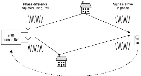
Beamforming is a general signal processing technique used to control the directionality of the reception or transmission of a signal. In cellular communication systems, base station’s antennas work together, as an array, in order to create a synthetic directional antenna beam, which has a main
24
beam pointing at a given UT, and a null pointing towards the other UTs. The beam width is narrower than one from a single antenna, so the transmitter power is focused towards the intended UT. As a result, we can increase the range of a base station in the direction of said UT. This is achieved by combining elements in a phased array in such way that at particular angles the antennas signals experience constructive interference while others experience destructive interference.
So, it is possible to adjust the amplitudes and phases of the transmitted signals, by applying a suitable set of antenna weights. In a system with antennas, this allows us to adjust the direction of the main beam and up to nulls or side lobes [2].
Figure 15 - Beamforming [14]
In OFDMA, we are able to process different sub-carriers using different sets of antenna weights, in order to create a synthetic antenna beam directed at any direction. It is then possible to communicate with several different mobiles at once, using different subcarriers, even if those mobiles are in completely different locations.
The use of beamforming works best if the antennas are close together, with a separation comparable with the wavelength of the radio waves, because it ensures that the signals sent or received by the antennas are highly correlated. This is a different situation from diversity processing or spatial multiplexing, which work best if the antennas are far apart, with uncorrelated signals. A base station is therefore likely to use two sets of antennas: a closely spaced set for beamforming and a widely spaced set for diversity and spatial multiplexing.
25
4. Long-Term Evolution System
In this Chapter we briefly present the LTE standard, also known as 4G cellular systems. The goal of LTE is to provide a high-data-rate, low-latency and packet optimized radio-access technology supporting flexible bandwidth deployments [15].In order to support packet-switched traffic with seamless mobility, a new network architecture was designed, simplified into a IP based system, increasing the quality of service and reaching a minimum latency.
In the previous cellular systems, there were some fragmentations between different standards used. The second generation of cellular systems had TDMA based GSM and CDMA based IS-95, the third generation had UMTS and CDMA2000. But now, with the introduction of LTE, the fourth generation of cellular systems has a global standard. The first LTE proposal was in 2004 by NTT DoCoMo of Japan but the standard was only created in 2005. The world’s first publicly available LTE service was lunched by TeliaSonera in Oslo and Stockholm on December 14, 2009 [16].
LTE was required to deliver a peak data rate of 100Mbps in the downlink and 50Mbps in the uplink. This requirement was exceeded in the eventual system, which delivers peak data rates of 300Mbps and 75Mbps respectively. For comparison, the peak data rate of WCDMA, in Release 6 of the 3GPP specifications, is 14Mbps in the downlink and 5.7Mbps in the uplink [2]. However, this peak data rates can only be achieved in optimal conditions, and are hard to achieve in a realistic scenario.
Within the specifications of the LTE system, there’s a support for flexible bandwidth, thanks to the OFDMA and SC-FDMA access schemes. In addition to FDD (Frequency Division Duplexing) and
26
TDD (Time Division Duplexing), half-duplex FDD is also allowed to support low cost UTs. Unlike FDD, in a half-duplex FDD operation a UT is not required to transmit and receive at the same time, thus avoiding the need for a costly duplexer in the UT. The system is optimized for low speeds, up to 15km/h. However, the system specifications allow mobility support in excess of 350km/h with some performance degradation.
Since OFDMA has high PAPR, it requires inefficient power amplifiers and it would reduce the autonomy of mobile devices significantly. Being so, the uplink access is based on single carrier frequency division multiple access (SC-FDMA) that promises increased uplink coverage due to low PAPR relatively to OFDMA. While maintaining the same site location deployed in HSPA, the LTE system was able to improve the cell-edge throughput, and can have cell coverage between 5 and 100km. In terms of latency, the LTE radio-interface and network provides capabilities for less than 10ms latency for the transmission of a packet from the network to the UE.
Also defined in the standard, there are several modulation schemes available for the transmission of data. Higher modulation orders increase the data rate with the inconvenient of being more susceptible to signal errors and path loss. This means that the distance between the base stations and the mobile terminals matters in the selection of the modulation scheme. For the downlink the main modulation schemes supported are QPSK, 16-QAM and 64-QAM, while for the uplink 64-QAM is optional at the UT. Figure 16 illustrates the selection of modulation scheme, according to the SNR, assuming that a greater distance implies a lower SNR.
The principal system attributes of the LTE system are summarized in the next table:
Table 1 - LTEs' system attributes [3]
Bandwidth 1.25 – 20 MHz
Duplexing FDD, TDD, half-duplex FDD
Mobility 350km/h
Multiple Access Downlink OFDMA
Uplink SC-FDMA
MIMO Downlink 2 x 2, 4 x 2, 4 x 4
Uplink 1 x 2, 1 x 4
Peak data rate in 20MHz
Downlink 173 and 326 Mb/s for 2 x 2 and 4 x 4 MIMO respectively
Uplink 86Mb/s with 1 x 2 antenna
configuration
Latency < 10ms
Modulation QPSK, 16-QAM and 64-QAM
Channel coding Turbo code
Other techniques
Channel sensitive scheduling, link adaptation, power control, ICIC and hybrid ARQ
![Figure 2 - Subscriptions of Cellular Systems [7]](https://thumb-eu.123doks.com/thumbv2/123dok_br/15992314.1103042/25.892.113.750.129.487/figure-subscriptions-cellular-systems.webp)
![Figure 4 - Transmitter and Receiver of an OFDMA system [8]](https://thumb-eu.123doks.com/thumbv2/123dok_br/15992314.1103042/33.892.288.624.144.465/figure-transmitter-receiver-ofdma.webp)

![Figure 12 - Reducing fading by using receiver diversity [3]](https://thumb-eu.123doks.com/thumbv2/123dok_br/15992314.1103042/41.892.158.722.494.776/figure-reducing-fading-using-receiver-diversity.webp)
![Figure 15 - Beamforming [14]](https://thumb-eu.123doks.com/thumbv2/123dok_br/15992314.1103042/46.892.177.619.349.636/figure-beamforming.webp)
![Figure 17 - Network Architecture [4]](https://thumb-eu.123doks.com/thumbv2/123dok_br/15992314.1103042/49.892.335.633.588.906/figure-network-architecture.webp)