Influence of Graphite Particles on Surface Roughness and
Chip Formation Studies in Turning Metal Matrix Composites
S. Basavarajappaa*, J. Paulo Davimb
aDepartment of studies in Mechanical Engineering, University BDT College of Engineering, Davangere-577004, India
bDepartment of Mechanical Engineering, University of Aveiro, Campus Santiago, 3810-193 Aveiro, Portugal
Received: October 21, 2012; Revised: January 31, 2013
This study presents an experimental investigation on surface roughness and chip formation in turning of Al 2219/15SiCp and Al 2219/15SiCp-3Gr (hybrid) composites. Experiments were conducted with different cutting conditions using carbide, coated carbide and polycrystalline diamond (PCD) tools. The results reveal that the surface roughness values are less for coated carbide tools compared to carbide and are minimum for PCD tools. The incorporation of graphite in Al 2219/15SiCp composite increases the surface roughness. This is due to smearing and removal of softer and amorphus graphite particles on the surface of the specimen, creates pits on the machined surface which increases the surface roughness values. The graphitic composite produced discontinuous chips leads to easy machining. PCD tool performs better than carbide and coated carbide tools.
Keywords: graphite, metal-matrix composites (MMCs), surface roughness, chip formation
1. Introduction
Composite materials exhibits better properties compared to conventional alloys in various applications as they have high specific strength, stiffness and better wear resistance, metal matrix composites are one among them. The Metal Matrix Composites (MMCs) are largely being used to replace conventional materials in many applications especially aerospace, automobile and recreational industries where the performance requirements are getting more demanding. Near net shape forming and casting is ideal for this type of composites but some kind of machining is essentially required to make the composites before the final assembly. Although these composites have excellent performance characteristics, their poor machining efficiency leads to severe cutting tool wear, and difficulty in obtaining the fine surface quality was explained in review by Basavarajappa et al.1.
Pramanik et al.2, Basavarajappa3 and Chou and Liu4 were reported that the main concern when machining of particulate metal matrix composites is extremely high tool wear and poor surface finish due to the abrasive action of the ceramic reinforcing particles compared to monolithic alloys. This is due to the presence of hard ceramic particles in composites, which acts as small cutting edges resulting in poor surface finish. Sometimes the hard-reinforced ceramic particles in the matrix will not be sheared off by cutting, but they are removed from the matrix, thereby creating voids on the surface5,6.
The machining conditions greatly influence the machining characteristics of metal matrix composites. These machining conditions are cutting speed, feed rate
and depth of cut. Medium cutting speeds are recommended for the machining of MMCs. Higher cutting speeds are not advantageous in all the cases except when PCD tools are used7,8. Gaitonde et al.9 identified that the medium cutting speed ranges from 200-450 m/min are recommended for carbide and coated carbide tools for better surface finish and reduced tool wear. The maximum cutting speeds used with PCD tools is up to 700 m/min. The selection of cutting speed in machining of MMC’s is highly dependent on the cutting tools used.
The machining conditions greatly influence the machining characteristics of metal matrix composites. These machining conditions are cutting speed, feed rate and depth of cut. Medium cutting speeds are recommended for the machining of MMCs. Higher cutting speeds are not advantageous in all the cases except when PCD and CBN tools are used9,10. Davim11 identified that the medium cutting speed ranges from 200-450 m/min are recommended for carbide and coated carbide tools for better surface finish and reduced tool wear. The maximum cutting speeds used with PCD tools is up to 700 m/min. The selection of cutting speed in machining of MMC’s is highly dependent on the cutting tools used. Kannan and Kishawy12 studied the tool wear, surface integrity and chip formation under both dry and wet cutting conditions during machining of A356/ 20% SiCp at particle size of 12 µm and Al7075/10% alumina at particle size of 15 µm. Turning tests were conducted using coated tungsten carbide cutting tools with different process parameters. In their investigation, they reported that the abrasive wear is the tool wear mechanism and the too wear of the cutting tool can be reduced only by using a tool that is harder than the reinforcement particles. The surface
roughness will increase marginally due to the application of coolant.
Sahin et al.13 reported that while turning Al
203 particle
reinforced composites the surface roughness increases with increase in particle volume fraction. The optimum surface roughness in turning obtained at cutting speed of 160 m/min for both TP30 and K10 tools. The maximum surface roughness value appeared in the turning of the 10% Al2O3 particles reinforced composite with particle size of 16 µm. Dabade et al.14 reported while machining
metal matrix composites with CBN tools with and without wiper on cutting edge. The microstructural analysis of the machined surface showed the number of feed marks, pits and cracks on the machined surface are significantly reduced using the wiper inserts, especially in the case of Al/SiC/30p composites. The presence of matrix coated fragments of reinforcement particles was evident on the machined surfaces.
It has been observed that the tendency of the chip to break up and facilitating its removal is greater with increased graphite content and finer graphite particles in aluminium alloy-graphite particle composites. Reduction in machining forces, surface roughness and chip thickness after increasing the graphite content to 6% in Al/Gr composites has been reported by Gibson et al.15. The machinability during turning of Al/Si/Gr composites was studied by Brown and Surappa16 and they are under the opinion that the reduction in machining forces with graphite reinforcement content is due to a decrease in the shear flow stress rather than to lower chip-rake-face friction. Ground and polished as well as machined surface of Al-Si alloy-graphite composites tend to be rougher than similar surface on similar material without graphite because of deeper holes or valleys. The incorporation of small amount of graphite results in reducing the cutting forces and tool wear significantly but with compromised conditions of surface finish.
Basavarajappa et al.17 studied the influence of various parameters on surface and subsurface deformation in drilling of Al/SiCp and Al/SiCp-Gr composites and they reported that the surface roughness of hybrid composite Al2219/15SiCp-3Gr is high when compared to Al2219/15SiCp. Surface roughness increases as feed rate increases and decreases as cutting speed increases. The subsurface deformation extends up to a maximum of 120 mm below the machined surface for Al2219/15SiCp-3Gr composite when compared to 150 mm in Al2219/15SiCp composite. Altunpak et al.18 studied the influence of drilling parameters on cutting force and surface roughness in drilling of Al/20SiC-5Gr and Al/20SiC-10Gr hybrid composites fabricated by liquid metallurgy route. They reported that the Surface finish is poor at drilling of Al/20SiC-10Gr composite compared to Al/20SiC-5Gr composites.
Studies related to chip formation in MMCs are very limited and not comprehensive. It is observed earlier that the deformation during machining of Al/SiCp composites was mainly due to the rupture rather than shear. The chips formed during machining show an asymmetrical waviness, with the chip segments joined to each other by a thin and highly strained region was reported2,19. It is also known from the theory of metal cutting that the study of chip formation
is the most effective and cheapest way of understanding machining characteristics of the work material.
The presence of reinforcement in composites alters the mode of chip formation considerably compared to the machining of monolithic alloys. SiC particles have high yield strength and their modulus of elasticity is very high, whereas the base alloy has low yield strength and a good plasticity. Thus in machining of the composites while the matrix deforms plastically and the SiC particles may only deform elastically or break. The reinforcing particles both SiCp and Graphite act as chip breakers in turning of Metal Matrix composites20-22.
Analysis of prior research shows that the effect of turning on surface roughness of hybrid metal matrix composites has not been adequately addressed. This is significant because these factors play an important role in the performance of the machined component. Therefore, this study presents the results of a detailed experimental investigation to determine the effect of cutting parameters and tool material on surface roughness and chip formation on turning of Al2219/15SiCp and Al2219/15SiCp-3Gr composites.
2. Materials and Experimental Procedure
2.1.
Material
Aluminium, which is the second most abundant metallic element on the earth and an economic competitor in engineering materials. The metal matrix selected for present investigation was based on Al-Cu-Mg alloy system, designated by the American Aluminium Association as AA 2219. The SiC particles, which were used to fabricate the composite, had an average particle size of 23 µm and average density of 3.2 g/cm3. It is the second hardest material after diamond with a Mohr’s hardness of 9.5. The graphite particles used for hybrid composites are of 45 µm size and average density of 2.25 g/cm3. The composites were fabricated by using liquid metallurgy technique.
2.2.
Experimental
Turning operations were conducted on composite specimen to measure the surface roughness and the chips formed. Work piece material used for the turning operations are Al 2219 alloy with 15% SiCp reinforcement and Al 2219 alloy with 15% SiCp and 3% Gr. Specimen were used in the form of cylindrical rod of 25 mm diameter and 300 mm length. The tooling system used was shown in the Table 1. The machining tests were performed for 50 mm length of continuous turning under dry conditions on a CNC Lathe. The cutting parameters used were shown in Table 2. The surface roughness was measured using surtronic 3+ Taylor Hobson Talyrond stylus instrument. The surface roughness (Ra) was measured thrice around the turned specimen surface and the average was taken for the analysis.
3. Results and Discussions
3.1.
Effect of cutting conditions
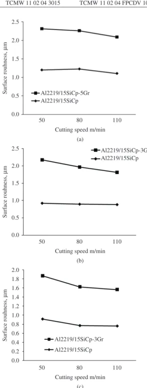
Figure 1 shows the variation of surface roughness with cutting speed for both the composites at a constant length of cutting of 50 mm, feed rate of 0.075 mm/rev and at depth of cut of 0.3 mm with carbide, coated carbide and PCD tools. The test results have indicated that the value of surface roughness Ra is high at low cutting speeds and low at high cutting speeds. This may be attributed to the burnishing or honing effect produced by the rubbing of small SiC particles trapped between the flank face of the tool and the workpiece surface23. Similar results were obtained by many
other researchers and reported that during the machining of SiCp reinforced composites with both carbide and PCD inserts5,7,12. At lower cutting speeds the surface roughness
is high due to the inability of the cutting tool to cut these particles, therefore, a high cutting speed is required to machine this composite13. Sometimes during turning, it was
observed that the surface roughness value is abruptly higher than the trend value. The abrupt irregularity in the values of surface roughness may be due to the presence of hard ceramic reinforcement particles i.e. SiCp which rolls over the surface during turning and ploughs the turned surface resulting in grooves on the machined surface. In case of graphitic composites, fractured SiCp particles will squeeze the graphite and forms a valley on the machined surface. The surface roughness values are less for coated carbide tools compared to the carbide tool and are minimum for PCD tools.
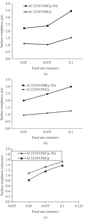
Figure 2 shows the effect of feed rate on the surface roughness for both the composites at a cutting speed of 80 m/min and a depth of cut of 0.3 mm. Experimental results show that the surface roughness value increases with increase in feed rate at all cutting conditions. This was attributed to high temperature in the cutting zone. Higher feed rate values increases temperature and this cause to decrease bonding effect between SiC particles and Al alloy matrix13. The surface roughness values for
the graphitic composites are higher compared to SiCp reinforced composites. Turning of SiCp and SiCp-Gr reinforced composites with PCD tool has show that the
Figure 1. Variation of surface roughness (Ra) with cutting speed for both the composites at a constant length of cutting of 50 mm, feed rate of 0.075 mm/rev and at DOC 0.3 mm for (a) carbide tool (b) Coated Carbide tool and (c) PCD tool.
Table 1. Details of tools used for turning.
Carbide Coated carbide PCD
Manufacturer SANDVIK SANDVIK SANDVIK
Rake angle (γ) 0° 0° 0°
Clearance angle (θ) 7° 7° 7°
Entry angle (ε) 93° 93° 93°
Nose radius (r) 0.4 mm 0.4 mm 0.4 mm
Designation TCMT 11 02 04 UF H13A TCMW 11 02 04 3015 TCMW 11 02 04 FPCDV 10
Table 2. Details of the cutting parameters used.
S. No. Parameters Range
1 Cutting speed (m/min) 50, 80, 110 2 Feed rate (mm/rev) 0.05, 0.075, 0.1 3 Depth of cut (mm) 0.3, 0.6, 0.9
Figure 3 shows the variation in surface roughness values with the increase in depth of cut for all cutting conditions. As depth of cut increases, the cutting forces and surface deformation increases which leads to increase in surface roughness values. When the depth of cut is tripled, the surface roughness value increases two times in the case of SiCp reinforced composites and three times in case of graphitic composites.
Figure 2. Variation of surface roughness (Ra) with feed rate for both the composites at a constant cutting distance of 50 mm, cutting speed of 80 m/min, depth of cut of 0.3 mm (a) carbide tool (b)Coated Carbide tool and (c)PCD tool.
surface roughness values increases with increase in feed rate almost linearly and the values are less when compared to carbide and coated carbide tools. This is because of high hardness of PCD tool when compared to SiC particles. PCD tools can cut the particles during machining. The experiments reveal that feed rate influences surface finish more than the cutting speed, these results are in agreement with other researchers13,24.
3.2.
Effect of graphite
The surface roughness value of Al/SiCp composites are less than that of hybrid graphitic composites for all cutting conditions. The higher surface roughness values in graphitic composites are attributed to the reduced burnishing or honing effect because of the presence of graphite film which will reduce the coefficient of friction between the tool and the workpiece. Hence, it allows the cutting tool to slide easily over the materials. The graphite particles being less dense and soft are easily smeared on the workpiece surface. The pits and valleys formed due to the smearing and removal of graphite particles from the surface of the workpiece generates voids on the surface of the component leads to higher surface roughness values. The SiCp particles between cutting tool and work piece easily removes the graphite particles from the surface of the work piece creating craters on surface of the machined surface. Rajmohan et al.25 reported that the increase in content of the soft reinforcement (mica) increases the surface roughness for all cutting conditions. Less dense mica acts as a weak spot region. When the tool passes over these regions, the crushed mica particles form a deep gorge and hence increase the surface roughness of the material. Similar result was given by Muralikrishnan and Raja26.
3.3.
Chip formation studies
The cutting of SiC particle reinforced aluminum composites results in various types of chip formation. When
the cutting tool edge only cuts the matrix and does not meet SiC particles, plastic deformation takes place. When the reinforcing particle boundary is poor, the boundary crack occurs resulting in a shear-break cutting. If the shear deformation of the matrix is hindered by reinforcing particles, squeeze-break and collapse cutting will occur22.
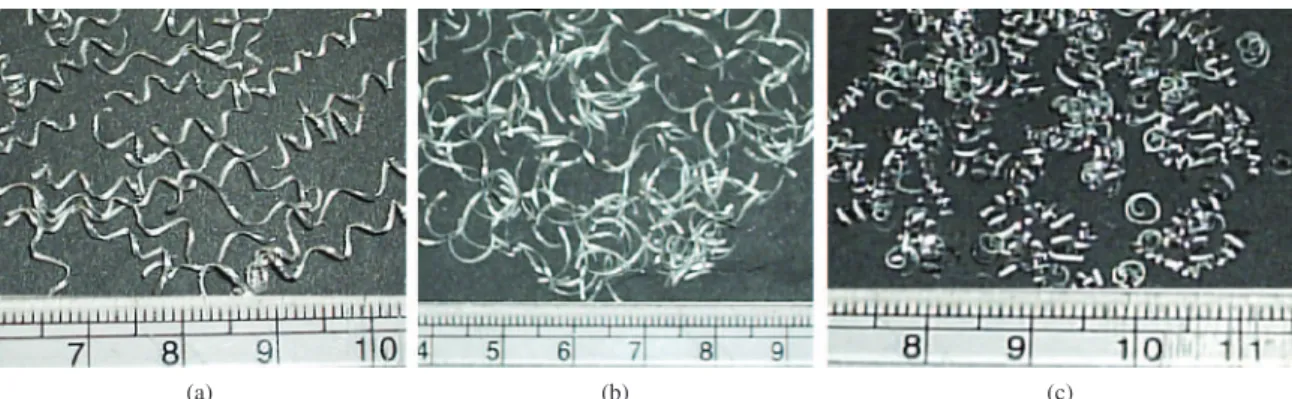
Figures 4 and 5 shows shape of the chips formed during dry turning of Al/SiCp and Al/SiCp-Gr composites using carbide, coated carbide and PCD tools at a cutting speed of 110 m/min a feed rate of 0.1 mm/rev and at a depth of cut of 0.3 mm. The chips (Figure 4a) formed are of saw tooth shape with high radius of curling and broken into small pieces.
From the chip appearance, it can be observed that cracks and voids were frequently formed on the outer face of the chips. It can be observed from Figure 4b that the chips were formed in semi-continuous, semi-circular or semi-parabolic form with large radius. From the Figure 4c it can be observed that the chips are spiral shaped with shining surface.
Figure 5 shows the chips formed during machining with carbide, coated carbide and PCD tools respectively when turning graphitic composites. The chips formed when turning of graphitic composites are similar to that of SiCp reinforced composites except that chips are shorter in graphitic composites and frequently cracks are formed on the outside surface of the chips.
The addition of SiCp and SiCp-Gr particle reinforcement to the aluminium matrix reduces the ductility and makes the material ideal for producing saw-toothed and segmental
Figure 4. Chips formed during the machining of Al 2219/SiCp for both the composites at a constant cutting distance of 50 mm, cutting speed of 110 m/min, feed rate of 0.1 mm/rev, depth of cut of 0.3 mm for (a) carbide tool (b) Coated Carbide tool and (c)PCD tool.
type chips during machining. During machining, it can be observed that when the material has undergone shear by the movement of the cutting tool during the chip forming process, cracks were initiated from the outside free surface of the chip and some small voids were formed by the separation of SiCp particles and Al matrix within the chip. Once this material was sheared further, the coalescence of the voids caused the crack to grow and propagate in a zig-zag manner along the shear plane through the thickness of this chip, resulting in fracture takes place and sliding of material forming the segmental chips.
It is also observed that during machining, propagation of cracks is accelerated by the upward and side curling action of the chip, which from time to time, helps to break a long chip into smaller pieces. The line of crack propagation through the matrix material seems to develop along the stress concentration zone, i.e. at the edge of the SiC particles inside the Al-matrix. The crack line is propagated towards the boundary of the SiC particles as Al/SiC interface seems to be a plane of weakness. Thus the crack propagates from SiC particle to SiC particle through some ductile fracture
process through development of fracture by overcoming the bonding strength between the SiC particle and Al-matrix. In case of graphitic composites the soft particles acts like a chip breakers and helps to generate serrated chips of smaller length.
4. Conclusions
The incorporation of graphite particles into aluminium MMCs and the variation of hard SiC particle content increases the surface roughness i.e in Al 2219/15SiCp-3Gr compared to graphite free composites. The pits and valleys formed due to the smearing and removal of graphite particles from the surface of the workpiece generates voids on the surface of the component leads to higher surface roughness values. The SiCp particles between tool and work piece easily removes the graphite particles from the surface of the work piece creating craters on surface of the machined surface. Better surface finish can be obtained at highest speed and lowest feed. The PCD tool performs better than other tools used in the study. The graphitic composites produce discontinuous chips leads to easy machining.
References
1. Basavarajappa S, Chandramohan G, Narasimha Rao KV and Radhakrishan R. Turning of particulate Metal Matrix Composites- Review and Discussion. Journal of Manufacturing Engineering Part-B, IMechE. 2006; 246:1189-1204. http:// dx.doi.org/10.1243/09544054JEM304
2. Pramanik A, Zhang LC and Arsecularatne JA. Machining of metal matrix composites: Effect of ceramic particles on residual stress, surface roughness and chip formation. International Journal of Machine Tools & Manufacture. 2008; 48:1613-1625. http://dx.doi.org/10.1016/j.ijmachtools.2008.07.008
3. Basavarajappa S. Tool wear in turning of metal matrix composites. Materials and Manufacturing Processes. 2009; 24:484-487. http://dx.doi.org/10.1080/10426910802714431
4. Chou YK and Liu J. CVD diamond tool performance in metal matrix composite machining. Surface & Coatings Technology. 2005; 200:1872-1878. http://dx.doi.org/10.1016/j. surfcoat.2005.08.094
5. Kok M. Tool life modeling for evaluating the effects of cutting speed and reinforcements on the machining of particle reinforced metal matrix composites. International Journal of Minerals, Metallurgy and Materials. 2010; 17(3):353-362. http://dx.doi.org/10.1007/s12613-010-0318-4
6. Palanikumar K, Muthukrishnan N and Hariprasad KS. Surface roughness parameters optimization in machining A356/ SiC/20p metal matrix composites by PCD tool using response surface methodology and desirability function. Machining Science and Technology. 2008; 12(4):529-545. http://dx.doi. org/10.1080/10910340802518850
7. Sahin Y and Sur G. The effect of Al2O3, TiN and Ti (C,N) based CVD coating on tool wear in machining metal matrix composites. Surface and Coating Technology. 2004; 179:349-355. http://dx.doi.org/10.1016/S0257-8972(03)00802-8
8. Sadat AB. On the quality of machined surface region when turning Al/SiC metal matrix composites. Machining Science and Technology. 2009; 13(3):338-355. http://dx.doi. org/10.1080/10910340903237731
9. Gaitonde VN, Karnik SR and Davim JP. Some studies in metal matrix composites machining using response surface methodology. Journal of reinforced plastics and composites. 2009; 28(20):2445-2457. http://dx.doi. org/10.1177/0731684408092375
10. Zhong ZW and Hung NP Diamond turning and grinding of aluminium-based metal matrix composites. Materials and Manufacturing Processes. 2000; 15:853-865. http://dx.doi. org/10.1080/10426910008913026
11. Davim JP. Turning particulate metal matrix composites: experimental study of the evolution of the cutting forces, tool wear and workpiece surface roughness with the cutting time. IMechE-Journal Engineering Manufacture Part B. 2001; 215:371-376. http://dx.doi.org/10.1243/0954405011515433
12. Kannan S and Kishawy HA. Tribological aspects of machining aluminium metal matrix composites. Journal of Materials Processing Technology. 2008; 198:399-406. http://dx.doi. org/10.1016/j.jmatprotec.2007.07.021
13. Sahin Y, Kok M and Celik H. Tool wear and surface roughness of Al2O3 particle-reinforced aluminium alloy composites. Journal of Materials Processing Technology. 2002; 128:280-291. http://dx.doi.org/10.1016/S0924-0136(02)00467-3 14. Dabade UA, Joshi SS, Balasubramaniam R and Bhanuprasad
VV. Surface finish and integrity of machined surfaces on Al/SiCp composites. Journal of Materials Processing Technology. 2007; 192-193:166-174. http://dx.doi. org/10.1016/j.jmatprotec.2007.04.044
15. Gibson PR, Clegg AJ and Das AA. Production and evaluation of squeeze- cast graphitic composites. Material Science and Technology. 1985; 1:559-567. http://dx.doi. org/10.1179/026708385790124459
16. Brown CA and Surappa MK. The machinability of a Cast Aluminium alloy - Graphite Particle composite. Material Science Engineering A. 1988; 102:31-37. http://dx.doi. org/10.1016/0025-5416(88)90530-7
and Manufacture. 2007; 47:92-96. http://dx.doi.org/10.1016/j. ijmachtools.2006.02.008
18. Altunpak Y, Ay M and Aslan S. Drilling of a hybrid Al/SiC/Gr metal matrix composites. International Journal of Advanced Manufacturing Technology. 2012; 60:513-517. http://dx.doi. org/10.1007/s00170-011-3644-4
19. Dabade UA and Joshi SS. Analysis of chip formation mechanism in machining of Al/SiCp metal matrix composites. Journal of Materials Processing Technology. 2009; 209:4704-4710. http://dx.doi.org/10.1016/j.jmatprotec.2008.10.057
20. Tomac N and Tonnesson K. Machining of particulate Al matrix composites. Annals of CIRP. 1992; 41:55-58. http://dx.doi. org/10.1016/S0007-8506(07)61151-2
21. Songmene V and Balazinski M.Machinability of graphitic metal matrix composites as a function of reinforcing particles. Annals of CIRP Manufacturing Technology. 1999; 48:77-80. http://dx.doi.org/10.1016/S0007-8506(07)63135-7
22. Quan YM, Zhou ZH and Ye BY. Cutting process and c h i p a p p e a r a n c e o f a l u m i n i u m m a t r i x c o m p o s i t e reinforced by SiC particle. Journal of Material Processing
Technology. 1999;91:231-235. http://dx.doi.org/10.1016/ S0924-0136(98)00444-0
23. Basavarajappa S, Chandramohan G, Davim JP, Prabu M, Mukund K, Ashwin M et al. Drilling of hybrid aluminium matrix composites. International Journal of Advanced Manufacturing Technology. 2008; 35:1244-1250. http://dx.doi. org/10.1007/s00170-006-0804-z
24. Bhushan RK, Kumar S and Das S. Effect of machining parameters on surface roughness and tool wear for 7075 Al alloy SiC composite. International Journal of Advanced Manufacturing Technology. 2010; 50:459-469. http://dx.doi. org/10.1007/s00170-010-2529-2
25. Rajmohan T, Palanikumar K and Kathirvel M. Optimization of machining parameters in drilling hybrid aluminium metal matrix composites. Transactions of Nonferrous Metals Society of China. 2012; 22:1286-1297. http://dx.doi.org/10.1016/ S1003-6326(11)61317-4