Abstract
Low-velocity impact of a nanocomposite beam made of glass/epoxy reinforced with multi-wall carbon nanotubes and clay nanoparticles is investigated in this study. Exerting modified rule of mixture (MROM), the mechanical properties of nanocomposite including matrix, nanoparticles or multi-wall carbon nanotubes (MWCNT), and fiber are attained. In order to analyze the low-velocity impact, Euler-Bernoulli beam theory and Hertz s contact
law are simultaneously employed to govern the equations of mo-tion. Using Ritz s variational approximation method, a set of
nonlinear equations in time domain are obtained, which are solved using a fourth order Runge-Kutta method. The effect of different
parameters such as adding nanoparticles or MWCNT s on
maxi-mum contact force and energy absorption, stacking sequence, geometrical dimensions (i.e., length, width and height), and initial velocity of the impactor have been studied comprehensively on dynamic behavior of the nanocomposite beam. In addition, the result of analytical model is compared with Finite Element Model-ing (FEM).The results reveal that the effect of nanoparticles on energy absorption is more considerable at higher impact energies.
Keywords
Low-velocity impact; Nanocomposite beam; Nanoclay; Carbon
Low-velocity Impact Response of a Nanocomposite
Beam Using an Analytical Model
1 INTRODUCTION
Composite structures are widely used in many engineering applications. Owing to unique properties, these materials are proper substitutes for traditional metals. Some mechanical properties such as high strength to weight ratio, fatigue and wear resistance, and formability of intricate shapes in-crease a widespread use of composites in industries such as aerospace and military in which weight plays an important role.
Mahdi Heydari Meybodi a Saeed Saber-Samandari b Mojtaba Sadighi a
Mohammad Reza Bagheri a
a Composite Research Lab., Thermo-elasticity Center of Excellence, Depart-ment of Mechanical Engineering, Amir-kabir University of Technology, Tehran, Iran
b New Technologies Research Center,
Amirkabir University of Technology, Tehran, Iran
Corresponding author:
Saeed Saber-Samandari [email protected]
http://dx.doi.org/10.1590/1679-78251346
Latin A m erican Journal of Solids and Structures 12 (2015) 333-354
On the other hand, utilizing particles at nanoscale have been recently taken into consideration. Since the manufacturing of nanoclay/epoxy nanocomposites in 1993 (Kojima et al., 1993) and
car-bon nanotubes in 1991 (Iijima, 1991), many investigations have been carried out on these types of nanocomposites over the past decade. Nanocomposites have some unique properties such as high elastic modulus (Saber-Samandari and Afaghi-Khatibi, 2007; Saber-Samandari and Khatibi, 2006), high tensile strength (Saber-Samandari et al., 2007), thermal resistance, flame retardancy, high
fracture toughness (Xu and Hoa, 2008), optical properties and dimensional stability (Utracki, 2004), and water resistance (Zhou et al., 2008) by adding slight amount of nanofillers.
Carbon nanotubes have been incorporated into polymers as a new generation of reinforcing agent for composite materials under low-velocity impact (Ramakrishnan et al., 2014; Taraghi et al., 2014).
Taraghi et al.(2014) investigated the low-velocity impact on a Kevlar/epoxy/carbon nanotube
plate. Their experimental results showed that for the specimens at room temperature and -40 C,
adding a carbon nanotube to epoxy will increase the energy absorption, penetration limit, and bend-ing stiffness and decrease the damage area.
Few studies have been conducted on the dynamic analysis of nanocomposite beams so far. Vi-bration analysis of a functionally graded carbon nanotube-reinforced beam was reported (Heshmati and Yas, 2013; Ke et al., 2010; Yas and Heshmati, 2012). Wuite and Adali (2005) examined the
deflection and stress in a nanocomposite carbon/polyester/nanotube beam subjected to a concen-trated force at the beam center. They analyzed the beam using classical laminate theory and did
not incorporate Hertz s law in their analysis. Studying the pure bending and local buckling of a single wall carbon nanotube (SWCNT) reinforced composite beam by developing a continuum me-chanics model (Vodenitcharova and Zhang, 2006), and free vibration and buckling of a carbon nanotube-reinforced composite beam on an elastic foundation (Yas and Samadi, 2012) are other works done on the dynamic behavior of nanocomposite beams.
Most of the research in regard to the low-velocity impact on nanocomposite structures has been mainly on plates and many of them were implemented experimentally. Lin et al.(2006)
experimen-tally investigated the effect of two different types of nanoparticles namely, titanium dioxide and cloistie nano-powder during which no fiber was used in their analysis. Low-velocity impact of a nanoclay-reinforced composite plate (Gustin et al., 2005) at -40, 23.9, and 65.6 C shows that the
specimen at -40 degrees has 29 percent energy absorption less than pure matrix, while the behavior of two other specimens is the same. Hosur et al.(2007) investigated low-velocity impact of a plate
with a specific type of nanoclay and plain weave carbon/epoxy composite laminates. It was shown that the variation of nanoclay percentage had not much effect on maximum contact force. They also studied the damage area due to low-velocity by exploiting the C-scan method, which is an ul-trasonic nondestructive method. By the results it can be concluded that the specimen containing 1 % of nanoclay possesses the lowest damage area among others. Low-velocity impact on a Kev-lar/epoxy plate shows that adding nanoclay will increase the residual tensile strength (Reis et al.,
2013). The plate containing 6 % of nanoclay possesses the best penetration threshold and the lowest deflection in comparison with other specimens.
Latin A m erican Journal of Solids and Structures 12 (2015) 333-354 nanoclay and carbon nanotube-reinforced composite beam is studied. Exploiting Ritz s variational approximation method, an approximate function for the deflection is estimated and the obtained set of time domain equations are solved using a numerical technique (Runge-Kutta fourth order) via MATLAB code. The effect of some parameters like the percentage of nanoparticles on maximum contact force, energy absorption, stacking sequence, energy variation with respect to time, initial velocity of the impact and geometrical dimensions of the beam (i.e., length, width and height) are studied. In addition, the result of analytical model is compared with Finite Element Modeling (FEM).
2 GOVERNING EQUATIONS
2.1 Low-velocity impact on a composite beam
To obtain the governing equations of the low-velocity impact with spherical impactor on a compo-site beam, the relations for an isotropic beam in reference (Abrate, 1998) has been expanded. By neglecting the rotary inertia effects and considering symmetric lay-up, the motion equation of a composite beam is acquired based on the Euler-Bernoulli beam theory with the dimension of L , b
and h (as length, width and thic’ness of the beam, respectively) as bellow:
4 2
11 4 1 2
w w
D I p
x t (1)
Where I1 is the mass per unit length and is given as follows:
/2 /2
1
h
h
I b dz b h (2)
To compute D11 in a laminate containing n number of layers, Eq. (3) can be used:
3 3
11 11 1
1 ( 1 3 ) n k k k k
D b Q h h (3)
Where:
4 4 2 2
11 11 22 12 66
11 22 12 22
11 22 12
12 21 12 21 12 21
66 12
cos ) sin ) 2( 2 )cos )sin )
,
( ( ( (
,
1 1 1
Q Q Q Q Q
E E E
Q Q Q
Q G
(4)
The transverse displacement of the beam (deflection) using Ritz s approximation can be expressed
as follows: 1 ( , ) () ( ) N j j j t W x
Latin A m erican Journal of Solids and Structures 12 (2015) 333-354
Where N is the dynamic modes and j is the shape function which has to satisfy the essential boundary conditions.
As an example, for a beam with built-in edge at both ends, w w 0
x at the edges and for a
beam with simply-supported edges only w=0.
By substituting the Equation 5 for the deflection of the beam into the equation of motion based on the Euler-Bernoulli theory (Equation 1), following sets of equations are obtained:
( )
i i i i i
mW kW f t (6)
Where m , ’ and f are mass matrix, stiffness matrix and force vector, respectively. By ta’ing b
as the width of the beam, the elements of the above matrix can be given by:
A cronym s and N om enclatures
ρ Density of laminate (Kg/m3)
θ Ply angle
ν , ν In-plane Poisson's ratio
ν Poisson's ratio of fiber
νq,m Equivalent Poisson's ratio of matrix and nanoparticle set
Shape function
a Distance of concentrated force from the left edge of beam (m)
b Beam width (m)
D11 First component of bending stiffness matrix (Pa.m3)
E Longitudinal modulus (GPa)
E Transverse modulus (GPa)
E Elastic modulus of fiber (GPa)
Eq,m Equivalent elastic modulus of matrix and nanoparticle set (GPa)
f Force vector of beam (N)
F Force vector of the beam and impactor set(N) g Gravity acceleration (m/s2)
G In-plane shear modulus (GPa)
G Shear modulus of fiber (GPa)
G q,m Equivalent shear modulus of matrix and nanoparticle set (GPa)
h Beam height(Thickness) (m)
H Initial height of impact (m)
I1 Mass per unit length (Kg/m)
k Stiffness matrix of beam (N/m)
K Stiffness matrix of the beam and impactor set (N/m)
kc Contact stiffness of Beam (N/m1.5)
Kbs Target stiffness (N/m)
L Beam length (m)
m Mass matrix of beam (Kg)
M Mass matrix of beam and impactor set (Kg)
Mp Mass of the projectile (Kg)
Latin A m erican Journal of Solids and Structures 12 (2015) 333-354 A cronym s and N om enclatures (continuation)
N Number of dynamic modes
P Contact force (N)
p Exerted force on the beam (N/m)
Q Reduced stiffness matrix (Pa)
Q̅ Transformed reduced stiffness matrix (Pa)
R Radius of spherical projectile (m)
V0 Initial velocity of projectile (m/s)
Vf Volume fraction of fiber
Veq,m Volume fraction of matrix and nanoparticle set
Vfi Velocity of the projectile after impact (m/s)
w Transverse displacement of the beam (deflection)(m)
W Coefficients of Ritz s variational method
{X} Displacement vector for beam and impactor set (m)
{X} Velocity vector for beam and impactor set(m/s)
{X} Acceleration vector for beam and impactor set (m/s2)
KEB Kinetic energy of beam (J)
SEB Strain energy of the beam under pure bending (J)
TEB Total energy of beam (J)
KEP Kinetic energy of projectile (J)
(x 2 2
11
0 2 2
1 0 0 ) ( , ) ( ) * ) , ( , ,
L i T j
ij
L T
ij i j
L
i k
m I dx
f p x t dx
i
D dx
x x
t
(7)
In this equation, p x t( , )is applied force (per unit length) on the beam and the superscript T de-notes transposed matrix. Considering a concentrated force with a distance a from the left edge, the
force vector can be expressed in a more convenient form:
( ) ( )
i i
f t P a (8)
On the other hand, the equation of motion for the projectile is equal to:
0
px
M P (9)
Where P is the contact force and can be obtained from Hertz s Law (Abrate, 1998):
3 2
( ) c( ( ) ( , ))
P t k x t w a t (10)
In this equation, kc is the contact stiffness for the composite beam. Since the pro‘ectile is spherical
Latin A m erican Journal of Solids and Structures 12 (2015) 333-354
4 3
c
k E R where,
2 2
22,
1 1
1 p comp
p comp
v v
E E E (11)
In this equation, the subscripts 'p' and comp denote the pro‘ectile and composite beam, respectively.
Finally, the equation of motion for the beam and the projectile is represented as follows:
{ } { } { }
M X K X F (12)
In this equation, M and K are mass and stiffness matrices, respectively. It has to be mentioned
that these matrices are square of order N+1 and are described as follows:
11 12 1 21 22 2
1 2
11 12 1 21 22 2
1 2
0 0
0
0 0 0
0 0
0
0 0 0 0
N
N
N N NN
p
N
N
N N NN
m m m
m m m
M
m m m
M
k k k
k k k
K
k k k
(13)
Where mij and kij are the presented integral equations in Equation 7 and Mp is the mass of
the pro‘ectile. If the beam is initially at rest and the impact velocity of the pro‘ectile is V0 , initial
conditions to obtain the solution of the above equations can be exhibited as follows:
0
0 0 .
{0} {0} , {0}
. .
X X
V
(14)
Latin A m erican Journal of Solids and Structures 12 (2015) 333-354
2.2 Expanding equations for a Nanocomposite Beam
To analyze a nanocomposite beam under low-velocity impact, each of the following methods can be used:
1- Taking a Represented Volume Element (RVE) and continuing the analysis.
2- Procuring the equivalent properties of the nanocomposite beam and substituting them into the foregoing equations.
Since the nanoparticles disperse through the matrix, chemical bonds between the matrix and nano-particles are stronger than that of fibers. Therefore, the effect of nanonano-particles on the mechanical properties of the matrix is higher than the fibers. For this reason, the equivalent properties of ma-trix and nanoparticles were utilized here. According to Kollár and Springer (2003), the modified rule of mixture (MROM) is somewhat more complex than the rule of mixture (ROM), however it gives the transverse properties with better accuracy. Thus in this study, the modified rule of mix-ture is used to obtain the equivalent properties of the nanocomposite (Kollár and Springer, 2003):
11 , ,
, 1 22 , , , , 1 12 , , ,
12 , ,
22 21 12 11 ( ) ; 1 ( ) ; 1 1 ( ) ; 1 ; ( ) *
f f eq m eq m
f eq m
eq m
f f eq m eq m
f eq m
eq m
f f eq m eq m
f f eq m eq m
E E V E V
V V
E
E
V E V E
V V
G
G
V G V G
V V
E E
(15)
Where, the subscripts ′eq, m′denote the equivalent properties of matrix and nanoparticle and V , E , G and f denote volume fraction, elastic modulus, shear modulus and fiber, respectively.
3 RESULTS AND DISCUSSION
3.1 Verification of the method
3.1.1 Verification with Finite Element Modeling (FEM)
Since there was no experimental data available as to the low-velocity impact of nanocomposite beams in open literatures, the data obtained from the analytical model were compared with those in finite element model using LS-DYNA software.
In order to simplify the simulation, consider a nanocomposite beam with the layup of
[0 / 90 / 0 / 90 / 0]S
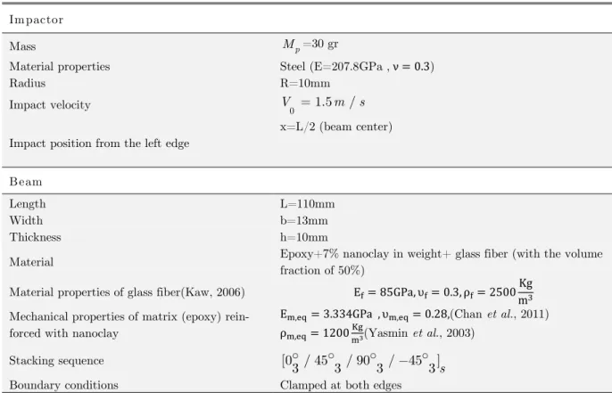
Latin A m erican Journal of Solids and Structures 12 (2015) 333-354 Im pactor
p
M =30 gr
Mass
Steel (E=207.8GPa , ν = . ) Material properties
R=10mm Radius
0 1.5 /
V m s
Impact velocity
x=L/2 (beam center) Impact position from the left edge
Beam
L=110mm Length
b=13mm Width
h=10mm Thickness
Epoxy+7% nanoclay in weight+ glass fiber (with the volume fraction of 50%)
Material
E = 8 GPa, = . , ρ = mKg
Material properties of glass fiber(Kaw, 2006)
Em, q= . GPa , m, q= . 8,(Chan et al., 2011)
ρm, q= mK3(Yasmin et al., 2003)
Mechanical properties of matrix (epoxy) rein-forced with nanoclay
[0 / 45 / 90 / 45 ]
3 3 3 3s
Stacking sequence
Clamped at both edges Boundary conditions
Table 1: Main parameters used in this study.
Each lamina was simulated in 3D using eight-node solid elements. To simulate the laminate MAT_2 (ORTHOTROPIC ELASTIC) was used and MAT_20 (RIGID) was utilized for the spher-ical rigid impactor.
Considering the mechanical properties of every single element in Table 1 and using MROM (equa-tion 15), the equivalent properties of the beam has been considered as follows:
1 44.17 , 2 3 10.06 , 12 3.957 , 13 23 3.868
E GPa E E GPa G GPa G G GPa
Latin A m erican Journal of Solids and Structures 12 (2015) 333-354 Figure 1: (a) Finite Element Modeling (FEM) of the impact on a nanocomposite
beam, (b) Force-time graph to verify this study with FEM.
Delamination modeling was considered as
CON-TACT_AUTOMATIC_SURFACE_TO_SURFACE_TIEBREAK and the contact for the im-pactor and beam was of type CONTACT_ERODING_SURFACE_TO_SURFACE. The ply ele-ment deleting criterion was applied by choosing ADD EROSION.
The related force-time graph is plotted in Figure (1-b).
Latin A m erican Journal of Solids and Structures 12 (2015) 333-354
3.1.2 Verification with composite beam
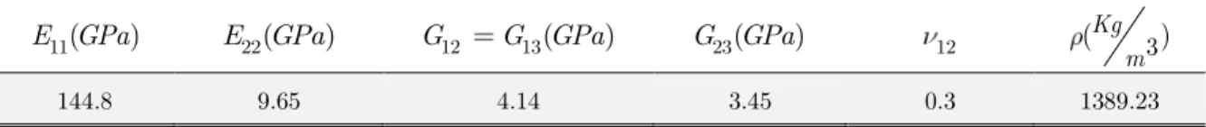
To the best knowledge of the authors, no experimental study has been carried out on the low-velocity impact of nanocomposite beams. As a result, the second verification of the problem is car-ried out with a low-velocity impact on a composite beam (Lam and Sathiyamoorthy, 1999). Consid-ering a steel spherical impactor with the radius of 10 mm and initial velocity of 2m/s and a car-bon/epoxy composite beam with the layup of [0/90/90/0], low velocity impact analysis is conduct-ed. Table 2 and Figure (2-a) depict the essential input parameters and equivalent properties, re-spectively. The boundary condition is taken as built-in edge at one end and symmetric boundary conditions at the other one.
11( )
E GPa E22(GPa) G12 G13(GPa) G23(GPa) 12 (Kg 3)
m
144.8 9.65 4.14 3.45 0.3 1389.23
Table 2: Material properties of graphite / epoxy (AS413501) (Lam and Sathiyamoorthy, 1999).
The essential boundary conditions are as follows:
. :
0 .
0 0
w
w a
E B C
t x x
w
at x L x
s (16)
The following shape mode function satisfies the above boundary conditions:
1* *
( )
i
i i
x x l x
cos x sin
i x
l l (17)
Latin A m erican Journal of Solids and Structures 12 (2015) 333-354 Figure 2: (a) Schematic of the impact on a composite beam to verify this study
(all dimensions in mm), (b) Force-time graph to verify this study.
3.2 Parametric studies
To investigate the effect of different parameters on low-velocity impact response of nanocomposite beams, the parametric study is accomplished and equivalent model and impactor information are represented in Table 1.
The boundary conditions are assumed to be built-in at both ends, which lead to the following essen-tial boundary conditions:
. . :
0 0
0
w
w at x
x w
w at
E
x L x
B Cs (18)
The approximate Ritz s function which satisfies the boundary conditions was ta’en as 2
1 cos i x
i L .
It has to be mentioned that the beam is taken as quasi-isotropic with 24 layers. The lay-up of
the composite is[0 / 45 / 90 / 45 ]
3 3 3 3swith glass fibers as reinforcement and epoxy resin with
Latin A m erican Journal of Solids and Structures 12 (2015) 333-354
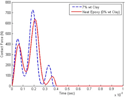
3.2.1 Effect of nanoclay presence on maximum force
The Young s modulus of various nanoclay/epoxy samples is presented in Table 3. Using the given values as the equivalent properties of matrix and nanoclay, as well as other required parameters in Table 1, the force-time graph for the specimen has 0 and 7 percent nanoclay and is plotted in Fig-ure 3. As it can be seen from FigFig-ure 3, maximum contact force for the specimen without the pres-ence of nanoclay is 637 N, while this Figure reaches to 725 N for the specimen with 7 % nanoclay in epoxy resin. Furthermore, adding nanoclay to epoxy resin reduces the contact time from 4.03 msec to 3.73 msec.
Sample Young s modulus(GPa) Percentage improvement of Young s modulus (%)
Neat epoxy 2.120 0
1 wt.% nanoclay– epoxy 2.474 16.7
3 wt.% nanoclay– epoxy 2.625 23.8
4 wt.% nanoclay– epoxy 2.771 30.7
5 wt.% nanoclay– epoxy 2.841 34.0
7 wt.% nanoclay– epoxy 3.334 57.2
9 wt.% nanoclay– epoxy 2.431 14.7
Table 3: Mechanical properties of epoxy/nanoclay at different percentages of nanoclay (Chan et al., 2011).
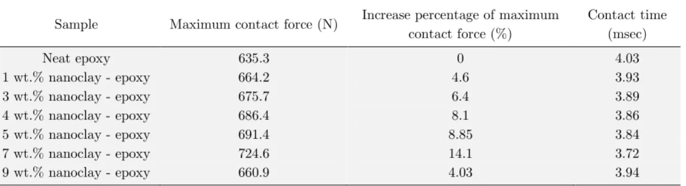
Latin A m erican Journal of Solids and Structures 12 (2015) 333-354 Figure 4 depicts the maximum force for various percentages of nanoclay in epoxy resin. Besides, total contact time and the increase of maximum force value can be observed in Table 4.As it can be seen from Figure 4, increasing the nanoclay percentage up to 7 % will increase the maximum con-tact force, while for the 9percent specimen, a reduction is observed for the maximum concon-tact force.
The reduction of Young s modulus for the specimen with 9 percent nanoclay can also be observed
from Table 3.
Sample Maximum contact force (N) Increase percentage of maximum
contact force (%)
Contact time (msec)
Neat epoxy 635.3 0 4.03
1 wt.% nanoclay - epoxy 664.2 4.6 3.93
3 wt.% nanoclay - epoxy 675.7 6.4 3.89
4 wt.% nanoclay - epoxy 686.4 8.1 3.86
5 wt.% nanoclay - epoxy 691.4 8.85 3.84
7 wt.% nanoclay - epoxy 724.6 14.1 3.72
9 wt.% nanoclay - epoxy 660.9 4.03 3.94
Table 4: Comparison of specimens behavior with different percentages of nanoclay under low-velocity impact.
Figure 4: Maximum contact force versus different percentages of nanoclay.
It is worth mentioning that during the preparation of specimens, intercalation and exfoliation pro-cesses have to be carried out carefully to avoid agglomeration phenomena. The reduction of
maxi-mum contact force and Young s modulus can be due to the stic’ing of nanoparticles together and
agglomeration phenomenon (Wuite and Adali, 2005). As can be inferred from the experimental data tabulated in Table3 and results of this study from Table 4, the increase percentage of the maximum
contact force is lower than the increase percentage of Young s modulus. In addition, the decrease of
Latin A m erican Journal of Solids and Structures 12 (2015) 333-354
3.2.2 Comparison of nanoclay and carbon nanotube effect on maximum contact force
In this section, the effect of nanoclay and carbon nanotube on the low-velocity impact response of a nanocomposite beam is compared.
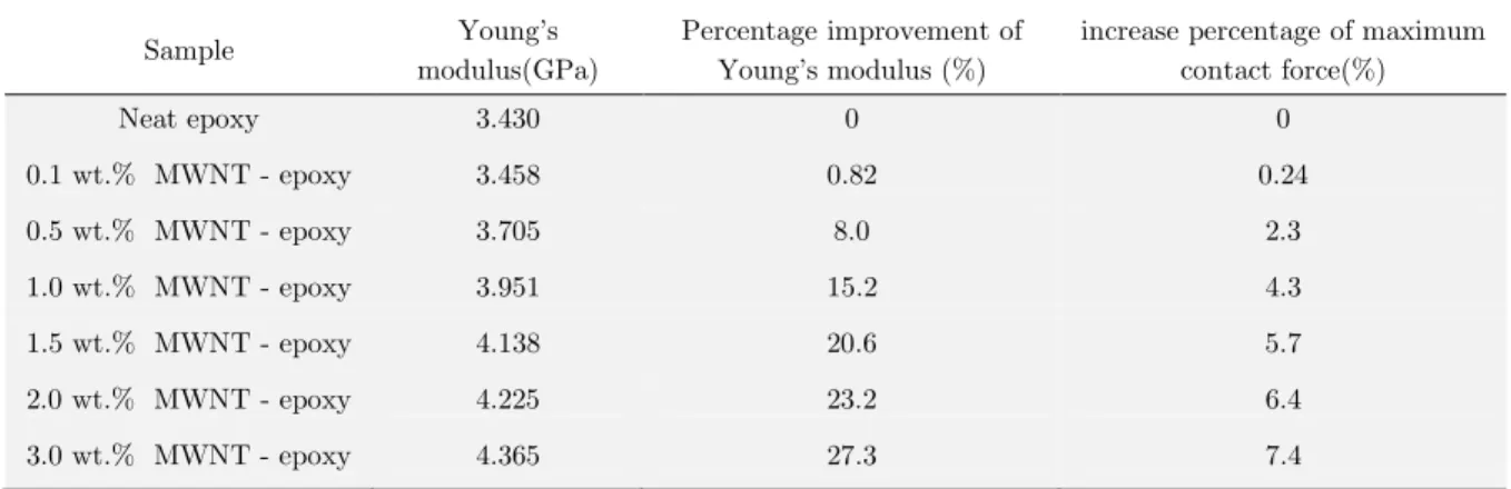
Since there was no report in the case of nanoclay/epoxy and CNT/epoxy composite with identical matrices, the increase of maximum contact force is investigated here. Mechanical properties of a multi-walled carbon nanotube (MWCNT)/epoxy are given in Table 5.
Sample Young s
modulus(GPa)
Percentage improvement of
Young s modulus (%)
increase percentage of maximum contact force(%)
Neat epoxy 3.430 0 0
0.1 wt.% MWNT - epoxy 3.458 0.82 0.24
0.5 wt.% MWNT - epoxy 3.705 8.0 2.3
1.0 wt.% MWNT - epoxy 3.951 15.2 4.3
1.5 wt.% MWNT - epoxy 4.138 20.6 5.7
2.0 wt.% MWNT - epoxy 4.225 23.2 6.4
3.0 wt.% MWNT - epoxy 4.365 27.3 7.4
Table 5: Mechanical properties of MWCNT/epoxy composite at different percentages of MWCNT (Montazeri et al., 2010).
Considering the data given in Table 1, maximum contact force of the beam with respect to different CNT percentages under low-velocity impact can be observed in Figure 5.Comparing the values re-lated to the percentage of maximum force increase in Tables 4 and 5, one can find that using lower MWCNT percentages leads to higher maximum contact force in comparison with nanoclay. In other words, the effect of MWCNT at lower percentages is more considerable with respect to nanoclay particles. It has to be mentioned that maximum contact force is of great importance because it brings about damage initiation in the structure.
Latin A m erican Journal of Solids and Structures 12 (2015) 333-354
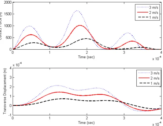
3.2.3 Effect of initial velocity on impact response
To investigate the effect of impact velocity, a beam with 7 percent nanoclay under low-velocity impact is considered here (see details in Table 1). Figure 6 shows the force-time graph plotted in three different projectile velocities, namely 1, 2 and 3 m/s. As it can be seen from Figure 6, the higher impact velocity gives rise to the higher-maximum contact force. On the contrary, the contact time decreases as the initial velocity increases. It can also be found that the increase in initial veloc-ity leads to an increase in maximum deflection of the nanocomposite beam. As it is known, the initial energy relation is as follows:
2 0
1
2M Vp M gHp (19)
Where H , Mp and V0 are initial height, mass of the pro‘ectile and initial velocity of the impact,
respectively. It can be concluded that any factor that increases the impact energy has a direct effect
on maximum contact force and maximum deflection. In other words, as V0 , H or Mp increases, maximum contact force and maximum deflection will both increase. Variations of parameters that cause no change in initial impact energy such as radius of the projectile (by assuming a constant mass, the percentage of nanoparticles, geometrical dimensions of the beam, etc., will have an inverse effect on the maximum deflection and maximum contact force. This means that the increase in maximum deflection gives rise to the decrease in maximum contact force and vice versa.
Latin A m erican Journal of Solids and Structures 12 (2015) 333-354
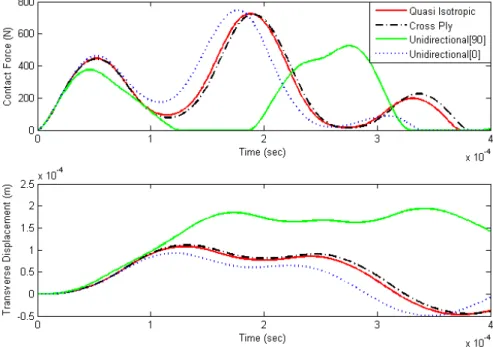
3.2.4 Effect of layup (Stacking Sequence)
To show the dependency of the beam to stacking sequence, four types of layup are investigated here with the presence of 7 percent nanoclay. The number of layers was taken to 24 (see Table 6 for details).
[0 / 45 / 90 / 45 ]
3 3 3 3s
24 layers Quasi Isotropic
[0 / 90 ] 3 3 2s
24 layers Cross Ply
[90 ]
24
24 layers Unidirectional[90]
[0 ]
24
24 layers Unidirectional[0]
Table 6: Four layups that is investigated in this study.
Figure 7 shows the force-time and displacement-time graph of the beam. It can be figured out that the layup along the length of the beam (0 degree layer) has the greatest effect on low-velocity im-pact response of the beam. The reason is related to the high length-to-width ratio of the beam (L>10b). This implies that the layup along the width of the beam is of little significance and the layup along the length plays the key role. It can also be seen in Figure 7 that the beam with the layup of [0] has the maximum force and minimum deflection values, while the beam with the layup of [90] has the minimum force and maximum deflection values. Furthermore, it is obvious from Figure 7 that Quasi isotropic, cross ply, and even unidirectional layer of zero degree has very little difference. It can be said that, if the number of 0-degree layers of the two beams are roughly equal, low-velocity impact response of those beams will be independent of layup and have the same behav-ior.
Latin A m erican Journal of Solids and Structures 12 (2015) 333-354
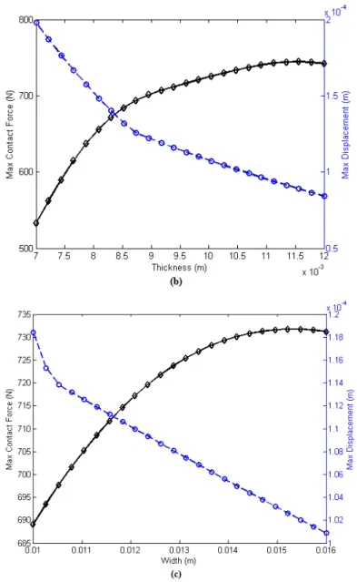
3.2.5 Effect of geometric parameters of the beam on impact response
To investigate the effect of geometrical parameters (i.e., length, width and thickness of the beam),by considering the data in Table 1, the range of variations for length, thickness, and width are 80-160 mm, 7-12 mm, and 10-16 mm, respectively. As it can be seen from Figure 8, the increase in beam length will reduce maximum contact force, while width and thickness of the beam has the reverse effect on maximum contact force. This can be explained by the following relation (Abrate, 1998):
max bs p
F V K M (20)
Where V , Kbs and Mp are impact velocity, target stiffness and mass of the pro‘ectile, respec-tively. On the other hand, the stiffness of a beam with a rectangular cross section is proportional to
3
3 3
EI Ebh
L 12L .Therefore, by taking the two aforementioned relations into consideration, it can be
found that a decrease in length and increase in width and thickness increases the stiffness of the beam, which leads to the increase of maximum contact force. According to Figure 8, the force
gra-dient with respect to length and thic’ness is larger than the width. The reason is that L and h in
3
3 3
EI Ebh
Latin A m erican Journal of Solids and Structures 12 (2015) 333-354
Figure 8: Variation of maximum force and deflection versus geometrical dimensions of the beam: (a) Length, (b) Thickness and (c) Width.
justi-Latin A m erican Journal of Solids and Structures 12 (2015) 333-354 fied such that the increase in thickness will first increase the required force to deform the beam. After that, as the force increases, this is the indentation which mainly occurs instead of deflection and deformation, and thus the force becomes constant (Abrate, 1998).
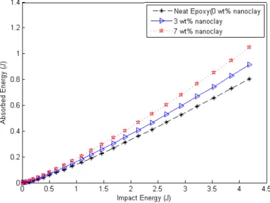
3.2.6 Effect of nanoclay on beam energy absorption
Energy absorption is one of the crucial issues in the structures under impact load. Energy absorp-tion is defined as the difference between the energy of the projectile before and after impact.
2 2
0
1
( )
2 p fi
Absorbed Energy of Beam M V V (21)
Where, V0 andVfi are the initial velocity and after impact velocity of the projectile, respectively.
Note that Vfi can be obtained by solving equation 6 by using Runge-Kutta fourth order technique. In this section, the effect of adding nanoclay on the energy absorption of the structure is investigat-ed. A beam with the thickness of 8 mm and three different weight percentages of nanoclay, namely 0, 3 and 7under different impact energies are studied here. Other required parameters are taken from Table 1. Figure 9 depicts the energy absorbed by the beam versus initial impact energy. It can be seen that in small values (low level) of energy, no considerable change is observed and three specimens roughly show the same behavior. As the impact energy increases, the change in
speci-mens behavior is clearer and the effect of adding nanoparticles becomes more outstanding.
Latin A m erican Journal of Solids and Structures 12 (2015) 333-354
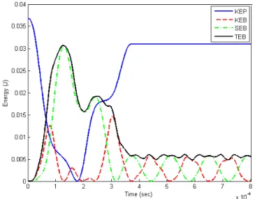
3.2.7 Investigation of energy variations with respect to time
Consider a beam with the properties given in Table 2. According to Ritz s relation for the beam
deflection, kinetic energy of a nanocomposite beam with clamped edges at both ends is expressed as follows:
0
1 1
1 2 3 2
( (w( , )) dx) ( [W ( )] )
2 4
N N
L
beam j
j j
KEB M x t bL t (22)
And strain energy of the beam under pure bending is:
2 2
11 0
1 11
( dx) 16
2
N
L j
j
W j M
SEB bD L
bD L (23)
Total energy of a beam is equal to the summation of strain and kinetic energies:
TEB KEB SEB (24)
Kinetic energy of the projectile is as follows:
2
1
2 p
KEP M V (25)
Variation of kinetic energy of the projectile as well as kinetic energy, strain energy and total energy of the beam is presented in Figure 10. As it can be seen from this figure, the difference between impact energies of the projectile before and after impact is equal to the total energy of the beam, which is based on the conservation of energy. When the contact ceases, the summation of kinetic and strain energies of the beam is constant. This reveals that transformation of energy from strain to kinetic energy occurs when the contact ceases.
Latin A m erican Journal of Solids and Structures 12 (2015) 333-354
4 CONCLUSIONS
The low-velocity impact analysis of a nanocomposite beam was investigated using Hertz s law and MROM. The boundary conditions were taken as clamped-clamped and the impact took place at the center of the beam. The beam was made of glass/epoxy doped with nanoclay and MWCNT. Since the nanoparticles disperse through the matrix, the bonds are created between the nanoparticles and matrix .We have therefore taken the equivalent properties of the matrix and nanoparticles set – obtained from experimental studies in Tables 3 and 5– as an independent variable. After that, this equivalent property was used in MROM to approximate the mechanical properties of the whole nanocomposite. The equations of motion for a nanocomposite beam were proposed using
Euler-Bernoulli beam theory and Hertz s law. Afterwards, the procured set of nonlinear equations, which
were obtained from the equation of motion and Ritz s variational method, was solved using the
Runge-Kutta fourth order method.
Assuming equivalent properties by using MROM is expected to give satisfactory results on low ve-locity impact response, since the effect of nanoparticles has been observed in experimental studies. It was also shown that the analytical model predicts smaller values of contact force in comparison with the FEM. However, the prediction procedure and the behavior of the graph is the same in both cases (analytical and FEM model).
It was concluded that at lower impact energies, the influence of nanoclay is negligible in energy absorption. However, this effect is more noticeable at higher impact energies. Furthermore, by add-ing nanoparticles to the matrix, the maximum contact force increased duradd-ing impact loadadd-ing. It was also concluded that the layup along the length of the beam (zero degree) had the greatest effect on the performance of the beam under impact load. Increase in beam length decreased maximum con-tact force during impact whereas increase in width and thickness of the beam, which leads to the increase of bending stiffness of the beam, increased contact force. The effect of initial velocity on the force and displacement history of the beam center was another parameter that was investigated.
References
Abrate, S. (1998). Impact on composite structures. Cambridge University Press;.
Chan, M.-l., Lau, K.-t., Wong, T.-t., Ho, M.-p. and Hui, D. (2011). Mechanism of reinforcement in a nanoclay/polyme composite. Composites: Part B, 42, 1708–1712.
Gustin, J., Freeman, B., Stone, J., Mahinfalah, M. and Salehi-Khojin, A. (2005). Low-velocity impact of nanocompo-site and polymer plates. Journal of Applied Polymer Science, 96, 2309-2315.
Heshmati, M. and Yas, M. H. (2013). Dynamic analysis of functionally graded multi-walled carbon nanotube-polystyrene nanocomposite beams subjected to multi-moving loads. Materials and Design, 49, 894-904.
Hosur, M. V., Chowdhury, F. and Jeelani, S. (2007). Low-Velocity Impact Response and Ultrasonic NDE of Woven Carbon/ Epoxy Nanoclay Nanocomposites. Journal of Composite Materials, 41, 2195-2212.
Iijima, S. (1991). Helical microtubules of graphitic carbon. Nature, 354, 56-58. Kaw, A. K. (2006). Mechanics of Composite Materials Taylor & Francis Group.
Latin A m erican Journal of Solids and Structures 12 (2015) 333-354
Kojima, Y., Usuki, A., Kawasumi, M., Okada, A., Kurauchi, T. and Kamigaito, O. (1993). Synthesis of nylon 6-clay hybrid by montmorillon it e intercalated with E-caprolactam. Polymer Science, P art A: Polymer Chemistry, 31, 983-986.
Kollár, L. P. and Springer, G. S. (2003). Mechanics of composite structures. Cambridge University Press.
Lam, K. Y. and Sathiyamoorthy, T. S. (1999). Response of composite beam under low velocity impact of multiple masses Composite Structures, 44, 205-220.
Lin, J.-C., Chang, L. C., Nien, M. H. and Ho, H. L. (2006). Mechanical behavior of various nanoparticle filled com-posites at low-velocity impact. Composite Structures, 74, 30-36.
Montazeri, A., Javadpour, J., Alireza Khavandi, Tcharkhtchi, A. and Mohajeri, A. (2010). Mechanical properties of multi-walled carbon nanotube/epoxy composites. Materials and Design, 31, 4202–4208.
Ramakrishnan, K. R., Guérard, S., Viot, P. and Shankar, K. (2014). Effect of block copolymer nano-reinforcements on the low velocity impact response of sandwich structures. Composite Structures, 110, 174-182.
Reis, P. N. B., Ferreira, J. A. M., Zhang, Z. Y., Benameur, T. and Richardson, M. O. W. (2013). Impact response of Kevlar composites with nanoclay enhanced epoxy matrix. Composites Part B: Engineering, 46, 7-14.
Saber-Samandari, S. and Afaghi-Khatibi, A. (2007). Evaluation of elastic modulus of polymer matrix nanocompo-sites. Polymer Composites, 28, 405-411.
Saber-Samandari, S. and Khatibi, A. A. (2006). The effect of interphase on the elastic modulus of polymer based nanocomposites Key Engineering Materials, 312.
Saber-Samandari, S., Khatibi, A. A. and Basic, D. (2007). An experimental study on clay/epoxy nanocomposites produced in a centrifuge. Composites Part B: Engineering, 38, 102-107.
Taraghi, I., Fereidoon, A. and Taheri-Behrooz, F. (2014). Low-velocity impact response of woven Kevlar/epoxy laminated composites reinforced with multi-walled carbon nanotubes at ambient and low temperatures. Materials and Design, 53, 152-158.
Utracki, L. (2004). Clay-containing polymeric nanocomposites,Rapra Technol 2004;1.
Vodenitcharova, T. and Zhang, L. C. (2006). Bending and local buckling of a nanocomposite beam reinforced by a single-walled carbon nanotube. International Journal of Solids and Structures, 43, 3006-3024.
Wuite, J. and Adali, S. (2005). Deflection and stress behaviour of nanocomposite reinforced beams using a multiscale analysis. Composite Structures, 71, 388-396.
Xu, Y. and Hoa, S. V. (2008). Mechanical properties of carbon fiber reinforced epoxy/clay nanocomposites. Compo-sites Science and Technology, 68, 854-861.
Yas, M. H. and Heshmati, M. (2012). Dynamic analysis of functionally graded nanocomposite beams reinforced by randomly oriented carbon nanotube under the action of moving load. Applied Mathematical Modelling, 36, 1371-1394.
Yas, M. H. and Samadi, N. (2012). Free vibrations and buckling analysis of carbon nanotube-reinforced composite Timoshenko beams on elastic foundation. International Journal of Pressure Vessels and Piping, 98, 119-128.
Yasmin, A., Abot, J. L. and Daniel, I. M. (2003). Processing of clay/epoxy nanocomposites by shear mixing. Scripta Materialia, 49, 81-86.