Georgios Karanikoloudis
Canterbury Cathedral –
Structural Analysis of the
South Aisle
Canterbur
y Cat
hedr
al – Str
uctur
al Anal
ysis of t
he Sout
Georgios Karanikoloudis
| 2014 Czech university of PragueCanterbury Cathedral –
Structural Analysis of the
South Aisle
DECLARATION
Name: Georgios Karanikoloudis Email: Karanikoloudis@hotmail.com
Title of the Msc Dissertation:
Canterbury Cathedral – Structural Analysis of the South Aisle
Supervisor(s): Paulo B. Lourenco (University of Minho) Claudio Corallo (The Morton Partnership Ltd)
Year: 2013-2014
I hereby declare that all information in this document has been obtained and presented in accordance with academic rules and ethical conduct. I also declare that, as required by these rules and conduct, I have fully cited and referenced all material and results that are not original to this work.
I hereby declare that the MSc Consortium responsible for the Advanced Masters in Structural Analysis of Monuments and Historical Constructions is allowed to store and make available electronically the present MSc Dissertation.
University: University of Minho
Date: 10/09/2014
Signature:
ACKNOWLEDGEMENTS
I would like to express my gratitude to the Dean and Chapter of Canterbury Cathedral for financing this Thesis. Special thanks to the Surveyor of the Fabric Jonathan Deeming for the provided information. This thesis had for me a realistic and practical involvement which wouldn’t have been possible without the technical support and assistance provided by the Morton Partnership Ltd, for which I’m grateful and in particular to Claudio Corallo for his valuable guidance.
My deepest acknowledgements to my thesis supervisor, Prof. Paulo B. Lourenco for his commitment, advice and help. His guidance and involvement during my dissertation, in spite his heavy schedule, has given the chance to enrich my technical knowledge and for that I’m grateful.
Throughout this thesis, the PhD Researcher Nuno Mendes has offered an amazing help and assistance in the ambiental vibration tests and the numerical modelling, to whom I would like to express my sincere thanks.
My outmost acknowledgements to the S.A.H.C Consortium, for the scholarship I received that complimented greatly my efforts and studies on the structural analysis of historic constructions. Lastly, I would like to thank all my friends and colleagues, whom I bothered with queries, during this hard, long effort.
ABSTRACT
The Canterbury Cathedral at Canterbury Kent, in the UK, seat of the Archbishop of Canterbury, head of the Anglican Church, stands as a monument of English Gothic architecture of immense importance, and is part of the UNESCO World Heritage site. Its central nave and lateral aisles, secluded by the twin bell towers of the west front and the west transept, with a 72 m tower at the crossing, is a fine example of the English Gothic style of the early 14th century.
The inspection and damage survey, conducted in the Cathedral’s nave, revealed the generally good condition of the skeleton, with the exception of a repetitive crack pattern on the vault’s intrados, which intensified in a part of the south aisle, including some outward rotating movement and cracking in the south flying buttresses. Ambient vibration tests were carried out at the nave and south aisle roof level, in order to identify the modal response of the structure.
A Graphic Statics analysis was conducted ,with the aim to compliment the results of the structural analysis, by investigating the load paths in the structural elements and how the geometrical configuration of the Cathedral’s nave section advocated its structural performance.
Through the geometrical survey, a 3D CAD model of a typical transversal section of the nave was elaborated and, accordingly, a FE model was built in Midas FX+ for DIANA software, in order to investigate various hypothesis of structural damage, by reproducing the existing crack pattern and obtaining certain levels of structural safety. The results from the ambient vibrations tests were used for the calibration of the FE model. Different nonlinear static analyses under dead loading were performed, by considering model variables, such as the infill volume, the presence of lateral thrust from the nave’s roof and differential settlements. A validated FE model, having a sufficient correlation with the existing damage was used to determine to safety factor of the structure in both lateral and vertical loading.
RESUMO
A Catedral de Canterbury localizada no condado de Canterbury, Reino Unido, sede do arcebispo de Canterbury, chefe da Igreja Anglicana, é um monumento de enorme importância para a arquitetura gótica inglesa, sendo parte do Património Mundial da UNESCO. A sua nave central e corredores laterais, abrigados pelas torres da fachada oeste e do transepto oeste, é um belo exemplo do estilo gótico Inglês do início do século 14.
A inspeção e pesquisa de danos, realizadas na nave da Catedral, revelaram um bom estado geral do esqueleto, exceto um padrão de fendilhação que se repete no intradós da abóbada, intensificando-se no corredor sul, incluindo movimento de rotação no sentido exterior e fendas nos arcos dos contrafortes localizados a sul. Foram realizados ensaios de vibração ambiental na nave e no corredor sul ao nível da cobertura, a fim de identificar a resposta modal da estrutura.
Uma análise gráfica estática, complementa os resultados da análise estrutural, investigando a distribuição de carga nos elementos estruturais e em que forma a configuração geométrica da seção da nave da Catedral afeta o desempenho estrutural da mesma.
Através do levantamento geométrico, um modelo 3D CAD de uma seção transversal típica da nave foi elaborado um modelo de elementos finitos, construído em Midas FX + para o software DIANA, a fim de investigar várias hipóteses de danos estruturais, reproduzindo o padrão de fendilhação existente e obtendo os níveis de segurança estrutural. Os resultados dos ensaios de vibração ambiental foram utilizadas para a calibração do modelo de elementos finitos. Foram realizadas analises estáticas não-lineares com cargas permanentes, considerando-se as variáveis do modelo, tais como o volume de enchimento, a presença do impulso lateral da cobertura da nave e assentamentos diferenciais. Um modelo de elementos finitos validado, tendo uma correlação suficiente com os danos existentes, foi utilizado para determinar o fator de segurança da estrutura para carregamentos laterais e verticais.
ΠΕΡΙΛΗΨΗ
Ο Καθεδρικός ναός του Canterbury, στην πόλη του Canterbury της επαρχίας Kent, της Μεγάλης Βρετανίας, αποτελεί την έδρα του Αρχιεπισκόπου του Canterbury, κεφαλή της Αγγλικανικής Εκκλησίας. Δεσπόζει ως μνημείο Αγγλικής Γοτθικής αρχιτεκτονικής εξαιρετικής σπουδαιότητας και ανήκει στον κατάλογο των Μνημείων Παγκόσμιας Κληρονομιάς της UNESCO. Το κεντρικό και τα δύο πλευρικά του κλίτη περιέχονται μεταξύ των δύο δίδυμων πύργων της δυτικής πρόσοψης και του δυτικού εγκάρσιου κλίτους, με τον κεντρικό πύργο ύψους 72 μέτρων, και αποτελούν ένα χαρακτηριστικό παράδειγμα του Αγγλικού Γοτθικού στυλ των αρχών του 14ου αιώνα. Η επί τόπου έρευνα και μελέτη της παθολογίας, που επικεντρώθηκε στο κεντρικό και πλευρικά κλίτη του ναού, αποφάνθηκε την γενικά καλή κατάσταση του στατικού συστήματος, πέραν μιας αλληλουχίας ρωγμών στο εσωράχιο των θόλων, που εντείνεται σε τμήμα του νότιου πλευρικού κλίτους, περιλαμβανομένης και μιας έξω περιστροφικής κίνησης, με συνεπάγοντες ρωγμές στις νότιες τοξωτές αντηρίδες. Η επιτόπια εκτέλεση ambient vibration tests, στο επίπεδο της στέγης του κεντρικού και του νότιου κλίτους, προσδιόρισαν την ιδιομορφική απόκριση της κατασκευής. Η γραφική στατική ανάλυση της κατασκευής πραγματοποιήθηκε ώστε να απότελέσει ένα ακόμη κριτήριο σύγκρισης με τα αποτελέσματα της στατικής ανάλυσης, μέσω της διερεύνησης των διαδρομών των φορτίων στα στατικά μέλη και του βαθμού επιρροής της γεωμετρικής διάρθρωσης του ναού στη στατική συμπεριφορά του. Μέσω της αρχιτεκτονικής αποτύπωσης, παράχθηκε μια τρισδιάστατη γεωμετρική απεικόνιση μιας τυπικής κάθετης τομής του κεντρικού και πλευρικών κλιτών και μέσω αυτής ένα αριθμητικό προσομοίωμα, μέσω του προγράμματος πεπερασμένων στοιχείων Midas FX+ for DIANA, προκειμένου να διερευνηθούν πιθανές αιτίες δομικής βλάβης. Βασικό κριτήριο αποτέλεσε η αναπαραγωγή του υπάρχοντος μοτίβου ρωγμών και ο καθορισμός επιπέδων δομικής ασφάλειας. Μη γραμμικές στατικές αναλύσεις πραγματοποιήθηκαν, υπό την επιρροή μόνιμων φορτίων και μεταβλητών συσχέτισης, όπως ο όγκος πλήρωσης των θόλων, η παρουσία πλευρικής ώσης μέσω της στέγης και η ύπαρξη διαφορικών καθιζήσεων. Το τελικό παραγόμενο αριθμητικό προσομοίωμα της τυπικής τομής του ναού, έχοντας επαρκή συσχέτιση με την υφιστάμενη βλάβη, χρησιμοποιήθηκε για να προσδιοριστεί ο συντελεστής δομικής ασφαλείας τόσο σε πλευρική και κατακόρυφη ώθηση.
TABLE OF CONTENTS
1. INTRODUCTION ... 1
2.
HISTORIC SURVEY ... 3
2.1
The Gothic Cathedrals: Design and Form – The English Gothic ... 3
2.1.1 Introduction ... 3
2.1.2 Gothic Cathedral – Plan arrangement ... 3
2.1.3 Decisive features of Gothic architecture ... 4
2.1.4 Other architectural – decorative features ... 12
2.1.5 The English Gothic ... 12
2.1.5.1 Distinctive characteristics ... 12
2.1.5.2 Pointed ribbed cross vault variables ... 13
2.1.6 Use of materials ... 16
2.1.7 Gothic Revival of 19
th– 20
thcentury ... 16
2.2
Damage in Gothic Cathedrals ... 17
2.2.1 Introduction ... 17
2.2.2 Large deformations ... 17
2.2.3 Cracks under tensile failure ... 17
2.2.4 Cracks under compressive failure ... 18
2.2.5 Material deterioration ... 18
2.2.6 Other parameters related to damage in Gothic Cathedrals ... 19
2.2.6.1 Construction process ... 19
2.2.6.2 Additions – alterations ... 20
2.2.6.3 Accidental loading ... 21
2.2.7 Specified damage in structural elements ... 22
2.2.7.1 Cracks in Gothic cross-vaults ... 22
2.2.7.1.1 Compatibility cracks ... 22
2.2.7.1.2 Cracks from lateral instability ... 22
2.2.7.2 Collapse mechanisms of macroelements ... 23
2.3
History of Canterbury Cathedral ... 24
2.3.1 Introduction ... 24
2.3.3 The Church of Archbishop Lanfranc ... 26
2.3.4 The new Choir of Archbishop Anselm (1096-1130) ... 27
2.3.5 The New Cathedral (1175 -1184) ... 28
2.3.6 14
th– 19
thCenturies ... 29
2.3.7 20
thcentury’s intervention & conservation works ... 30
2.3.7.1 1946 - 1968 ... 30
2.3.7.2 1968 - 1991 ... 31
2.3.7.3 1991 - 2013 ... 31
2.3.7.4 2013 - present ... 33
3. GEOMETRICAL SURVEY ... 34
3.1
Introduction ... 34
3.2
Nave configuration ... 36
3.3
Lateral aisles configuration ... 37
3.4
Vertical abutments ... 39
3.5
Roof trusses in nave and lateral aisles ... 39
3.6
System of ties ... 41
3.7
Infill ... 42
3.8
Flying buttresses ... 43
4.
INSPECTION AND INVESTIGATION SURVEY ... 44
4.1
Visual inspection plan ... 44
4.2
Damage survey in nave and aisles vaults ... 45
4.2.1 Crack pattern ... 47
4.2.2 Deterioration of plaster ... 49
4.3
Damage survey in flying buttresses of south aisle ... 50
4.3.1 Joint failure ... 53
4.3.2 Crust formation ... 53
4.3.3 Biological growth ... 54
4.4
Outward tilting of the vertical elements ... 55
4.5
Material properties ... 56
4.5.1 Caen limestone masonry... 58
4.5.2 Infill material properties ... 60
4.5.4 Softening behavior and fracture energy ... 61
4.5.3 Implemented material properties ... 63
5.
DYNAMIC IDENTIFICATION TESTS ... 64
5.1
Introduction ... 64
5.2
Test preparation and setup ... 64
5.3
Experimental results ... 67
6.
GRAPHIC STATICS – LINE OF THRUST ... 71
6.1
Stability of Gothic arches ... 71
6.2
Stability of flying buttresses ... 72
6.3
Stability of Gothic quadripartite cross vaults... 73
6.4
Pseudo 3D thrust analysis with the sliding technique ... 73
6.5
Line of thrust in a typical bay section ... 75
6.6
Level of stresses ... 77
7.
FE ANALYSIS ... 78
7.1
FE model generation ... 78
7.2
Inelastic behavior ... 80
7.3
FE model update ... 81
7.4
Simulations ... 84
7.5
Conclusions ... 104
8.
CONCLUSIONS OF THE THESIS ... 107
List of Figures
Figure 2-1. Gothic Cathedral's schematic plan (left) and cross section (right) ("Gothic
Architecture" 2014b). ... 4
Figure 2-2. Transverse 3D representation based on Exeter Cathedral. Main architectural
parts ("Nevertopia" 2014). ... 5
Figure 2-3. Different kinds of pointed arches in Gothic architecture ("Gothic Arches" 2014). .. 6
Figure 2-4. (Left) York Minster Cathedral, England, York (1338-1408). Equilateral arches at
the east front ("York Minster" 2014). (Right) Gloucester Cathedral, England (1089–1499).
Depressed arches at the east front ("Gloucester Cathedral" 2014). ... 6
Figure 2-5. Representation of the construction process of a pointed ribbed cross-vault, by
means of centering (Climent 2014). ... 7
Figure 2-6. (Left) In the appearing typical section of a Gothic Cathedral, the upper flying
buttress receives the lateral thrust from the weight of the roof, the wind and the weight of the
clerestory wall, whereas the lower one counteracts the lateral outward forces from the weight
of the nave vaults. Many possible thrust lines are shown (Luca et al. 2014). (Middle) Villard
de Honnecourt’s drawing of the flying buttresses system at Reims Cathedral ("Reims
Cathedral" 2014). (Right) Exterior view of the east front of Reims Cathedral at Reims, France
(1211-1275). System of flying buttresses ("Reims Cathedral" 2014). ... 7
Figure 2-7. Inside view of La Sainte-Chappelle in Paris, France. 1239-1248. Stained glass
windows of enormous size cover all the facades, reducing the stone framework to the
minimum ("Sainte-Chappelle" 2014). ... 8
Figure 2-8. Salisbury Cathedral (1220-1258). The spire in the tower of the crossing is the
tallest in United Kingdom (123 m in height) ("Salisbury Cathedral" 2014)... 9
Figure 2-9. Milan Cathedral. Advanced use of pinnacles and spires in the vertical
arrangement of piers, buttresses and roof gables ("Milan Cathedral" 2014). ... 9
Figure 2-10. (Left) Notre Dame Cathedral, Reims, France (1211). (Right) York Minster
Cathedral, York, United Kingdom (1250). Typical arrangement of a Gothic Cathedral’s
Majesty in France and England ("Gothic Architecture" 2014a). ... 9
Figure 2-11. Configuration of two main timber roof trusses; King post (Left) and Queen post
(Right) and their structural components ("Timber Roof Truss" 2014). ... 10
Figure 2-12. Connection of the timber trusses to form the structural roof system ("Timber
Roof Truss" 2014). ... 11
Figure 2-13. Nave section, Cathedral of Notre-Dame de Reims, Reims, France (1211-1417).
Timber roof truss configuration ("Cathedral of Notre-Dame" 2014)... 11
Figure 2-14. Complex timber roof structure of Soissons Cathedral in Soissons, France
(1180-1479). Photo from reconstruction during the 18th century ("Gothic Cathedral and Church
Construction" 2014). ... 11
Figure 2-15. (Left) View of the central nave of the Canterbury Cathedral (1070-1834) in the
UK. The pier molds are incorporated with the arch molds, resulting in a vertical continuity,
thus creating a series of tree-like patterns ("Canterbury Cathedral" 2007). (Right) Pier section
in the nave (center section), additional portion of the pier next to tower (left section) and arch
mold (right section) (Willis 1845). ... 12
Figure 2-16. (Left) East end in York Minster Cathedral, showing the typical square
configuration ("York Minster" 2014). (Right) East end of Canterbury Cathedral, having a
semi-circular plan with three chapels ("Canterbury Cathedral" 2014). ... 13
Figure 2-17. (Left) Quadripartite pointed crossed-ribbed vault with transverse, diagonal and
wall ribs, with no ridge ribs ("Medieval Construction" 2014). (Right) Durham Cathedral,
England (1093-1133), Romanesque Style ("Durham Cathedral" 2014). ... 13
Figure 2-18. (Left, middle) Quadripartite pointed crossed-ribbed vault with ridge ribs
("Medieval Construction" 2014). (Right) St. Albans Cathedral, England (1077-1893),
Romanesque/Gothic Style ("St. Albans Cathedral" 2014). ... 14
Figure 2-19. (Left, middle) Tierceron vault. Consists of additional secondary diagonal ribs,
called tiercerons, extended from the springers to the transverse ridge ribs ("Medieval
Construction" 2014). (Right) Exeter Cathedral, England (1112-1400), Norman/Gothic Style
("Exeter Cathedral" 2014). ... 14
Figure 2-20. (Left, middle) Lierne vault. The main and secondary diagonal ribs intersect in
nodes around the boss perimeter and additional tertiary ribs span between those nodes and
the boss. In more complicated connections between liernes Stellar vaults are produced
("Medieval Construction" 2014). (Right) Ely Cathedral, England (1083-1375), Romanesque
/Gothic Style ("Ely Cathedral" 2014). ... 15
Figure 2-21. (Left, middle) Fan vault. Many ribs, having the same curvature, extend from the
springers, thus forming fan-conical shaped vaults. Flat central spandrels fill the voids.
Depending on the type of bay (square or rectangular) the shape of the central spandrel
changes. In a more complex design, these vaults were combined with lierne ribs ("Medieval
Construction" 2014). (Right) Canterbury Cathedral, England (1070-1834), Romanesque
/Gothic Style. Fan square vault at the tower in the crossing ("Canterbury Cathedral" 2014). 15
Figure 2-22. (Right) Notre Dame in Paris (1163-1345). From 1845-1870 the monument
undertook a controversial restoration, resulting in many additions and reconstructions, such
as the chimeras that were extracted from other Gothic buildings (Left) ("Notre Dame de
Paris" 2014). ... 16
Figure 2-23. Deformation patterns in a transverse section of Mallorca Cathedral. Chromatic
scale distribution of normal stresses. The white color represents cracking. (Left) Deformation
under dead load. (Right) Deformation under seismic loads (Roca et al. 2005). ... 17
Figure 2-24. Pier of Tarazona Cathedral. Under excessive compressive stresses stone
crushing and detachment occurred (Roca et al. 2005) ... 18
Figure 2-25. In 1984 a great fire, believed to have been caused by a lighting strike, destroyed
the timber roof of the south transept of York Minster. Additional damage was caused by the
vast quantities of water used to put out the fire. ("An Introduction to the History of York"
2014) ... 19
Figure 2-26. (Left) Typical cross-section of a Gothic Cathedral at an intermediate
construction stage, prior to the construction of the nave’s vault. Arrows showing the
counteracting lateral forces. (Right-up) Construction phase involving the erection of piers and
buttresses and the centering of flying buttresses. (Right-down) Sketch showing the system of
timber trusses. The nave’s vault is not yet constructed ("Index of /URBS110/Gothic" 2014). 20
Figure 2-27. (Left) Chronological construction phases hypothesis and additions in elevation
of the central crossing tower in Wells Cathedral in UK (1176-1490). Settlements and
foundation failure have occurred. (Right) FEM model of the tower showing westward leaning
(D'Ayala et al. 2003). ... 21
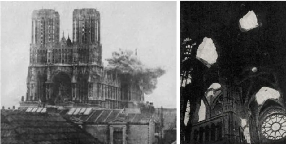
Figure 2-28. Reims Cathedral, Reims, France. (Left) Picture at the time of struck from
German shellfire in September 1914. (Right) Inside view. Holes in the vault system from the
bombarding (Theodossopoulos et al. 2008). ... 21
Figure 2-29. Typical crack patterns for masonry vaults. (a) Cracks running parallel with the
side walls (Sabouret’s cracks). (b) Typical pathologies for some common vaults (Roca 2014).
... 22
Figure 2-30. Crack pattern in Gothic vaults under outward movement of the supports. (Left)
Outward movement of all supports. (Right) Relative movement of middle abutments. Hinges
form in the area of springing and in the proximity of the crown. Higher compressive stresses
concentrate near the supports (Theodossopoulos 2008). ... 23
Figure 2-31. (Left) Kinematic failure mechanisms applied on the facade of Santa Maria del
Mar, Barcelona, Spain (1329-1383) (Roca et al. 2010). (Right) Photo revealing fragmentation
cracks due to uneven settlements and the tower’s rotation (Roca 2014). ... 23
Figure 2-32. (Left) Aerial view of Canterbury Cathedral from southeast ("Canterbury
Cathedral Aerial" 2013). (Right) Northwest view of Canterbury Cathedral ("Britain’s Greatest
Cathedrals" 2012). ... 24
Figure 2-33. (Above left) Photo taken from the nave’s ceiling, showing the western apse
foundation of the Saxon Cathedral ("Canterbury Cathedral" 2008). (Above right) Imaginary
representation of the Anglo-Saxon Cathedral, as believed during the final phase IV (1025),
comprised by the Cathedral and many additional buildings ("AD 1000 - Canterbury
Cathedral" 2007). (Below) Plan of the Anglo-Saxon Cathedral showing parts from the four
different phases, as identified from the archaeological excavation in 1993 ("Canterbury
Cathedral" 2008). ... 26
Figure 2-34. (Left) Ground plan of Lanfranc’s Canterbury Cathedral (1070-1077). The exact
form of the apses is uncertain, as only remains of their foundations were uncovered. The
plan and proportions were based on Lanfranc’s abbey in Normandy (Dudley 2010). (Right)
Imaginary representation of Canterbury's Norman Cathedral under Archbishop Lanfranc
(1077), comprised by the Cathedral and many additional buildings ("Canterbury Cathedral"
2007). ... 27
Figure 2-35. Plan of Canterbury Cathedral in 1174. The lighter shading pattern in the
crossing of the new Choir is the intersecting termination of Lanfranc’s Cathedral on the
eastern front (Willis 1845). ... 27
Figure 2-36. (Left) Ground plans of Canterbury Cathedral as it evolved over time, from 1070
to 1175. (a) The Cathedral of Lanfranc, (b) the Cathedral of Anselm, (c) the Cathedral of
William of Sens ("Canterbury Cathedral" 2007).(Right) Transverse section of the choir. In the
left cross section the new Gothic Choir after the reconstruction is presented. In the right part
of the cross section Archbishop Anselm’s Choir before the fire is depicted. (Willis 1845). .... 28
Figure 2-37.(Above) Geometrical representation of Canterbury Cathedral’s west front in
different time phases (Dudley 2010): (a) The geometry of Lanfranc’s west front 1070-1077,
(b) Prior’s Thomas Chillenden west front completed in 1401, (c) Completion of southwest
tower in 1459, (d) First construction phase of central tower (1470-1490) after demolition in
1430. Architects: R. Beck & J. Wastell, (e) Second construction phase of central tower
completed in 1504 by J. Wastell, (f) Aspect of the west front as it exists in present time.
(Below left) The west front aspect of Canterbury Cathedral in 1821 before the completion of
the north-west tower ("Canterbury Cathedral" 2014). (Below right) West front configuration of
Canterbury Cathedral at present time ("Canterbury Cathedral" 2005). ... 30
Figure 2-38.View of the interior nave roof void, depicting the concrete infill layer and the
drilled hole for drainage. ... 32
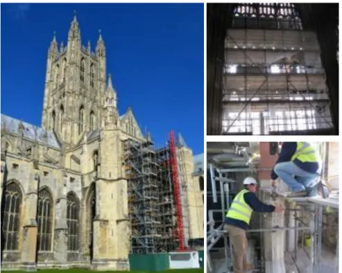
Figure 2-39. (Left) The Great South Window of the South West Transept behind scaffolding.
(Right above) Inside view of the Great South Window tracery of the South West Transept.
The glass panels have been removed and stone parts are been taken off piece by piece.
(Right below) Process of removal of damaged stone masonry in the Great South Window
tracery of the South West Transept which will later be replaced by replicas. View of the
tracery at top level. ("The Great South Window" 2014). ... 33
Figure 3-1. (Left) Top plan of Canterbury Cathedral depicting the nave and lateral aisles
area, as well as the case study area of the critical cross sections. (Right) Transverse cross
section of the nave and lateral aisles of Canterbury Cathedral looking west (Morton
Partnership Ltd). ... 34
Figure 3-2. Longitudinal cross section and top plan of the nave, transepts and choir of
Canterbury Cathedral (Willis 1845). ... 34
Figure 3-3. Top plan of the vertical abutments and vault configuration of the critical area of
the nave, depicting dimensions (meters) based on the historic survey, the in situ inspection
and the geometrical survey provided by Morton Partnership Ltd. ... 35
Figure 3-4. Generated geometrical model of the critical transvers cross section of Canterbury
Cathedral’s nave and the adjoining part of the cloister. ... 35
Figure 3-5. Generated geometrical model of the nave of Canterbury Cathedral and the
adjoining part of the cloister. ... 36
Figure 3-6. (Left) View of the nave of Canterbury Cathedral looking east. (Right) View of the
Gothic lierne quadripartite cross vaults of the nave of Canterbury Cathedral (Photographic
survey). ... 37
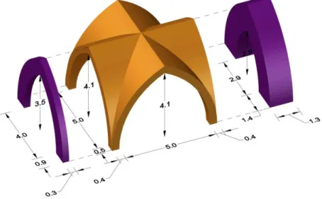
Figure 3-7. Gothic cross vault configuration and dimensions (meters) in the nave of
Canterbury Cathedral and adjacent clerestory arches, as generated for the 3D CAD model.
... 37
Figure 3-8. (Left) View of the north aisle of Canterbury Cathedral looking east. (Right) View
of the south aisle of Canterbury Cathedral looking east (Photographic survey). ... 38
Figure 3-9. Gothic cross vault configuration and dimensions (meters) in the south aisle of
Canterbury Cathedral with the adjacent arcade arch (left) and the aisle window arch (right),
as generated for the 3D CAD model. ... 38
Figure 3-10. Sections depicting the actual and chosen equivalent dimensions (meters) and
area of the piers and buttresses of Canterbury Cathedral (Willis 1845). ... 39
Figure 3-11. Structural parts of the roof framing in the nave of Canterbury Cathedral and
section areas (millimeters). ... 40
Figure 3-12. Structural parts of the roof framing in the south aisle of Canterbury Cathedral
and section areas (millimeters). ... 40
Figure 3-13. View of the roof void in the south aisle looking west (Photographic survey). .... 41
Figure 3-14. (Left) External view of the nave clerestory walls of Canterbury Cathedral,
depicting the two anchor cross shaped plates on the right side of each transverse section
(Morton Partnership Ltd). (Right) Inside view of the roof void in the nave of Canterbury
Cathedral, depicting the iron tie in the clerestory walls above the vaults (Photographic
survey). ... 41
Figure 3-15. (Left) View of the iron tie at mid span (Right) Coupling system at the mid span of
the iron tie (Photographic survey). ... 42
Figure 3-16. (Left) 3D representation of the south 3D CAD model of the critical nave section
of Canterbury Cathedral, depicting the infill volumes. (Middle) Infill and cross vault system at
south aisle roof void. (Right up) Infill and cross vault system at nave roof void. (Right down)
Drilled hole in the exterior wall at the level of concrete layer infill, used for drainage
(Photographic survey). ... 42
Figure 3-17. (Left) East view of flying buttress in the south aisle of Canterbury Cathedral,
depicting dimensions (meters) on the interface between the clerestory wall and vertical
buttress, as well as elevation levels from base. (Right down) View of the south aisle of
Canterbury Cathedral, presenting the system of vertical and flying buttresses (Photographic
survey). ... 43
Figure 4-1. Top plan of Canterbury Cathedral depicting the sections and bays of the nave
and lateral aisles, consisting the case study area (Morton Partnership Ltd). ... 44
Figure 4-2. (Left) View of the nave and lateral aisles of Canterbury Cathedral looking east
("Canterbury Cathedral" 2014). (Right) 3D representation of the vaults intrados in the nave
and lateral aisles of Canterbury Cathedral. ... 45
Figure 4-3. Damage map of the intrados of the vault system in the nave and lateral aisles of
Canterbury Cathedral. ... 46
Figure 4-4. (Left) Amplified deformation of Burgos Cathedral cross section. The springing of
the aisle vault spreads inwards, while the upper part of the nave deforms outwards. (Right)
FEM model representing the large deformation of a vault in St. Francis Basilica under
excessive outward movement, leading to the collapse of the vault, caused by the earthquake
in September 1997 (Theodossopoulos et al. 2008). ... 47
Figure 4-5. Damage map of the case study area, which depicts the current and former
estimated infill boundaries... 48
Figure 4-6. Corner detachment of a vault, provoked by differential settlements and rotations
at base, in the Monastery of Salzedas, Portugal (Lourenço et al. 2008). ... 49
Figure 4-7. Possible magnified displacement field of a medium-end settlement, induced in
the south part of the foundation of Canterbury Cathedral, which affects the vertical abutments
of the south part of the nave and aisle by inducing vertical translations and outward leaning.
... 49
Figure 4-8. (Left) Graphic representation of the nave and lateral aisles of Canterbury
Cathedral. The flying buttresses 2 and 3, for which damage maps were prepared, are
depicted in red. (Right) View of the flying buttresses of the south aisle looking west. ... 50
Figure 4-9. Damage maps of the west and east view of flying buttress 2 at the south aisle of
Canterbury Cathedral. ... 51
Figure 4-10. Damage maps of the west and east view of flying buttress 3 at the south aisle of
Canterbury Cathedral. ... 52
Figure 4-11. Crack patterns of joint failure from west view of flying buttress 2 (Left) and 3
(Right) of the south aisle of Canterbury Cathedral. ... 53
Figure 4-12. Crust formation and flaking in large areas of Caen stone masonry from west
views in the flying buttress 3 of the south aisle of Canterbury Cathedral. ... 54
Figure 4-13. Biological growth in form of algae, mosses and higher plants in the upper
surface of flying buttress 3 (east view) in the south aisle of Canterbury Cathedral. ... 54
Figure 4-14. Cross section 3 depicting the south aisle and half of the nave of Canterbury
Cathedral, prepared by the Downland Partnership Ltd and provided by the Morton
Partnership Ltd. The inclination of the vertical abutments is depicted in red. ... 55
Figure 4-15. Determination of knowledge levels and confidence factors, corresponding to the
extent of material testing and on-site inspections (Franchetti 2014). ... 57
Figure 4-16. Test results from double flat jack tests and sonic pulse velocity, performed in
different stone masonry typologies of Campi Alto di Norcia (Perugia, Italy) (Cardani et al.
2013). ... 57
Figure 4-17.Values of the elastic modulus, obtained by double flat jack tests on different
masonry typologies. The results have been grouped in order to allow a comparison of values
for regular stonework with thin joints, brickwork, and irregular stone masonry (Binda et al.
2007). ... 60
Figure 4-18. Stress - displacement diagrams of quasi-brittle materials under tensile (left) and
compressive (right) loading (Lourenço 1998). ... 61
Figure 4-19. Shear stress - displacement diagram of quasi-brittle materials (Lourenço 1998).
... 62
Figure 4-20. Solid clay brick masonry tests and numerical results are presented in diagrams.
(Left) Uniaxial tension - crack displacement diagram. (Middle) Shear stress - crack
displacement diagram. (Right) Uniaxial compression - crack displacement diagram
(Lourenço 1998). The shaded areas represents the experimental envelope of tests. ... 62
Figure 5-1. Measuring equipment: (a) accelerometer on the intrados springing of the flying
buttresses, (b): accelerometer on the exterior cladding of the nave wall, (c) and (d): data
acquisition equipment. ... 65
Figure 5-2. Disposition of accelerometers in performed Setups of the dynamic identification
tests (Reference sensors depict in red colour). ... 66
Figure 5-3.Data driven with the poles selection through the several test setups of the
Stochastic Subspace Identification method. ... 67
Figure 5-4. Mode shapes obtained from the Setups 1, 3 and 4. ... 68
Figure 5-5. MAC values obtained from the Setups 1, 3 and 4. ... 69
Figure 5-6. Averaged Normalized Power Spectral Density for the vertical accelerometers of
the Setup 2 and 5. ... 70
Figure 5-7. Averaged Normalized Power Spectral Density for the horizontal accelerometers
of the Setup 5. ... 70
Figure 6-1. The minimum and maximum thrust line that defines the boundaries of the stability
of a pointed Gothic arch. The five hinges for the maximum thrust are depicting (Block et al.
2006). ... 71
Figure 6-2. Failure mechanism in a circular arch under spreading of the abutments. The
three hinges of central part of the arch are depicting (Block et al. 2006). ... 71
Figure 6-3. The flying arch in Agnicourt church in France is considered to be in state of
minimum thrust (Block 2005)... 72
Figure 6-4. (Left) Line of thrust in flying buttress of the south aisle of Canterbury Cathedral in
corresponding bay 3. (Right) Damage map of the flying buttress of section 3 with the
documented hinge, which was used as reference to conduct the thrust analysis. ... 72
Figure 6-5. Thrust trajectories in cross vaults in three dimensional (Top row) and plan view
(Bottom row), targeting the springings with different configurations, which are comprised of
(a) parallel and diagonal arches, (b) arches directly from the springings, (c) superposition of
first two patterns, (d) quadrilateral arches in plan, directly from the springings, (e) triangulated
patterns in each quarter of the vault, parallel to the diagonals (Block et al. 2014). ... 73
Figure 6-6. A 3D pseudo thrust analysis applied in a Gothic ribbed cross vault, using the
sliding technique, in order to obtain the line of thrust (Block 2009). ... 74
Figure 6-7. Schematic representation of the resultant thrust in the springing of a Gothic cross
vault. ... 74
Figure 6-8. Cross section of the typical bay in the nave of Canterbury Cathedral depicting the
macroblocks and the points of application with the force vectors of the transversal structural
elements. ... 75
Figure 6-9. Cross section of the typical bay in the nave of Canterbury Cathedral depicting the
line of thrust and the potential hinges, where the thrust line is tangent to the boundaries of
the structural elements. ... 76
Figure 6-10. Stress distribution of a cross section when the resultant force is applied within
its middle third (Pela et al. 2014b). ... 77
Figure 7-1. East view (a) and 3D view (b) of the elaborated FE model of the typical bay in the
nave of Canterbury Cathedral, depicting the FE mesh. ... 78
Figure 7-2. Quality mesh check in relation the aspect ratio of elements. ... 79
Figure 7-3. (Left) View of a TE12L isoparametric solid pyramid element, with three sides and
four nodes. (Right) View of a L2TRU two-node directly integrated (1-point) truss element
(DIANA 2014a). ... 79
Figure 7-4. (Left) Crack stress and strain curve, specifying the tensile behavior of stone
masonry with an exponential softening function, beyond the tensile strength. (Right) Crack
stress and strain curve, specifying the compressive behavior of stone masonry with a
parabolic curve (DIANA 2014b). ... 80
Figure 7-5. (Left) the Modified Newton-Raphson iteration method. (Right) Convergence
under the energy norm (DIANA 2014b). ... 80
Figure 7-6. 1
stmode shape configuration of the typical bay. ... 81
Figure 7-7. Mode shape configuration of modes 1 to 9, with the natural frequencies. ... 82
Figure 7-8. Mode shape configuration of modes 10 to 16, with the natural frequencies. ... 83
Figure 7-9. (Left) Deformed shape (x100) with displacement gradient at last load step.
(Right) Distribution of maximum principal strains at last load step. ... 85
Figure 7-10. (Left) Distribution of maximum principal strains at the 40% of dead load. ... 85
Figure 7-11. (Left) Distribution of minimum principal stresses at last load step. (Right)
Distribution of crack width, depicting widths larger than 0.4 mm... 86
Figure 7-12. Load displacement diagram, depicting the vertical displacements of the crowns
in the nave and lateral aisles versus the load steps in which the self-weight is applied. ... 86
Figure 7-13. Load displacement diagram, depicting the horizontal displacements of the span
in the nave and lateral aisles versus the 10 load steps in which the self-weight is applied. .. 87
Figure 7-14. Load displacement diagrams depicting the South aisle and nave span opening,
under dead loading. ... 87
Figure 7-15. Cross section of the FE model of the typical bay, with the infill heights are
depicted. ... 88
Figure 7-16. For the three different infill heights: (a) Load versus vertical displacement
diagram of the nave’s crown. (b) Load versus vertical displacement diagram of the south
aisle’s crown. (c) Load versus horizontal displacement diagram of the nave’s crown. (d) Load
versus horizontal displacement diagram of the south aisle’s crown. ... 89
Figure 7-17. : Deformed shape (x100) at last load step (Left) and distribution of maximum
principal strains at last load step in a slicing plane at the symmetry axis (Right), for the
reference infill height (Top row), the past estimated infill height (Middle row) and the current
infill (Bottom row). ... 90
Figure 7-18. Modeling of the foundation soil with springs of vertical and horizontal stiffness
coefficients. ... 91
Figure 7-19. Geometric configuration of a foundation in plan (a) and cross section (b) view. 91
Figure 7-20. Load displacement diagram, depicting the vertical displacements at the base of
vertical abutments, under dead loading. ... 94
Figure 7-21. Load displacement diagram, depicting the span opening and absolute horizontal
displacements of the south aisle vault, under dead loading. ... 95
Figure 7-22. (Left) Deformed shape (x100) with displacement gradient at last load step.
(Right) Distribution of maximum principal strains at last load step, in 3D view from above. .. 96
Figure 7-23. (Left) Distribution of minimum principal stresses at last load step. (Right)
Distribution of normal strain cracks. ... 96
Figure 7-24. Deformed shape (x100) with displacement gradient of Model 1 (Left) and Model
2 (Right), at a corresponding load step of a 3 mm crack width at the middle span of the south
flying buttress. ... 98
Figure 7-25. (Left) Distribution of minimum principal stresses of Model 1 (Left) and Model 2
(Right), at a corresponding load step of a 3 mm crack width at the middle span of the south
flying buttress. ... 98
Figure 7-26. Distribution of minimum principal stresses of Model 1 (Left) and Model 2 (Right),
at a corresponding load step of a 3 mm crack width at the middle span of the south flying
buttress. ... 99
Figure 7-27. Distribution of crack width distribution at the south flying buttress, at load step
15 in Model 1 (Left) and at load step 22 in Model 2 (Right), with a gradient larger than 3mm.
... 99
Figure 7-28. Load displacement diagram, depicting the vertical capacity in terms of vertical
displacements of the nave crown. ... 100
Figure 7-29. (Left) Deformed shape (x100) with displacement gradient at last load step of
vertical capacity loading. (Right) Distribution of maximum principal strains at last load step of
vertical capacity loading. ... 101
Figure 7-30. (Left) Distribution of minimum principal stresses at last load step at last load
step of vertical capacity loading. (Right) Distribution normal strain cracks, depicting cracks
larger than 0.3 mm at last load step of vertical capacity loading. ... 101
Figure 7-31 Load displacement diagram, depicting the lateral capacity in terms of horizontal
displacements of the crown of the south aisle vault. ... 101
Figure 7-32. (Left) Deformed shape (x100) with displacement gradient at last load step of
lateral capacity loading. (Right) Distribution of maximum principal strains at last load step of
lateral capacity loading. ... 102
Figure 7-33. (Left) Distribution of minimum principal stresses at last load step of lateral
capacity loading. (Right) Distribution normal strain cracks, depicting cracks larger than 0.3
mm at last load step of lateral capacity loading. ... 102
Figure 7-34. Load displacement diagram, depicting the vertical capacity in terms of vertical
displacements of the nave crown. ... 103
Figure 7-35. (Left) Deformed shape (x100) with displacement gradient at last load step of
vertical capacity loading. (Right) Distribution of maximum principal strains at last load step of
vertical capacity loading. ... 104
Figure 7-36. (Left) Distribution of minimum principal stresses at last load step at last load
step of vertical capacity loading. (Right) Distribution normal strain cracks, depicting cracks at
last load step of vertical capacity... 104
Figure 7-37. (Left) Distribution of maximum principal strains at last load step under dead
loads and the present level of infill, in the interior section of the south aisle vault, under dead
loading in the current state. (Right) Corresponding crack surrounding the pier of the south
aisle at section 3. ... 105
Figure 7-38. (Left) Distribution of maximum principal strains at 40% of dead loads and the
present level of infill, in the interior section of the south aisle vault. (Right) Corresponding
crack in the intersection between the web and the aisle window, at section 3. ... 105
Figure 7-39. (Left) Distribution of maximum principal strains at last load step, in a slicing
plane at the symmetry axis, under differential settlements. (Right) Cracks at the top part and
the middle span of the south flying buttress, in section 3. ... 106
List of Tables
Table 4-1. Reference values of the mechanical parameters and average specific weights for
selected types of masonry (extract from Table C8A.2.2. of Circ. NTC08, 2009). ... 58
Table 4-2.Characteristic shear strength, in absence of vertical load, for masonry with natural
stone elements (NTC 08 - Table 11.10.VII) ... 59
Table 4-3. Mechanical properties of faggoted (wrought) iron rods (Holický et al. 2005). ... 61
Table 4-4. . Fracture energy of the materials (Lourenco 2014) ... 62
Table 4-5. Mechanical properties of Caen stone masonry, infill masonry, wrought iron ties
and pattress plates. ... 63
Table 5-1. Frequencies and damping ratios of the first 12 modal shapes (Setups 1, 3 and 4).
... 67
Table 7-1. Coefficient and variables of vertical stiffness of the foundation soil at the north and
south buttress. ... 93
Table 7-2. Coefficient and variables of horizontal stiffness of the foundation soil at the north
and south buttress. ... 93
Table 7-3. Coefficient and variables of horizontal and vertical stiffness of the foundation soil
at the north and south pier. ... 93
1. INTRODUCTION
The evaluation of the structural behavior and pathology in works of the architectural heritage, stands as the keystone in efficient restoration and conservation studies. The current case study, regarding the “Canterbury Cathedral – Structural Analysis of the South Aisle” had as a main objective to assess and inspect the state and level of damage and to differentiate between various hypotheses responsible for the existing structural damage. In the process of evaluation and reproduction of damage mechanisms, through analytical modelling, several aspects of the structural system of the nave in Canterbury Cathedral were determined by means of the historic survey, in situ inspection and testing.
The nave and lateral aisles of Canterbury Cathedral were reconstructed in the Perpendicular English Gothic style, by Prior Thomas Chillenden, in 1391-1411, out of Caen stone masonry. A system of piers in the central nave, with engraved vertical shafts, supports a system of quadripartite lierne cross vaults, with principal and secondary ribs intersecting in nodes and bosses, reaching a height of 25 meters. The lateral aisle vaults are of the same configuration, with a height of 15 meters. On the exterior, a system of vertical and flying buttresses counteracts the lateral thrusts from the roof and vaults, with a system of wrought iron ties at the level of the nave’s roof. An outward lateral movement, accompanied with cracking at the flying buttresses of the south aisle, has been observed, along with a repetitive crack pattern in the intrados of the vaults, which are indicative of active phenomena of structural damage. In Chapter 1 of the thesis a short introduction of the work is stated.
In Chapter 2 the historic survey is presented, covering the architectural aspects and configuration of Gothic Cathedrals and the English Gothic style, a classification damage pattern in Gothic Cathedrals and the architectural history of Canterbury Cathedral.
Chapter 3 contains the results of the geometrical survey, from data gathered during the onsite inspection and the historic survey. Structural parts of the nave and lateral aisles are defined and a 3D CAD model of a typical transversal cross section is generated.
Chapter 4 presents the findings of the damage survey, conducted in situ, in terms of damage maps of the nave’s and lateral aisles vaults intrados and two flying buttresses of the south aisle which suffered the greater damage.
In Chapter 5 the dynamic identification of the south part of the Cathedral is presented, based on ambient vibration tests, performed in situ.
In Chapter 6 the Graphic Statics analysis of the nave’s transversal cross section is presented, in order to obtain a line of thrust and indications on how the Cathedral’s geometric configuration is related with its structural stability.
Chapter 7 contains the numerical analysis simulations of a built FE model of the nave’s typical cross sections in Midas FX+ for DIANA software. After the determination of the materials inelastic behavior and the update of the FE model, from the modal identification tests, various analyses under certain hypotheses were conducted, to reproduce the existing damage and determine levels of structural safety. Lastly, Chapter 8 contains the conclusion of the thesis, followed by the references’ list.
2.
HISTORIC SURVEY
2.1 The Gothic Cathedrals: Design and Form – The English Gothic
2.1.1 Introduction
Gothic architecture is mostly a sacred architecture with a significant symbolic function. It was mainly associated with churches, cathedrals and abbeys which were the most prominent works produced. Originated in the 12th century, successor of Romanesque architecture and lasting until the 16th century, the Gothic style has produced many of the most profound works of religious architecture in Europe. Many of the high cathedrals of that time served as a landmark of both faith, wealth, power and distinction in societies under influence of the Catholic Church. A series of Gothic architectural revivals in the 18th century have also contributed in the progression of neo-Gothic buildings or alterations worldwide ("Gothic Architecture" 2014a; "Gothic Revival Architecture" 2014).
Moreover, Gothic ecclesiastic architecture, reflected the idea of a sanctuary served to generate religious emotions, but also inducing a fearful respect for the supernatural entity, through a complex incorporated architectural form (Simson 1988).
2.1.2 Gothic Cathedral – Plan arrangement
The Gothic Cathedral adopts a Latin cross ground plan, but with many alternate variations. The main axis coincides with the east-west orientation, but always in an approximate way. Along the main axis the central nave is formed and in the transverse direction the arms are called transepts. The nave is usually laterally tracked by aisles on both sides, of mostly single, but sometimes double configuration (Figure 2-1). The extension of the nave after the transepts is the choir, containing the sanctuary and the altar. A motif of a semi-circular passageway called ambulatory, with chevette chapels is often present, forming as an extension from the aisles. The nave expanding higher than the lateral aisles allows the forming of clerestory windows. The role of transferring the horizontal thrust is played partly by vertical buttresses along the perimeter and flying buttresses in the aisle roof level. Both systems are crucial parts of the Gothic skeleton structure and extend along the colonnade axis grid, allowing large windows in all facades ("Gothic Architecture" 2014b).
Figure 2-1. Gothic Cathedral's schematic plan (left) and cross section (right) ("Gothic Architecture" 2014b).
2.1.3 Decisive features of Gothic architecture
Gothic architecture is characterized by distinctive architectural, structural and decorative features. Although, many of which have been formerly used, such as the flying arches in the Byzantine period and the cross vaults in Roman and Medieval architecture. Nevertheless, the combination of these elements can be considered unique, mainly due to their serving purpose, their geometric proportions and their overall incorporation of the purely skeletal Gothic style (Figure 2-2). The most relevant building elements and features are addressed next ("Gothic Architecture" 2014a; "Gothic Architecture" 2014b).
Figure 2-2. Transverse 3D representation based on Exeter Cathedral. Main architectural parts ("Nevertopia" 2014).
Pointed arch: A pointed arch, unlike the semi-circular or segmental one, transfers the horizontal thrust to the vertical abutments at a much steeper angle, thus decreasing the horizontal component. Every opening window and passage is constructed with a pointed arch that can have many shapes or styles (Figure 2-3, 4). This allowed the architects to raise the Gothic vaults at a much higher level, attaining forms with flexibility, verticality and slenderness. Many designs were implemented to fill in these windows with stained glass and stonework supporting frames, called tracery. The Gothic arch can have the main following configurations: ("Gothic Architecture" 2014a; "Gothic Architecture" 2014b)
1. Equilateral arch: Designed upon the equilateral triangle, where the radius of each intersecting arch is equal to the span.
2. Lancet arch: The center of the arc lies outside the opposite arc and is larger than its span. Thus becoming more steeply pointed. The windows are narrower.
3. Depressed arch: A much wider arch, with its span much wider than its height that gives the impression of being compressed under weight. Constructed by four arcs, two of a small radius close to the springs and two with a larger radius close to the rise.
Roof framing Diagonal rib Clerestory Triforium Arcade Pier Pinnacle Flying buttress Side aisle timber roof
Figure 2-3. Different kinds of pointed arches in Gothic architecture ("Gothic Arches" 2014).
Figure 2-4. (Left) York Minster Cathedral, England, York (1338-1408). Equilateral arches at the east front ("York Minster" 2014). (Right) Gloucester Cathedral, England (1089–1499). Depressed arches at
the east front ("Gloucester Cathedral" 2014).
Cross-ribbed vault: The pointed cross-ribbed vault system was introduced in the Romanesque period, evolved and established as the trademark of the Gothic architecture. Basically, the use of a pointed cross vault allows the covering of more irregular and not perfectly squared plans, by altering independently the width and height of the adjoining pointed arches. The vaults were made of ribs, starting from all springing points and intersecting at the center point (boss). The corresponding voids were later filled with brick or stone masonry of a much thinner thickness (Figure 2-5) (Climent 2014).
Figure 2-5. Representation of the construction process of a pointed ribbed cross-vault, by means of centering (Climent 2014).
Flying buttress: A significant feature of Gothic architecture is the free standing buttress in a sloping arch shape, attached in between the nave’s exterior wall and the vertical buttresses of the aisles, choir and transept walls. In Gothic cathedrals there can be one or two flying buttresses per cross-section on each side. Their main role is to counteract with the outward lateral pressures and bulging effects from the vaults and the roof system, transferring them downwards to the piers and vertical buttresses (Figure 2-6) ("Gothic Cathedral and Church Construction"2014).
Figure 2-6. (Left) In the appearing typical section of a Gothic Cathedral, the upper flying buttress receives the lateral thrust from the weight of the roof, the wind and the weight of the clerestory wall, whereas the lower one counteracts the lateral outward forces from the weight of the nave vaults. Many
possible thrust lines are shown (Luca et al. 2014). (Middle) Villard de Honnecourt’s drawing of the flying buttresses system at Reims Cathedral ("Reims Cathedral" 2014). (Right) Exterior view of the
east front of Reims Cathedral at Reims, France (1211-1275). System of flying buttresses ("Reims Cathedral" 2014).
Extensive use of light: Gothic cathedrals are much more luminous than the prior Romanesque ones. Light comes through the large stained glass windows from the free spans to the exterior and the formed clerestories, due to the difference of height between the nave and the lateral aisles. The use of pointed ribbed cross vaults lessened the outward thrust, which is redirected in the corners springs and is taken by the vertical abutments, allowing the opening of large windows in between (Figure 2-7) (Simson 1988).
Figure 2-7. Inside view of La Sainte-Chappelle in Paris, France. 1239-1248. Stained glass windows of enormous size cover all the facades, reducing the stone framework to the minimum
("Sainte-Chappelle" 2014).
Immense height: A nave’s height is usually higher than its width. Particularly in England the proportion of many cathedrals is 2:1 or even higher ("Gothic Architecture" 2014a).
Towers: One of the most distinctive features of Gothic cathedrals is the presence of towers and spires in the architectural configuration. Their number, form and positioning varies, depending on the leading architectural influences in each country. Some cathedrals have two towers in the west facade, others just one. In England a typical arrangement has two towers in the west facade and another tower of immense size at the crossing (Figure 2-8) ("Gothic Architecture" 2014a).
Pinnacles & Tall spires: The vertical character of Gothic architecture is emphasized by the addition of many vertical decorative components, such as pinnacles and spires. Buttresses, piers and gable ends are prolongated above the roofline with smaller size pinnacles. Milan Cathedral constitutes as an extreme example of this feature (Figure 2-9) ("Gothic Architecture" 2014a).
Majesty: The west front of a Gothic Cathedral, serves as the main gate and is designed to create an overwhelming impression. The central arch (archivault) often contains large sculptural scenes. Above it, a large window or a group of smaller ones is formed. In France there is typically a rose window, whereas in England there is a pointed arch one. The gable is usually richly decorated with statuary (Figure 2-10) ("Gothic Architecture" 2014a).
Figure 2-8. Salisbury Cathedral (1220-1258). The spire in the tower
of the crossing is the tallest in United Kingdom (123 m in height)
("Salisbury Cathedral" 2014).
Figure 2-9. Milan Cathedral. Advanced use of pinnacles and spires in the vertical arrangement of piers, buttresses and
roof gables ("Milan Cathedral" 2014).
`
Figure 2-10. (Left) Notre Dame Cathedral, Reims, France (1211). (Right) York Minster Cathedral, York, United Kingdom (1250). Typical arrangement of a Gothic Cathedral’s Majesty in France and
England ("Gothic Architecture" 2014a).
Gable Arcade Rose Window Tympanum Trumeau Pointed Archivault Pointed Arch Window Tower
High pointed roofs: The pitch of the Gothic roofs is rather high (about 55o), with some extreme cases reaching 60o and 65o. In Gothic Cathedrals the roof system was structurally separated from the vaults. The clerestory walls from the nave extended beyond the level of the vaulted ceiling as much as 1.5-2.0 meters. The trusses are then fixed on the top to a ridge board and on the bottom to a wall plate, a timber beam or a set of beams spread along the wall’s main axis. Generally the roof trusses were designed as rigid structural elements, cross-pinned, with a resistance to lateral spreading of the two slopes at the base. Metallic-edged blades and a variety of complex joining, were used to ensure the functionality of the hinged joint system. Wind lateral loads were redirected from the system of flying buttresses downwards to the piers and buttresses (Fitchen 1981).
Three main timber truss configurations were implemented in Gothic Cathedrals; the king post, the queen post and the combined type. In the king post the truss consists of a horizontal tie beam, two principal inclined rafters and a vertical member in the center. A common configuration is that the king post is stiffly connected to the tie beam at the mid-span. By two inclined struts, the king post is connected with the rafters. When the covering span is significant (more than 9m), a queen post truss was chosen. The truss consists of two principal rafters and two vertical queen posts connected to the tie beam. Thus, the tie beam is upheld and supported at two points (Figure 2-11). Lastly, in the case of the combined system, the queen post truss above the level of the straining beam is connected to a king post truss. The king post is tied in the straining beam ("Timber Roof Truss" 2014).
Figure 2-11. Configuration of two main timber roof trusses; King post (Left) and Queen post (Right) and their structural components ("Timber Roof Truss" 2014).
In between the timber trusses, a system of common rafters receives the roof’s loading and transfers it through a system of transverse beams called purlins and the ridge board to the trusses (Figure 2-12) ("Timber Roof Truss" 2014).
King post Tie beam Principal rafters Struts Straining beam Queen posts Tie beam Principal rafters
Figure 2-12. Connection of the timber trusses to form the structural roof system ("Timber Roof Truss" 2014).
The timber roofing trusses of great cathedrals were most of times massive and complex, with large configuration diversity (Figure 2-13). Due to fires many of the original timber roofs in Gothic Cathedrals were replaced during the course of time (Figure 2-14) ("Gothic Cathedral and Church Construction" 2014).
Figure 2-13. Nave section, Cathedral of Notre-Dame de Reims, Reims, France
(1211-1417). Timber roof truss configuration ("Cathedral of Notre-Dame" 2014).
Figure 2-14. Complex timber roof structure of Soissons Cathedral in Soissons, France (1180-1479). Photo from reconstruction during the 18th
century ("Gothic Cathedral and Church Construction" 2014).
Ridge
board Purlins
2.1.4 Other architectural – decorative features
The vertical character of Gothic architecture is also emphasized by sweeping the vertical shafts engraved in structural elements from floor to ceiling, where they meet the ribs of the vaults, giving often the impression of a tree like arrangement with various branches (Figure 2-15) ("Gothic Architecture" 2014a).
The architectural form is based on a clearer structural appearance. The structure of cathedrals in former architectural styles was concealed by ornamental features such as painted stucco. In the Gothic style the form is uncovered and a finer relationship between architectural and structural appearance is established. This type of architectural approach can be compared with the simplicity of the Greek temple ("Gothic Architecture" 2014a).
Coatings are rarely used, leaving the bare joints, emphasizing a great deal on a more qualified craftsmanship, a finer material quality and above all a tribute to a tight geometric entity (Simson 1988).
Figure 2-15. (Left) View of the central nave of the Canterbury Cathedral (1070-1834) in the UK. The pier molds are incorporated with the arch molds, resulting in a vertical continuity, thus creating a series
of tree-like patterns ("Canterbury Cathedral" 2007). (Right) Pier section in the nave (center section), additional portion of the pier next to tower (left section) and arch mold (right section) (Willis 1845).
2.1.5 The English Gothic
2.1.5.1 Distinctive characteristics
The English Gothic structures emphasize on the horizontality, as wider plans of Gothic Cathedrals exist. The transepts project more widely and there can be two of them. Along with the historic evolution and the close monastic interference, most of the English cathedrals internal configuration is fragmented in between the barrier of one or two transepts. This division allowed the parts of the nave and the choir to evolve independently over time, to undertake different kind of reconstructions and alterations, leading to a variety of architectural styles and influences. Canterbury Cathedral is a characteristic example of this kind of independent approach, as it can be seen in detail in a next section (Theodossopoulos 2006).
The west front is not particularly used as the basic portal. Mostly the entrance is on the side, through a porch. Lastly, the choir can either be square or rounded with a number of Chapels dedicated to the Virgin Mary (Figure 2-16) ("English Gothic Architecture" 2014).
Figure 2-16. (Left) East end in York Minster Cathedral, showing the typical square configuration ("York Minster" 2014). (Right) East end of Canterbury Cathedral, having a semi-circular plan with three
chapels ("Canterbury Cathedral" 2014).
2.1.5.2 Pointed ribbed cross vault variables
In England, the architects invested in the decorative alteration by adding small ribs in between the main ones, thus producing a richful complexity of patterns. Different kind of Gothic ribbed vaults in England, many of which served as transition stages are presented in Figure 2-17, 18, 19, 20 and 21 ("English Gothic Architecture" 2014).
Figure 2-17. (Left) Quadripartite pointed crossed-ribbed vault with transverse, diagonal and wall ribs, with no ridge ribs ("Medieval Construction" 2014). (Right) Durham Cathedral, England
Figure 2-18. (Left, middle) Quadripartite pointed crossed-ribbed vault with ridge ribs ("Medieval Construction" 2014). (Right) St. Albans Cathedral, England (1077-1893), Romanesque/Gothic Style
("St. Albans Cathedral" 2014).
Figure 2-19. (Left, middle) Tierceron vault. Consists of additional secondary diagonal ribs, called tiercerons, extended from the springers to the transverse ridge ribs ("Medieval Construction" 2014).
Figure 2-20. (Left, middle) Lierne vault. The main and secondary diagonal ribs intersect in nodes around the boss perimeter and additional tertiary ribs span between those nodes and the boss. In
more complicated connections between liernes Stellar vaults are produced ("Medieval Construction" 2014). (Right) Ely Cathedral, England (1083-1375), Romanesque /Gothic Style ("Ely
Cathedral" 2014).
Figure 2-21. (Left, middle) Fan vault. Many ribs, having the same curvature, extend from the springers, thus forming fan-conical shaped vaults. Flat central spandrels fill the voids. Depending on
the type of bay (square or rectangular) the shape of the central spandrel changes. In a more complex design, these vaults were combined with lierne ribs ("Medieval Construction" 2014). (Right)
Canterbury Cathedral, England (1070-1834), Romanesque /Gothic Style. Fan square vault at the tower in the crossing ("Canterbury Cathedral" 2014).