Autorização concedida ao Repositório Insttucional da Universidade de Brasília (RIUnB) pelo
Professor Alberto José Álvares, em 02 de maio de 2019, para disponibilizar o trabalho,
gratuitamente, para fns de leitura, impressão e/ou download, a ttulo de divulgação da obra.
REFERÊNCIA
SANTOS, Artur Vitório Andrade; ÁLVARES, Alberto José. Development of an anthropomorphic
robotc hand with tactle percepton. In: INTERNATIONAL CONFERENCE ON CONTROL, DECISION
AND INFORMATION TECHNOLOGIES, 6., 2019, Paris.
Development of an anthropomorphic robotic hand with tactile
perception
Artur Vit´orio Andrade Santos
1and Alberto Jos´e ´
Alvares
2Abstract— In this paper the development of an anthropomor-phic robotic hand with tactile perception is presented through the methodology of product development, developing kinematic calculations and performing manipulation on objects to validate a proposed solution. The robotic hand has 15 degrees of freedom, with the active compliance control system, developed through Raspberry Pi. Of 15 specifications proposed, only 5 were not satisfactorily attended.
I. INTRODUCTION
Most automotive, electronics, aerospace, and other indus-tries use robot manipulators with robotic clamp grippers on large-scale production lines. However, due to manufacturing and assembly conditions, products have been produced in low scale, though more customizable and variable, requiring robots with greater adaptability, easy software and hardware configuration, more flexibility and greater handling capacity [1].
Unlike the two-finger robot gripper that presents pick-and-place movement only, anthropomorphic robotic hands have got the same features as the human hand, making it possible to manipulate objects of different shapes and sizes, depending on the design of the robotic hand. The use of anthropomorphic robotic hands is not limited to industrial use only. Fernando et al. [2] reports usage in the domestic, medical, building, cleaning and entertainment areas.
One of the challenges related to the production of robotic hands lies in the integration of actuators, sensors and con-trollers in a lightweight and compact design. Pons et. al [3] reports that for the development of a robotic hand with features from the human hand, a series of characteristics must be taken into account, such as: being anthropomorphic, easy to manipulate, possessing the ability to pressure objects, low cost, presenting user communication interface, feeling the presence of the object, among others.
We also highlight the autonomous manipulation of objects, which is one of the key skills desired by industrial and social robots [4]. Unlike industrial environments, domestic spaces are usually not structured, which means that tactile perception needs to be added to the robot’s control strategies [1]. Studies have shown that people with anesthetized finger-tips are unable to maintain a stable grip [5]. Tactile sensors provide robots with physical contact information, whereby the hands of autonomous robots can operate in unstructured environments and manipulate unknown objects [6].
1Instituto Federal de Rondˆonia, Porto Velho, RO, Brazil.
2University of Brasilia, Mechanic and Mechatronic Engineering
Depart-ment, Brasilia, DF, [email protected]
Yulin et. al [7] presented an anthropomorphic robotic hand with 16 Degrees of Freedom (DOF), force control through the Proporcional, Integral and Derivative (PID) controller, using force sensors at the fingertips for tactile perception. Mahmoud and An´ıbal [8] developed a robotic hand possess-ing 3 actuators with 10 DOF in the kinematic chain of fpossess-ingers using position Proporcional and Derivative (PD) controlling systems. Liu et al. [9] developed a hand that has 15 actuators and a kinematic chain of 20 DOF. This sub-actuated hand is one of the most commonly designed. The system is built with a Field Programmable Gate Array (FPGA) system and its devices are based on mini Drive a Single Phase Brushless (BLDC) DC motors and driver harmonics.
This article aims to develop an anthropomorphic robotic hand with tactile perception. The hand design will be pre-sented based on a generic product development methodology. The kinematic study will be carried out and the mechanical, electronic and control design will be presented for the manip-ulation of objects with the purpose of avoiding deformations and collapses. Firstly, the development of the robotic hand is demonstrated, based on a generic product methodology. We focus on demonstrating the structure, kinematics and control of the robotic hand. Subsequently, the results of the proposal for development are presented.
II. ROBOTICHANDDEVELOPMENT
The robotic hand was developed according to the product development methodology proposed by Ulrich and Eppinger [10]. They proposed 6 stages of development, organized in Planning, Concept Development, Systems Design, Detailed Design, Test / Refinement and Ramp Up Production. In this paper, the focus will be on demonstrating Concept Development, System Design and Detailed Design.
A. Concept Development
The development of the concept consists of identifying customer needs and transforming them into product require-ments in order to achieve said product’s target specifications. The Quality Function Deployment (QFD) tool was used as an aid to the development of the concept. In the QFD approach, the customer’s voice (need) is translated into appropriate requirements to generate the product’s target specifications. For more information on QFD refer to [11]. The target specifications for the hand, after analysing the QFD are listed in Tab. I.
B. System Level Design
The system-level design is based on the functional struc-ture of the product that is represented in an abstract way
Informo que os Anais Congresso serão publicados
https://ieeexplore.ieee.org/
O CODIT 2019 é um Congresso IEEE e será publicado em:
em alguns meses on-line
TABLE I
ANTHROPOMORPHICROBOTICHANDSPECIFICATION-META
Product Requirements Unity Meta-Value 1.1 - Number of fingers in the hands Unity 5
1.2 - Force measuring sensor - Direct Measure 1.3 - Max capacity of manipulation kg/cm 2
1.4 - Compliance control - Fuzzy Logic 1.5 - Graphic interface - Python
1.6 - Fixation system Unity Flange 1.7 - Control system accuracy - 95% 2.1 - Total cost of production U$ 500 2.2 - Products found nationally
-2.3 - Degree of freedom Unity 15 2.4 - Possessing mounting modules Unity -3.1 - Forms of canonical force movement Unity 4 3.2 - Canonical shapes of precision motion Unity 4
4.1 - Power consumption kW/h Less than 500W 4.2 - Reprogrammable components - Hardware
Open-source
through the functions that the product must perform, inde-pendent of any particular solution. It describes the desired or required capabilities to meet the product’s target specifi-cations listed in the Tab. I
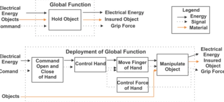
Through project requirements and the problem to be solved, the problem in question is to Hold Objects. From the functional structure represented in the flow chart of Fig. 1. The overall function of the product should relate the technical peripheral systems, which are classified into energy, material and signal, both inputs and outputs. Here we defined the inputs and outputs as: electrical energy, objects and command; electrical energy, insured object and grip force, respectively. Once the global function is defined, the deployment of the global function corresponds to a lower level, where the functions of the product are more specifically portrayed.
Fig. 1. Global function and deployment of global function for the anthropomorphic hand
Once the abstract functions of the product are defined, a solution principle is assigned for each of the functional structure sub-functions performed from the global func-tion deployment. The principles of solufunc-tion were generated through the brainstorming process. The main ones will be described, due to the complexity of project development:
1) To Generate Movement: The use of a dc micro-motor with reduction box is justified due to its low acqui-sition cost, whilst allowing a precise control through
command by Pulse Width Modulation (PWM). It has also got a reduction that increases its force, allowing the grip of objects weighing up to 1 kg. Also, because of its small dimensions, it allows the development of a robotic hand that approaches the dimensions of the human hand.
2) To Transmit Movement: A sub-actuated mechanism driven by pulley + cable allows it to keep the DOF of the mechanism, while the use of the pulley + cable assembly allows the finger to adapt to the shape of the object to be grasped, giving the hand dexterity, different from a mechanism with fixed links.
3) Type of Material for Manufacturing: As material for making the robotic hand, the use of 3D printing enables the production of the prototype in low cost, preserving the characteristics in project. In addition, it allows testing of the solution employed, as well as rebuilding of the part in case of design errors, to meet the needs specified by customers.
4) Manipulating Objects: A robotic hand with 5 fingers theoretically enables the manipulation of different ob-jects. It results in the appearance of the human hand, giving it the anthropomorphic characteristics desired by the customers of the product. It should be noted that the higher the number of fingers in the robotic hand, the more complex the design becomes.
5) Force Control: To enable the closing of the compli-ance loop, the Force Sensitive Resistor (FSR) [12] is employed in order to meet a simple and low-cost, yet functional solution. In case other sensors are used, it would be necessary to use signal converters, as well as more complex electronics.
6) Controller: The use of the Raspberry Pi 3 microcom-puter allows the use of customized solutions, allowing Ethernet integration, making possible the creation of a graphical interface for the user and the adoption of control strategies such as PID or Fuzzy. In the current version, it has a good data processing rate and aid resources to the development of integrated solutions. 7) Opening and Closing of the Hand: As for the hand
opening and closing control system, due to the use of Raspberry Pi 3 integration becomes easier, allowing the creation of a low-cost and open-source graphical interface. A proprietary solution would raise project costs exponentially.
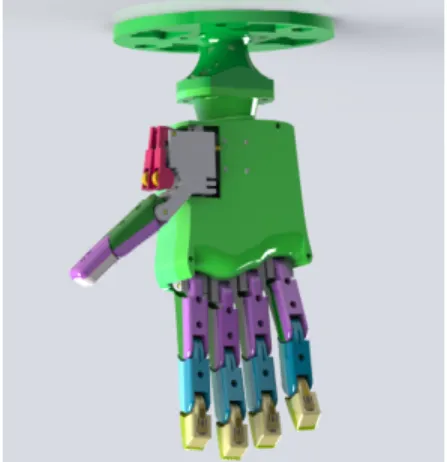
From the principles of solutions adopted, the preliminary view of the developed robotic hand can be visualized in Fig. 2.
C. Detailed Design
Through the generated design of the anthropomorphic robotic hand, this phase aims to, through the V model, specify the robotic hand on mechanical, electronic and computational levels. [13]. In the mechanical domain, the anthropomorphic robotic hand’s structure systems, kinematic calculations and mechanisms of transmission of movement
Fig. 2. Preliminary vision of robotic hand
are described. The process starts with the following mechanic project domain:
1) Mechanical Design: In the mechanical design, the kinematics calculations of the robotic hand are performed, afterwards the structure is described, which was done using CAD modeling. As the human hand is formed by the joints, the robotic hand is also described with said joints as: Metacarpophalangeal (MCP), Proximal Interphalangeal (PIP), Distal Interphalangeal (DIP) and Radio-Carpal (RC), for more information about the human hand, refer to the work of [14].
2) Direct kinematics for the pinky, ring, middle and index finger: For the anthropomorphic robotic hand developed in this paper, we use the Denavit-Hartenberg (DH) technique, to find where the fingers of robotic hand are positioned, considering the angles of rotational joints, described in [15]. The local references for the pinky, ring, middle and index fingers can be visualized according to Fig. 3. From the figure it can be seen that the reference systems possess mutually parallel axes. The direct kinematics is defined according to the parameters of Tab. II. Where licorresponds to the length of the joint.
Fig. 3. Representation of the local reference points of the pinky, ring, middle and index fingers
After developing the equations using the DH technique, the result is shown in Eq. 1, where the fourth column of the matrix represents the final position of the fingers of the robotic hand.
TABLE II
DHPARAMETERS FOR THE MINIMUM,RING,MIDDLE AND INDEX FINGERS Joints θ α l d MCP θ1 0 l1 0 PIP θ2 0 l2 0 DIP θ3 0 l3 0 T03= c123 −s123 0 l1c1+ l2c12+ l3c123 s123 c123 0 l1s1+ l2s12+ l3s123 0 0 1 0 0 0 0 1 (1)
3) Direct kinematics for the thumb: Direct kinematics for the thumb was defined analogously to the procedure previously employed. The local references to the thumb according to the DH notation is demonstrated in Tab. III and the explicit parameters in Eq. 2.
Fig. 4. Representation of the local reference points for the thumb
TABLE III
DHPARAMETERS FOR THE THUMB
Joints θ α l d RC θ1 90 l1 d1 MCP θ2 0 l2 0 DIP θ3 0 l3 0 T03= c23.c1 −s23.c1 s1 c1(l1+ l3c23+ l2c2) c23.s1 −s23.s1 −c1 s1.(l1+ l3.c23+ l2c2) s23 c23 0 d1+ l3.s23+ l2.s2 0 0 0 1 (2)
D. Description of mechanical domain systems
The description of the anthropomorphic robotic hand is performed from the mechanical domain through CAD modeling. Only the part of the transmission of the fingers will be shown, for it is the most important. But the entire project can be found on the website described in results. The main fingers have a unique structure between all fingers that are replicated to the others, except for the thumb. The transmission of the finger is based on the project The Open Hand [16]. The leading fingers are described in Fig. 5.
Fig. 5. Description of components common to the pinky, ring, middle and index fingers
The fingers (pinky, ring, middle and index), shown in Fig. 5, have got DC motors (12) which, through the spiral pulley (13), transmit the movements to a nylon thread which is connected to the MCP phalanges, PIP and DIP. The pulley has a structure with nylon wire fastening to enable it to wrap around itself to allow flexing or stretching of the finger. The base of the DC motors (10) enables said motors to be secured, while the extenders (16) together with the V-grooved windings (18) enable the nylon thread to be tensioned through the spring (19). The finger structure, the phalanges MCP (4 and 1), PIP (7 and 6) and DIP (9 and 8) are connected via the shaft (11) to the base of the motor to enable the transmission of movements. The phalanges have bearings (5) to allow smooth movement, while the phalanges are fixed by the bolts and nut (2) (3). FSR sensors are positioned at the fingertips (20) to enable active compliance control. The assembly of the fingers can be seen in Fig. 7.
The thumb, represented in Fig. 6, has a different assembly, since, in addition to performing the extension and flexion movements, it does the abduction and adduction movements. To enable extension and flexion movements, there are DC motors fixed to the back of the palm. By means of the nlyon spring (13), spring (15), bearings (9) and shaft (10) extenders, the MCP (5 and 6) and DIP (7 and 8) phalanges can be moved. The movement of the RC phalanx, which is constituted by the support base (1) of the servomotor (2), allows the abduction and adduction movements. The base of the RC phalanx is fixed to the back of the palm, which can be seen in Fig. 7. The servomotor shaft (3) makes it possible to transmit the movements of said servomotor to the thumb drive assembly, while the bearing assembly (4) enables smooth movement of the phalanges. The phalanges are fixed by the screws (11) (12). The FSR sensor (16) enables thumb compliance control.
The assembly of the complete hand including all parts described above and represented by colors can be visualized in Fig. 7 for better understanding. The complete assembly of the anthropomorphic robotic hand has 47 pieces. The entire project can be found on the website URL https://www. arturvitorio.weebly.com.
Fig. 6. Description of components for the thumb
Fig. 7. Rendered CAD drawing of the complete anthropomorphic robotic hand
E. Compliance Control1
Compliance control was developed for all 5 fingers in a single Raspberry Pi 3+. Fuzzy logic control is used in alternatives to classical PID control, due to the complexity of the system being addressed. The force control is given as a function of the pressure read by the FSR sensor and the user defined pressure setpoint. The rules were defined based on tests and bibliographical references in order to obtain the best force control with a low computational cost. In Tab. IV the fuzzy rules defined for the force control are shown.
TABLE IV
COMMAND MATRIX FOR FORCE CONTROL VARIABLE FROM THE FORCE MEASUREMENT VARIABLE AND FORCE SETPOINT
Force Force Setpoint
Low Normal High Low Not Change High High Normal Low Not Change High
High Low Low Not Change Overall there are 6 rules to accommodate all combinations of intersections of force and setpoint of force to be able to control, in linguistic terms, the force applied on the object. Since the rule does not change, it corresponds to the system error equal to 0, being the force of the actuator equal to
1A control system to safely replicate the movements of the hands during
the force required by the system, thus obtaining compliance control.
III. RESULTS
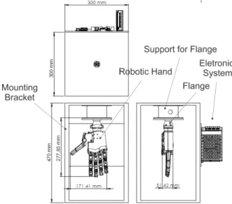
In order to accommodate the developed robotic hand and the electro-electronics of the project, a wooden support structure was developed, as presented in Fig. 8. In addition to providing the support for the robotic hand, it ”simulates” the coupling link of a robotic manipulator.
(a) The clamp mounted on the support simulating the coupling of a manipulator
(b) The electronics set to en-able control of the robotic hand
Fig. 8. Structure in Medium-Density Fiberboard (MDF) with the mounted anthropomorphic robotic hand
The simulation to verify the calculated values and geomet-ric parameters was done on SolidWorks software, through Toolbox SolidWorks Motion. As an example, we have through Tab. V a comparison between the values calculated through the proposed kinetics and measured through Solid-Works.
TABLE V
COMPARISON OF CALCULATED AND MEASURED KINEMATICS
Values MCP, DIP, PIP X Y Z Matlab 25, 30, 60 46.31 mm 71.58 mm 0 mm SolidWorks 25, 30, 60 48.15 mm 71.07 mm 0 mm Error 25, 30, 60 1.84 mm 0.51 mm 0 mm
Through Tab. V it can be observed that between the value calculated in the simulation and the position of the robotic hand for the considered finger there is an error of 1.84 mm in the X axis and 0.51 mm in the Y axis in the position of the considered phalanges. This error is due to the initial position of the mechanism, since said initial position is not exact. There is a need to lock the mechanism in a reference position to take the measurement.
IV. COMPLIANCECONTROLSYSTEM
With the tactile perception control developed, it was possible to execute the control algorithm in a Raspberry for the five fingers of the developed robotic hand, due to the implementation of the fuzzy control [17] that has low computational cost, at the same time. The response time for the five fingers was about 300 ms, and the CPU consumption reached 95%. In Fig. 9 it is possible to observe the behavior of the system for the setpoint of 2 N.
Fig. 9. Control system response for a 2N setpoint
The objects considered for manipulation are an insulation tape, a universal plier, a pen, a multimeter, a protoboard, a 15mm combination wrench, a glue stick, an elliptical shaped object printed in 3D and and allen key. These objects were considered in order to test the dexterity of the robotic hand. In Fig. 10 the objects considered for manipulation can be observed. The manipulation of the pen, as it has a minimum thickness, besides having a cylindrical shape, due to the manipulation of the robotic hand and the work area between the thumb and index finger, turns performing the grip complicated, the same happening to the allen key. However, if the manipulation of the pen and the allen key is performed with the pinky, ring, middle and index fingers said manipulation becomes satisfactory. It should be noted that for future work, it is necessary to perform a form of validation using statistical methods in order to validate the developed grips. The URL https://www.youtube. com/watch?v=2Ze1eRsB3bUshows the manipulation of some considered objects.
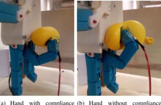
In Fig. 11 the difference in balloon grip for the adopted compliance adjustment is demonstrated. For Fig. 11(a) we set the setpoint to 2N of force, while for the Fig. 11(b) we set the setpoint to 7.82N, where we can observe the deformation of the grip on the balloon. In the figures the behavior of the force adjustment for the considered grip is also demonstrated. In the URL https://youtu.be/ Nq8-_jBQJoI a setpoint ramp related to the compliance control is demonstrated.
(a) Hand with compliance control
(b) Hand without compliance control
Fig. 11. Compliance adjustment
V. CONCLUSION
In general, the development of the anthropomorphic robotic hand was effective, where the hand has the anatomi-cal shape of the human hand, having 5 fingers, one of them being the thumb, meeting some of the target specifications. The use of the anthropomorphic robotic hand allows the manipulation of objects with different weights and sizes, allowing the grip with stability. While the robotic gripper with two fingers handles only about 40% of everyday tasks, the robotic hand enables manipulation of almost all objects. Based on the target specifications required in Tab. I for the developed robotic hand, items 1.3, 1.5, 1.7, 3.1 and 3.2 were not satisfactorily achieved or not estimated. For item 1.3, considering the motors are small to fit internally in the palm of the hand, they do not have a maximum capacity of 2kg/cm. According to the datasheet of the motor used, it has 1kg/cm. For item 1.5, generation of the graphical interface had to be performed through the Node-RED software to enable the decentralization of the client-control system to maintain system efficiency. As for item 1.7, according to the author’s limitations, it was not possible to estimate the accuracy of the control system developed. For items 3.1 and 3.2, the movements of the fingers occurred in a general way, since there is a need to make improvements in the gripper to allow classification of the grip. However, these items, according to the hierarchy of customer requirements, were not of paramount importance, for example, compliance control and the appearance of the robotic hand, which was reached.
According to the developed kinematic analyses, the mech-anism presented errors between 0.28mm and 1.83mm due
to initial positioning errors. The measurement was done through SolidWorks software and compared with the values calculated through the DH algorithm. However, the results are satisfactory, where the developed kinematic model cor-responds to the real kinematic model of the robotic hand.
As for the compliance control system, it is necessary to adjust the fuzzy logic for the setpoints of force of less than 0.5N and greater than 8N. Due to the use of the minimum set of fuzzy sets for the considered operation ranges, the system becomes inefficient. It should be noted that for the compliance control system developed the response time was about 300ms for the 5 fingers, according to tests performed in the compliance system. The entire project can be found on URL http://www.arturvitorio.weebly.com.
ACKNOWLEDGMENT
The authors would like to thank the financial support of the Brazilian government agencies MEC/CAPES/CNPq/FAPDF.
VI. REFERENCES
[1] Z. Kappassov, J. Corrales, and V. Perdereau, “Tactile sensing in dexterous robot hands — review,” Robotics and Autonomous Systems, vol. 74, pp. 195 – 220, 2015. [Online]. Available: http://www.sciencedirect.com/science/article/pii/S0921889015001621 [2] Y. Fernando, A. Mathath, and M. A. Murshid, “Improving
productiv-ity: A review of robotic applications in food industry,” 2016. [3] J. L. Pons, R. Ceres, E. Rocon, D. Reynaerts, B. Saro, S. Levin,
and W. V. Moorleghem, “Objectives and technological approach to the development of the multifunctional manus upper limp prosthesis,” 2016.
[4] A. Bicchi, “Hands for dexterous manipulation and robust grasping: a difficult road toward simplicity,” IEEE Transactions on Robotics and Automation, vol. 16, no. 6, pp. 652–662, Dec 2000.
[5] R. S. Johansson and J. R. Flanagan, “Coding and use of tactile signals from the fingertips in object manipulation tasks,” Nature Reviews Neuroscience, 2009.
[6] M. Prats, ´A. P. Pobil, and P. J. Sanz, Robot Physical Interaction through the combination of Vision, Tactile and Force Feedback: Applications to Assistive Robotics, ser. Springer Tracts in Advanced Robotics. Springer Berlin Heidelberg, 2012. [Online]. Available: https://books.google.com.br/books?id=3r25BQAAQBAJ
[7] X. Yulin, J. Caijun, and Y. Jie, “Compliance control for grasping with a bionic robot hand,” 2016.
[8] M. Tavakoli and A. T. de Almeida, “Adaptive under-actuated anthro-pomorphic hand: Isr-softhand,” 2014.
[9] H. Liu, K. Wu, P. Meusel, N. Seitz, G. Hirzinger, M. H. Jin, Y. W. Liu, S. W. Fan, T. Lan, and Z. P. Chen, “Multisensory five-finger dexterous hand: The dlr/hit hand ii,” in 2008 IEEE/RSJ International Conference on Intelligent Robots and Systems, Sept 2008, pp. 3692–3697. [10] K. Ulrich and S. Eppinger, Product Design and Development.
McGraw-Hill Education; 5 edition, 2012.
[11] L. C. Cheng, QFD – planejamento da qualidade, 1195.
[12] “Force sensing resistor integration guide and evaluation,” https://www. interlinkelectronics.com/fsr-402, accessed: 2018-07-19.
[13] G. Pahl, W. Beitz, H. Schulz, and U. Jarecki, Pahl/Beitz Konstruktion-slehre: Grundlagen erfolgreicher Produktentwicklung. Methoden und Anwendung. Springer Berlin Heidelberg, 2013. [Online]. Available: https://books.google.com.br/books?id=qJkiBgAAQBAJ
[14] G. Cerruti, D. Chablat, D. Gouaillier, and S. Sakka, “Design method for an anthropomorphic hand able to gesture and grasp,” CoRR, vol. abs/1504.01151, 2015.
[15] S. B. Niku, Introduc¸˜ao a Rob`otica - An`alise, Controle e Aplicac¸˜oes. LTC, 2013.
[16] “The open hand project,” http://www.openhandproject.org/, accessed: 2017-07-19.
[17] C. C. Lee, “Fuzzy logic in control systems: fuzzy logic controller. i,” IEEE Transactions on Systems, Man, and Cybernetics, vol. 20, no. 2, pp. 404–418, Mar 1990.