Repositório ISCTE-IUL
Deposited in Repositório ISCTE-IUL:
2018-12-10Deposited version:
Post-printPeer-review status of attached file:
Peer-reviewedCitation for published item:
Matos, S. A., Lima, E. B., Costa, J. R., Fernandes, C. A. & Fonseca, N. J. G. (2018). Experimental evaluation of a high gain dual-band beam steerable transmit-array. In 12th European Conference on Antennas and Propagation, EuCAP 2018. London: Institution of Engineering and Technology.
Further information on publisher's website:
--Publisher's copyright statement:
This is the peer reviewed version of the following article: Matos, S. A., Lima, E. B., Costa, J. R., Fernandes, C. A. & Fonseca, N. J. G. (2018). Experimental evaluation of a high gain dual-band beam steerable transmit-array. In 12th European Conference on Antennas and Propagation, EuCAP 2018. London: Institution of Engineering and Technology.. This article may be used for non-commercial purposes in accordance with the Publisher's Terms and Conditions for self-archiving.
Use policy
Creative Commons CC BY 4.0
The full-text may be used and/or reproduced, and given to third parties in any format or medium, without prior permission or charge, for personal research or study, educational, or not-for-profit purposes provided that:
• a full bibliographic reference is made to the original source • a link is made to the metadata record in the Repository • the full-text is not changed in any way
The full-text must not be sold in any format or medium without the formal permission of the copyright holders.
Serviços de Informação e Documentação, Instituto Universitário de Lisboa (ISCTE-IUL) Av. das Forças Armadas, Edifício II, 1649-026 Lisboa Portugal
Phone: +(351) 217 903 024 | e-mail: [email protected] https://repositorio.iscte-iul.pt
Experimental evaluation of a high gain dual-band
beam steerable transmit-array
Sérgio A. Matos
1,2, Eduardo B. Lima
1, Jorge R. Costa
1,2, Carlos A. Fernandes
1and Nelson J. G. Fonseca
31 Instituto de Telecomunicações, Instituto Superior Técnico, IT/IST, Lisbon, Portugal, [email protected]
2 Instituto Universitário de Lisboa, (ISCTE-IUL), Lisbon, Portugal
3 European Space Agency, Antenna and Sub-Millimeter Wave Section, Noordwijk, The Netherlands
Abstract— This paper presents the design and measurement of a novel transmit-array (TA) that is able to combine wide beam steering and high gain for two distinct frequency bands. The TA is designed for a mobile ground platform to operate at satellite communications in the Ka-bands: Rx (19.7-20.2 GHz) and Tx (29.5-30.0 GHz). A 28 dBi gain is obtained for 30 GHz and 24 dBi for 20 GHz. The zenith beam steering results from a
linear displacement of the aperture ( × ) in front
of a stationary feed. A scanning range of 50º was obtained with 2dB scan loss. Overall, the dual-band TA performs as well as if two independent single band apertures were designed.
Index Terms— dual band, transmit-array, beam Steering, high gain, Ka-band satellite communications.
I. INTRODUCTION
Beam steering antenna research is of paramount importance in the present context of telecommunications, as millimeter waves are becoming the trend for the next generation of satellite and mobile communications (5G). Cost-effective solutions to achieve high gain and accurate beam pointing, are required for mass production. These antennas must also conform to the available size in the mobile ground terminals. A special attention has been given to transmit-arrays (TA). They tend to have lower costs than phase-arrays [1] and be more compact than usual reflector based antenna solutions [2]. On the other hand, TA are an appealing alternative to the reflect-array counterpart [3] due to the feed blockage, inherent to these systems.
Designing a TA for satellite-on-the-move Ka band ground terminals is especially demanding. It is required to operate in two widely separated Rx/Tx frequencies (20 GHz/30 GHz) with orthogonal circular polarizations. Moreover, in these systems switching right-hand circular polarization (RHCP) and left-hand circular polarization (LHCP) is also an important requirement for polarization diversity and handover. For this reason, polarization insensitivity is an important feature of this type of TA. It is possible to circumvent some of these difficulties by having two independent apertures (one for each band) however it impacts on the antenna size and cost [5]. In the current state-of-the-art exits TA solutions with dual band operation [6]- [8], high gain [7]-[10] wide beam steering [9], [10] and circular polarization [6], [9]-[11]. The challenge is to have a single aperture that simultaneously satisfies all the aforementioned specifications.
The TA can be classified by the type of unit cells that provide the phase shift along the aperture. With phase rotation (PR) cells the TA is assembled by placing the same unit cell with different rotation angles according to the necessary local phase shift [11]. PR TA acts as a filter for a given circular polarization (LHCP or RHCP). Therefore, PR TA cannot be used in polarization switching antennas (an important feature in satellite communications, as mentioned previously). On the other hand, the phase delay (PD) approach allows polarization insensitivity [9], [10], but requires the design of a family of unit cells, each providing a specific phase response. This design procedure is extremely difficult for dual band cells when aiming to populate an aperture of arbitrary size with low phase discretization errors. In [12] we presented a general method to simplify this design procedure for any two frequencies.
A PD TA can also be designed to operate for linear polarization as in [8]. A dual band (12/18 GHz) aperture
(240 × 240 ) with high boresight gain (27.8 dBi / 31.4
dBi) was achieved but without polarization insensitivity and wide steering. An alternative design approach, designated as the interleave technique, can be adopted. In this case, the aperture is constituted by a combination of single band Rx and Tx elements carefully arranged to minimize their mutual coupling. Ideally it would provide independent phase control in each band, but the coupling leads to poor cell transmissivity (as in the PR TA in [6] ) or limited phase correction (as in the PD TA [7] that has a 1 bit of phase resolution). In [6] only moderate boresight gain (19/20 dBi at 20/30 GHz) was
obtained for a 72 × 72 aperture. In [7] high dual band
gain (29 dBi at 29 GHz and a 26 dBi at 19.5 GHz) for a 180 ×
180 aperture was obtained. Nevertheless, this TA
operates only with linear polarization and provides moderate mechanical scanning coverage [-20 º, 20º].
In this work, we demonstrate experimentally a dual band PD TA operating at the Rx (19.7-20.2 GHz) and Tx (29.5-30.0 GHz) Ka bands that complies with all the aforementioned requirements: wide beam steering ([-50º,50º] with 2 dB scan loss), high circular-polarization gains (28 dBi at 30 GHz and 26 dBi at 20 GHz), and polarization insensitivity. We should stress that this approach allows to have the beams of each frequency pointing in the same direction along all scanning angles. This work is based on our previous publication [12]
where preliminary experimental results were given for a smaller aperture and limited scanning performance.
To assess the antenna performance, we established a set of requirements (TABLE I) based on the previous experimental results obtained for a single Ka-band PD TA [10]. The same
focal distance ( = 100 mm) and aperture size (196 ×
147 ) are used. Therefore, the maximum gain at 30 GHz
of the dual band TA should be similar to the one obtained in [10] (27.5dBi). According to the effective area dependence with frequency, we expect a gain reduction of 3.5 dB for 20 GHz (20 log1.5 ≈ 3.5 dB). As in [10] we also aim to get the scanning range [0, 50º] within the 3dB scan loss.
TABLE I – Dual band TA specifications
Antenna dimensions
In-plane dimensions (mm2) 196 ×147
Focal Distance (mm) 100
Scanning
Zenith scanning range (º) [0,50º] Azimuth scanning range (º) [0,360º]
Scan loss (dB) <3
Ka dual band system Rx Band Tx Band
Frequencies (GHz) 19.7-20.2 29.5-30.0
Gain (dBi) 27.5 24
Circular Polarization RHCP/LHCP LHCP/RHCP
II. DUAL BAND TRANSMIT-ARRAY A. Working Principle
The antenna working principle is depicted in Fig. 1. When the lens is aligned with the feed, the outgoing beam is tilted by (offset Fresnel design [10]). The remaining zenith beam coverage is obtained by moving the lens along x. As this displacement increases other aberrations arise, producing beam distortions and limiting the TA performance. The 360º scan in azimuth is obtained by rotating the TA around the axis of the feed, which does not affect the lens performance. The TA is supposed to be fed by a dual-band circular polarization feed. However, as a proof of concept, two rectangular horns are used to illuminate the TA, instead: Flann Microwave Nº 20240-15 for 20 GHz and Flann Microwave Nº 22240-15 for 30 GHz. Therefore, for each horn, two orthogonal linear polarization are measured, corresponding to the orientations 0º and 90º represented in Fig. 1. Then, the TA circular polarization response is evaluated by combining the two polarization results.
Fig. 1 - Working Principle B. Design
The transmit-array (TA) is assembled by choosing, for each point of the lens, the unit cell within the cell population that falls closest to the phase given by [12]
Φ = sin (1)
where is the free space wavenumber, = 100 is the
focal distance, , is the in-plane transmit-array coordinate
system (see Fig. 1) and is the aforementioned outgoing beam direction when the feed is at the focal point of the lens. As a beam gets tilted in relation to the zenith of the lens, its gain decreases due to the reduction in the antenna effective area resulting from the projection of the aperture of the lens in the wave front plane of the beam. To mitigate somewhat this
effect, the TA is designed with = 40° instead of 32º as in
[12], and therefore the higher value of favors the must tilted beams. Hence, it is expected a decrease of scan loss and an increase of SLL for the less tilted beams relative to the results obtained in [12].
The PD unit cell geometry is depicted in the inset of Fig. 2. These cells have a total height of 9.7 mm and are composed by seven layers of square metallized elements (3.5 ×
3.5 , corresponding to 0.35 × 0.35 at 30 GHz
and 0.23 × 0.23 at 20GHz). The metallic elements are
printed on six substrate layers of 60 mills (1.575 mm) Rogers
Duroid 5880 ( = 2.2, tan = 0.0009). The phase
variations are obtained by changing in each layer the number and thicknesses of the strip loops and the patch sizes. The optimization process resulted in a family of 30 unit cells with good transmission in both Rx and Tx Ka-bands (see Fig. 2). Further detail about the unit cells can be found in [12].
Fig. 2 - Transmission magnitude responses of the 30 dual-band unit cells [12].
III. TA PROTOTYPE PEFORMANCE
The printing of the layers’ pattern was made with the photolithography lens fabrication equipment that is available at the laboratory facilities which reaches a precision down to 50 micro, see Fig. 3 a). The bounding structure is composed of two solid slabs of iron that are used to sandwich the lens layers and bonding film. Six guiding pins are used to enforce the alignment between layers. The substrate layers are bonded using Rogers 3001 bonding film [13], requiring a high temperature cycle (240º C) under at least 200 psi pressure. The complete assembly was placed in the oven at ambient temperature and then heated up to 240ºC for 5 hours to ensure a uniform temperature distribution across the whole lens volume. After 10 hours of natural cooling down to ambient temperature, the lens was cut to its final dimensions. The lens was then assembled in the 3D printed support structure shown in Fig. 3 b). The measurements where
preformed for six feed positions along the x-axis: =
30, 15, 0, 30, 44, 81 mm.
Fig. 3 – (a) Prototype fabrication process showing the substrate laid on the iron slab and the alignment guides. (b) Assembled antenna composed of the
lens, horn and support structure.
A. Comparison between simulation and measurements
Fig. 4 shows a reasonable agreement between the radiation patterns of measurements and the CST simulations [14] in the scanning region [0, 50º] for the linear y-polarization. To reduce the memory requirements and allow for the full wave simulation of the antenna, an approximated equivalent Gaussian beam illumination was considered instead of the rectangular horn. Some differences between
measurement and simulations are then expected. Moreover, the anechoic chamber positioner supporting structure blocks the measurement of the antenna back lobes. This region is highlighted in Fig. 4 and clearly shows the deviations between measurements and simulations.
Fig. 4 - Comparison between measured and simulated y-polarization radiation patterns, normalized to the maximum of the central beam ( ). B. Antenna circular polarization performance
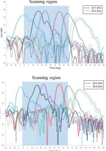
The performance of the lens in circular polarization is presented Fig. 5 for all measured beams and lens positions. The lens radiation pattern performance agrees with the expected values within the desired scanning interval. The scan loss is always below 1.8 dB and the beams are pointing at a common direction for the Rx and Tx bands. The obtained highest gain value is 28 dBi at the Tx band and 24 dBi at the Rx band. The 4dB difference between the gain at 20 GHz and at 30 GHz is almost completely justified by the effective area reduction with frequency (20 log1.5 ≈ 3.5 dB). In each band, there is not much degradation of the radiation pattern shape. However, comparing with simulations there is a minor beam depointing within the band, as well as a slight gain change (below 1 dB) for the most tilted beams. For the feed displacement of a=81 mm (corresponding to the 0º beam) there is significant spillover leading to an increase of SLL, see Fig. 5. Moreover, the choice of the central beam tilt of 40º Unit cell [12] a) b) -30 -25 -20 -15 -10 -5 0 -20 0 20 40 60 80 100 120 140 160 180 N orm al iz ed E le ct ri c f ie ld (r =1 .6 15 m ) (dB ) Theta (deg) 20 GHz y-pol a=-15 mm (measured) a=-15 mm (simulated) a=0 mm (measured) a=0 mm (simulated) a=44 mm (measured) a=44 mm (simulated) a=-30 mm (measured) a=-30 mm (simulated) a=30 mm (measured) a=30 mm (simulated) a=81 mm (measured) a=81 mm (simulated) Support blockage Scanning region Scanning region 20 GHz (y-pol) N or m al iz ed f iel d (d B ) -30 -25 -20 -15 -10 -5 0 -20 0 20 40 60 80 100 120 140 160 180 N or m aliz ed E le ctr ic f ie ld (r = 1.615 m ) (d B) Theta (deg) 30 GHz y-pol a=-15 mm (measured) a=-15 mm (simulated) a=0 mm (measured) a=0 mm (simulated) a=44 mm (measured) a=44 mm (simulated) a=-30 mm (measured) a=-30 mm (simulated) a=30 mm (measured) a=30 mm (simulated) a=81 mm (measured) a=81 mm (simulated) Support blockage Scanning region Scanning region 30 GHz (y-pol) N or m al iz ed f iel d (d B )
in order to mitigate the aforementioned antenna effective area reduction with beam tilt, has the consequence of increasing the SLL of the less tilted beams. Keep in mind that higher displacements translate in higher beam aberrations. If a lower value of was chosen (as in [10]) we would have, on the one hand, a better SLL for the less tilted beams, on the other hand, a higher gain degradation for the most tilted beams, thus affecting the scan loss. In fact, for the single band TA [10]
with = 32°, we obtained a higher scan loss (-2.8 dB) and
lower SLL in the less tilted beams. The TA cross-polarization level is always below -15 dB, hence we did not present the corresponding curves.
Fig. 5 - Right-hand circular polarization radiation patterns compared in the edges of the Rx and Tx bands.
IV. CONCLUSIONS
A prototype of a wide-angle beam scanning dual band planar lens that provides 28 dBi and 24 dBi gains at 30 GHz and 20 GHz, respectively, was experimentally demonstrated. We show that using an in-plane translation of the planar lens it is possible to achieve the aimed [0º, 50º] beam scanning with low scan loss (<1.8 dB in both Rx and Tx bands) with an F/D of 0.67. The develop TA can be a viable alternative technology for cost-effective ground terminals (trains, airplanes) of Ka-band satellite communication systems.
ACKNOWLEDGMENT
This work was supported in part by the European Space Agency under contract no. 4000109111/13/NL/AD and by the Fundação para a Ciência e Tecnologia under Projects PEst-OE/EEI/LA/0008/2013 and UID/EEA/50008/2013.
REFERENCES
[1] M. Tripodi, F. DiMarca, T. Cadili, C. Mollura, F. DiMaggio, and M. Russo, “Ka Band Active Phased Array Antenna System for Satellite Communication on the Move Terminal,” Proc. 5th European Conf. Antennas and Propag. (EuCAP), pp. 2628 - 2630, Rome, Italy, April 2011.
[2] H. Bayer, A. Krauss, R. Stephan, and M. A. Hein, “A Dual-Band Multimode Monopulse Tracking Antenna for Land-Mobile Satellite Communications in Ka-Band,” Proc. 6th European Conf. Antennas and Propag. (EuCAP), pp. 2357 - 2361, Prague, Czech Republic, March 2012.
[3] R. Deng, Y. Mao, S. Xu, and F. Yang, “A single-layer dual-band circularly polarized reflectarray with high aperture efficiency,” IEEE Trans. Antennas Propag., vol. 63, no. 7, pp. 3317-3320, May 2015. [4] L. D. Palma, A. Clemente, L. Dussopt, R. Suleau, P. Potier, and P.
Pouliguen, “1-Bit Reconfigurable Unit Cell for Ka-Band Transmitarrays,” IEEE Antennas and Wireless Propagation Letters, vol. 15, pp. 560-563, July 2015.
[5] A. Krauss, H. Bayer, R. Stephan, M. A. Hein, “A low-profile user terminal antenna for mobile bi-directional ka-band satellite communications,” Proc. 6th European Conf. Antennas and Propag. (EuCAP), pp. 2734 -2738, Prague, Czech Republic, March 2012. [6] H. Hasani, J. S. Silva, J. R. Mosig, and M. García-Vigueras,
‘‘Dual-band 20/30 GHz circularly polarized transmitarray for SOTM applications,’’ in Proc. 10th Eur. Conf. Antennas Propag. (EuCAP), Davos, Switzerland, Apr. 2016, pp. 1---3.
[7] K. Pham, R. Sauleau, , E. Fourn, F. Diaby, A. Clemente, L. Dussopt, “Dual-Band Transmitarrays with Dual-Linear Polarization at Ka-band,” IEEE Trans. Antennas Propagat., in press,.
[8] R. Y. Wu, Y. B. Li, W. Wu, C. B. Shi, T. J. Cui, “High-Gain Dual-Band Transmitarray,” IEEE Trans. Antennas Propagat, vol. 65, no. 7, pp. 3481-3488, Jul. 2017.
[9] N. Gagnon and A. Petosa, “Using Rotatable Planar Phase Shifting Surfaces to Steer a High-Gain Beam,” Antennas and Propagation, IEEE Transactions on, vol. 61, no. 6, pp. 3086-3092, June 2013. [10] E. B. Lima, S. A. Matos, J. R. Costa, C. A. Fernandes and N. Fonsenca,
“Circular Polarization Wide-angle Beam Steering at Ka-band by In-plane Translation of a Plate Lens Antenna,” IEEE Trans. Antennas and Propag., Vol. 63, No. 12, pp. 5443-5455, Dec. 2015.
[11] L. D. Plama, A. Clemente, L. Dussopt, R. Sauleau, P. Potier, and Ph. Pouliguen, “Circularly polarized transmit-array with sequential rotation in Ka-band,” IEEE Trans. Antennas Propag., vol. 63, no. 11, pp. 5118-5124, 2015.
[12] S. A. Matos, E. B. Lima, J. S. Silva, J. R. Costa, C. A. Fernandes, N. J. G. Fonseca, and J. R. Mosig, “High gain dual-band beam-steering transmit array for satcom terminals at Ka-Band,” IEEE Trans. Antennas Propagat, vol. 65, no. 7, pp. 3528-3539, Jul. 2017.
[13] https://www.rogerscorp.com/documents/637/acs/3001-Bonding-Film-Properties-and-Laminating-Techniques.pdf [Online], October 2017. [14] CST Microwave Studio. [2017, Oct.]. Computer Simulation
Technology [Online]. Available: http://www.cst.com.
-10 -5 0 5 10 15 20 25 30 -20 -15 -10 -5 0 5 10 15 20 25 30 35 40 45 50 55 60 65 70 75 80 85 90 Ga in (d B i) Theta (deg)
Design Scanning region
19.7 GHz 20.2 GHz 3dB scanning region
Scanning region
Design Scanning region
29.5 GHz 30.0 GHz -30 -20 -10 0 10 20 30 -20 -15 -10 -5 0 5 10 15 20 25 30 35 40 45 50 55 60 65 70 75 80 85 90 Ga in (d Bi ) Theta (deg) Scanning region

![Fig. 2 - Transmission magnitude responses of the 30 dual-band unit cells [12].](https://thumb-eu.123doks.com/thumbv2/123dok_br/18654419.912694/4.892.59.410.85.288/fig-transmission-magnitude-responses-dual-band-unit-cells.webp)