College of Engineeering. Qassim University. P.O.B 6677 Buraydah 51452. KSA, [email protected]
2Laboratoire d’electronique. Faculte des Sceinces de Tunis.
EL MANAR University. Tunisia [email protected]
Abstract: This paper is devoted to the design of a novel Electromagnetic Band Gap (EBG) circularly polarized slot-patch antenna in multilayered configuration. The operating frequency band can be controlled via the disk radius and adjusting the slit lengths. An arrangement combining the circular slot-patch antenna design and feeding sources included are considered is necessary. Due to the exisiting of two feeding points, Position of both feeding points will permit Right-hand and Left-hand circular polarization operations. Thickness of substrate is chosen to reduce the spurious surface wave and width. The same technique will be used for the EBG cirlcularly polarized circular slot-patch antenna network and carry two benefits (such as improvement of bandwidth, beamforming, creating zero radiation beams) and filtering characteristics of the resonator (spatial filtering, increased directivity, misalignment) due to the resonant structure itself. The analysis provided will confirm successfully the various proposed structures and interest occupied by these types of antenna. Two approaches, one introduced by one layered Circularly-Polarized Patch-Slot antenna design with some changes in material configuration and the other produced by multilayered structures with different dielectric constants in the EBG resonator, are simultaneously used as key controllers of directivity enhancement.
Index Terms— Electromagnetic waves & Propagation; Electromagnetic Band Gap (EBG) resonator; Circularly Polarized Slot-Patch Antenna; Antennas Array; Electric & Periodic lateral walls; Dimensional characterization
I.
INTRODUCTIONIn many telecommunication applications, particularly for the radio-relay, systems must radiate in
circular polarization. These systems must present the same characteristics as an antenna with linear polarization (high gain, simplicity of realization, etc.). To fulfill these conditions, patch array
antennas [1], reflector antennas, or horns are commonly used. A new concept of directive electromagnetic band gap (EBG) antenna will be analyzed [2], [3]. Hence, the electromagnetic
dielectric materials and metallic conductors [4], that prevent/assist the propagation of electromagnetic waves in a specified band of frequency for all incident angles and all polarization
states. They offer pass-band and stop-band (band-gap) to electromagnetic waves in the same way as the semiconductor do in electronics. Another important characteristic of these materials is the
ability to open localized electromagnetic modes inside the forbidden frequency band-gap by introducing defects in to the periodic structures [4]. EBG structures have been used in several
applications, such as Directive antennas [5], harmonic control [6].
Using these kind of EBG structures, more attractive features are offered such as low profile, light weight, easy fabrication, integrability with microwave and millimeter-wave integrated circuits, and
conformability to curved surfaces [1]. Such a design can avoid the use of multiple antennas, like for instance, by integrating receiving and transmitting functions in to the same communication system.
The dual frequency operation is achieved when the slots perturb the fundamental resonant frequency of the patch exciting a new resonance mode. The resonance frequency of the new mode
can be either orthogonal polarization [4] or lower [4,5] or higher [6] than the original dominant mode with either the same [7] and is strongly dependent on the slot dimensions. The
electromagnetic band gap (EBG) structures are defined as artificial periodic (or sometimes non-periodic) objects that prevent/assist the propagation of electromagnetic waves in a specified band
of frequency for all incident angles and all polarization states.
With Four Inserted Slits in the multilayered Circular patch-slot EBG antenna as the fundamental
structure (Figure 1) and with dual-sources [9]. The patch-size reduction is achieved by cutting four equally spaced slits at the boundary of the circular patch. The role of multilayered configuration is
proved by presenting their impact on the radiation, gain & bandwidth. This kind of multilayered Circularly Polarized Slot-Patch EBG antenna is found useful for wireless communication systems as it presents the desired performances. Improvement of bandwidth and gain and multiple operating
frequencies needed for different devices can be achieved by modification of physical parameters such as radius, thickness and type of dielectric substrate. Comparison of performance of proposed
design with conventional patch-slot circular antenna having identical patch radius and with same slits has also been reported and compared to analytic methods for better understanding.
The principle of the EBG resonator antennas is described in the first part of this work. The principle of circular polarization is shown. Simulation and analytic results at 9.1 GHz are
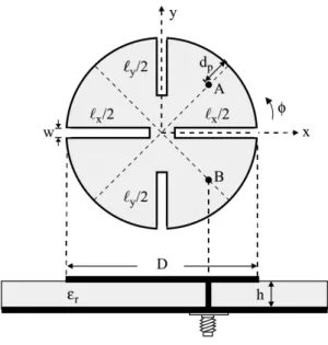
Fig. 1. Geometry of a circularly-polarized circular microstrip antenna with four inserted slits.
II.
EBG PATCH-SLOT CIRCULAR ANTENNA DESIGNThe substrate material plays a significant role in the design and simulation of microstrip patch antenna. The material selection depends upon permittivity, conductivity, thermal expansion and
cost. In this work, the substrate material with dielectric constant of 4.4 and dielectric loss tangent of 0.009 [10-13].
The electromagnetic band gap (EBG) structures defined previously as artificial periodic (or
sometimes non-periodic) objects will prevent/assist the propagation of electromagnetic waves in a specified band of frequency for all incident angles and all polarization states. Another important
characteristic of these materials is the ability to open localized electromagnetic modes inside the forbidden frequency band-gap by introducing defects in to the periodic structures [10]. They have
been used in several applications, such as Directive antennas [11], harmonic control [12]. Here, a novel design of single & multilayered patch-slot circular microstrip EBG antenna having
displacement of the coaxial feeding source from the center of the circular patch is proposed and its simulated radiation performances in free space conditions have been presented. The impact of the
permittivity is presented.
A. Circularly Polarized Patch-Slot Antenna Design
Next figure shows the geometry of a compact circularly polarized circular microstrip antenna. The circular patch has a radius D, and four narrow slits equally spaced and inserted at the boundary of
substrate material with a relative dielectric constant of 4.4 with thickness of 1.6 mm. The diameter of the circular patch is 3.2cm. Length of the slots (lx, ly) are varying from (10,5) to (25,24,5), Width
of the slot= 0.05 cm, Radius of the feed element=0.025 cm. Two Coaxial feedings are used to ensure the circular polarization. Hence, When the ratio of the total slit length in the slot in
x-direction (Lx) to that in the y-x-direction (Ly) is properly chosen, the two near-degenerate modes can be excited, using a single feed along the diameter at φ=450 planes, to be of equal amplitudes and
900 phase difference, which results in a CP radiation. When Lx is greater than Ly, the feed position at point A is for right-hand CP operation, while point B is for left-hand CP operation. The two slits on the x axis have the same length Lx, and the two slits on the y axis have an equal length Ly. and
insure that Lx> Ly Then, by varying x (0 < x < y).
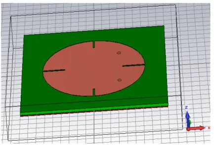
Fig. 2. Circularly Polarized slot- Patch Antenna
Table 1 shows Return Loss, VSWR and 2-D Gain for the designed circular patch-slot antenna with substrate thickness from 1mm to 2mm in the steps of 0. 2mm. A comparative analysis is made for
the obtained results.
Table 1. Circularly polarized Patch-Slot Antenna Output Parameters
Parameter Substrate Thickness
1.4mm 1.6mm 1.8mm
1 Return Loss
(dB)
-14 at 10.4 GHz -21.9 at 9.1045 GHz -19.553 at 7.53 GHz
2 VSWR 1.78 1.59 1.23
Fig. 3. Radiation Patterns of Circularly Polarized Patch-Slot Antenna
Previous figure, shows the analysis of S11 for dual-frequency operation specific value of thickness h=1.6; εr=4.4, ω=1 mm, d=32mm, lx=10, ly=5 mm. S11 gives the reflection coefficient at is
9.1045Ghz. It should be less than -10 dB for the acceptable operation which give the measure two bandwidths of 74 MHz. The simulated impedance bandwidths more than 75 MHz and reflection coefficient value suggest that there is good matching at the frequency point below the -10 dB
region. It covers the X frequency band for military requirement for land, airborne and naval radars applications. The radiation power shows the maximum peak value at resonant frequency
corresponding to the structure of substrate with thickness 1.6 mm.
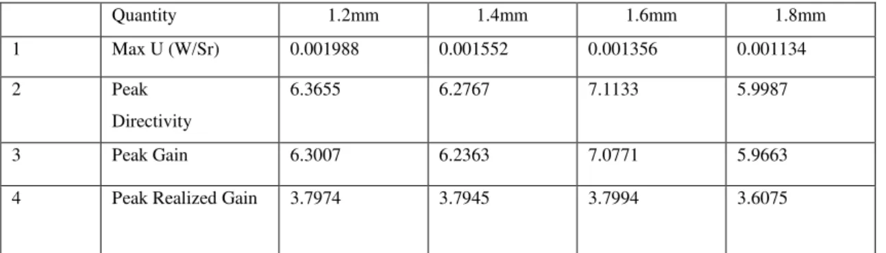
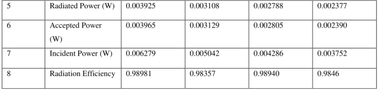
Table 2 shows the antenna additional parameters with respect to the change in the thickness of the
substrate. The far-zone electric field lies in the E-plane and far-zone magnetic field lies in the Hplane. The patterns in these planes are referred to as the E and H plane patterns respectively.
These parameters concern the radiation power, total efficiency and Return losses (dB)
Table 2. Additional Antenna Parameters of the Circular Slot-Pacth Antenna
Quantity 1.2mm 1.4mm 1.6mm 1.8mm
1 Max U (W/Sr) 0.001988 0.001552 0.001356 0.001134
2 Peak
Directivity
6.3655 6.2767 7.1133 5.9987
3 Peak Gain 6.3007 6.2363 7.0771 5.9663
5 Radiated Power (W) 0.003925 0.003108 0.002788 0.002377
6 Accepted Power
(W)
0.003965 0.003129 0.002805 0.002390
7 Incident Power (W) 0.006279 0.005042 0.004286 0.003752
8 Radiation Efficiency 0.98981 0.98357 0.98940 0.9846
In all next design and analysis, we fix the thickness of the substrate h=1.6mm
The summary of the comparison study is detailed in the next table shown below. Hence, we have
optimized the length of slots and their impact on the resonance frequencies and bandwidths.
Table 3. Impact of the geometric parameters of the slot (Length and width) on the Antenna Parameters of Circularly polarized Patch-Slot Antenna
Lx, Ly
(mm)
Dp/D (mm)
f (GHz)
10, 5 0.28 9.1045
14, 8 0.30 9.0435
14, 10 0.33 8.91425
14, 12 0.37 8.7825
From the simulated structure and based on modification of different geometric parameters, the
frequency ratio can be controlled.
B. Patch-Slot Circular Single Antenna Using EBG Structures with Magnetic Lateral Walls
The circular patch-slot geometry discussed above has been modified by the insertion of new EBG materials and see the influence of the number of layers on the performance of the antenna while
keeping the same dimensions as before concerning the patch and lateral conditions walls. The distance between the patch and the first dielectric layer is λ0 / 2 = 16.5 mm and the layer thickness
is λg / 4 =9.62mm.
Note that in this section, the dielectric permittivity of the different included layers is fixed εr = 4.4
and only the number of layers varies.
(a)
(b)
(d)
Fig. 4. Circularly Ploarized Patch-slot EBG antenna and its Reflection coefficient S11 (a) 1-layered, (b) 2-layered, (c)
3-layered, (a) 4-layered
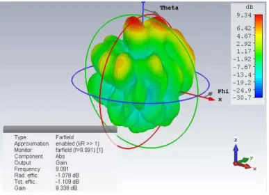
The reflection coefficient shows S11 (dB) = -54 dB, so layer of Plexiglas did not destabilize the
matching of the antenna. If we search the impact of these layers on the radiation pattern of antenna, the 3D radiation pattern of this antenna shows that the radiation has a greater directivity equal to 10.4dB which is normal since the parallel EBG materials increase directivity, gain; therefore, we
get a longer range of transmission.
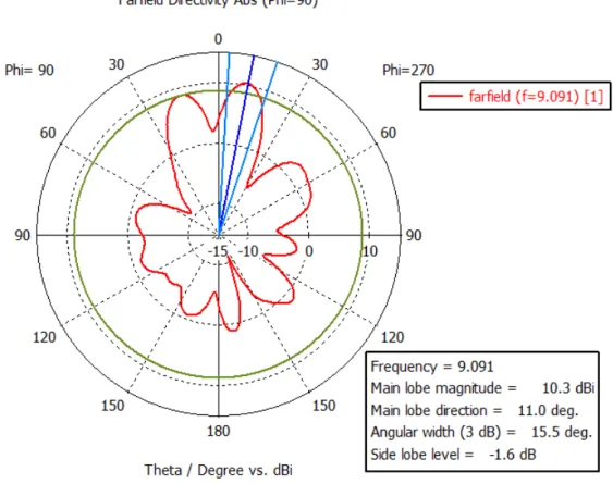
Fig. 6. Polar radiation pattern of an the circularly-polarized Slot-Patch EBG antenna within a Plexiglas layer plane E
The opening angle decreased significantly in fact, it passes from 80.4 deg to around 20 degrees with a preferred direction of propagation along the z axis which confirms our studies on the effects
of these materials defects. So we move from a unidirectional antenna to a directional antenna in the axis perpendicular to the patch. The side lobes pass from -16.5 dB to -1.2 dB what means a very
good control of the transmission bandwidth.
After we have fixed the geometric parameters of the desired EBG Slot-Patch antenna (thickness of the substrate, desired permittivity, width and length of the slots), we intended to analyze the impact
of number of Layers on the main output parameters of the double bandwidth EBG slot-patch Antenna.
Here, we must add to our patch new EBG materials and see the impact of the number of layers on the performance of the antenna while keeping the same dimensions as before the patch and
conditions power side (thickness of the substrate h=1.6mm, εr=3.6, Slot width=4mm and Length
(Lx=10, Ly=5 mm), Radius of patch R=32 mm). The distance between the patch and the first
dielectric layer is λ0 / 2 = 16.5 mm and the layer thickness is λg / 4 = 9.62mm.
The summary of the comparison study is detailed in the next table shown below.
As the number of layers’ increases, the gain increases against the opening angle decreases so the antenna is more directive. Note that the directivity and bandwidth increase with the number of EBG layers.
III.
CIRCULARLY POLARIZED MULTILAYERED SLOT-PATCH EBG ANTENNA IN PERIODIC CONFIGURATIONThe objective in this section is the design of an infinite Circular EBG slot-patch antenna array. Since the conventional technology presents some limitations such as those in coupling between
elements, stability, complexity, the New Multilayered EBG Slot-patch antenna array has the aim to rectify some of these limitations. It is designed to cover high directivity, covering navigation
systems, and be substitute for conventional technology antennas. It has been applied with the main challenge here complying with all the specifications given by Wide Area Augmentation System
(WAAS). High directivity, stable Axial Ratio and phase center were the most critical parameters. Several EBG technologies have been designed [14,15]. In our case, it is fundamental to analyze a prototype of single circular EBG Slot-patch antenna with periodic lateral walls. Hence, we can
obtain an optimization for the infinite array. At the same time antenna dimensions are significantly reduced by the use of high dielectric EBG constant substrates while maintaining high efficiency
values. Some precautions regarding the sources placement and coupling should be taken. It is then necessary to check parameter levels all along the antenna operating band: A high coupling level
can perturb the global functioning of the antenna array. In our case, this kind of circular multilayered EBG slot-patch antenna with periodic lateral walls is designed and the multilayered
technology is checked to give us an idea on the entire attitude of the periodic circular planar EBG slot-patch antenna network. Here, we Keep the same geometric parameters as the previous analysis.
Hence, we introduce new change concerning the lateral walls in order to could analyze a whole network composed by infinite patches. That periodic lateral walls condition is very important in
Number of layers = 1
Number of layers = 2
Number of layers = 3
Number of layers = 4
f (GHz) 9.104 9.104 9.104 8.984
S11 (dB) -34 -54 -32.2 -19.868
Gain (dB) 9.273 9.336 7.98 7.056
Directivity (dBi) 10.42 10.41 9.174 9.990
Linear value of Total efficiency
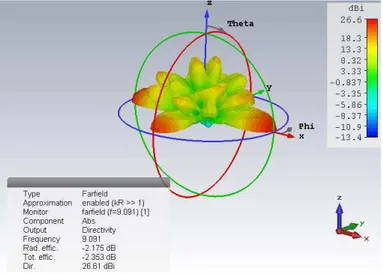
Fig. 7. 3D radiation pattern of a 2-Layered Circularly Polarized Slot-Patch EBG antenna with periodic walls
The change in number of layers of material shows the ability to increase gain and make more
directive antenna according to the preferred propagation direction. But, it does not directly affect the bandwidth.
Table 5. impact of number of dielectric layers on the EBG antenna network
By increasing the number of layers, we decrease stability (presence of ripples in S11). The change
in number of layers of material shows the ability to increase gain and make more directive antenna according to the preferred propagation direction. This does not directly affect the bandwidth.
Lateral periodic walls Number of layers = 1
Number of layers = 2
Number of layers = 3
Number of layers = 4
f (GHz) 9.0794 9.0914 9.104 9.075
S11 (dB) -18 -33.215 -18.06 -9.4
Gain (dB) 13 24.23 23.95 18.6
Directivity (dBi) 14.43 26.61 26.09 22.64
Linear value of Total efficiency
IV.
CONCLUSIONComparative analysis of Circularly-Polarized Slot-Patch and circularly Ploarized Solt-Patch EBG antenna was done by insertion of new EBG substrates in the aim to perform the electromagnetic characteristics (Gain, Bandwidth, radiation efficiency…) and changing the substrate thickness. Antenna parameters are ddeply changing in function of number of EBG substrates. From obtained results, the ideal number of EBG substrates is limited to two layers considering the different output parameters (Gain, bandwidth, directivity…). Either, the gain is increasing first and then decreased when thickness increases from 1.2mm to 1.8mm for the Circularly-Polarized slot-patch EBG
antenna. The same behavior is observed for the case of radiation efficiency, peak gain and peak directivity. Overall we observed that the stability in the performance characteristics for
Circularly-Polarized slot-patch EBG antenna is showing superior results compared to the circularly-Ploarized Slot-Patch antenna. Especially in case of infinite array and the introduction of the periodicity factor.
In this case, searching infinite array, while maintaining mutual interference between patches is worthy obtained with improvement of performance in comparaison with classic arrays
REFERENCES
[1] K.L. Chung and A.S. Mohan, a systematic design method to obtain broadband characteristics for singly-fed electromagnetically coupled patch antennas for circularly polarization, IEEE Trans Antennas Propag 51, 2003, 3239–
3248.
[2] Constantain.A. Balanis, Antenna Theory Analysis and Design. III Edn, Wiley-Interscience. A John Wiley&sons Inc.Pulication, 2005.
[3] K.-L. Wong and T.-W. Chiou, Broad-band single-patch circularly polarized microstrip antenna with dual capacitively coupled feeds, IEEE Trans Antennas Propag 49, 2001, 41–44.
[4] J. Y. Jan and K. L. Wong, “Single-feed dual-frequency circular microstrip antenna with an open-ring slot,” Microwave Opt. Technol. Lett. 22, 1999, 157–160, Aug. 5.
[5] Antennas for Base Stations in Wireless Communications (Book). Zhi Ning Chen & Kwai-Man Luk. Mcgraw Hill Professional, Jun 2, 2009
[6] K.F.Lee & W.Chen, “Advances in microstrip and printed Antennas”, John Wiley &sons, Inc.1997
[7] David M. Pozar, Daniel H. Schaubert "Microstrip Antennas: The Analysis and Design of Microstrip Antennas and Arrays" John Wiley & Sons, 1995
[8] Sathish Chandran"Adaptive Antenna Arrays: Trends and Applications" Springer, 2004.
[9] T. W. Chiou, H. C. Tung, and K. L. Wong, “A dual-polarization wideband circular patch antenna with hybrid feeds,” Microwave Opt. Technol. Lett., 26, July 5 2000, 37–39.
[10] R.Sauleau ,“Fabry Perot resonators “,Encyclopedia of RF and Microwave Engineering, Ed K.Chang, John Willey & Sons, Inc., Vol.2, May 2005, pp 1381-1401.
[16] Young Ju Lee, junhoyeo, Raj Mittra and Wee Sang Park “Application of Electromagnetic Bandgap
(EBG)Superstrates with Controllable Defects for a Class of Patch Antennas as Spatial Angular Filters” IEEE Trans Antennas. Propag VOL. 53, NO. 1, January 2005
[17] T. Weiland,”A discretization method for the solution of maxwell’s equations for six-component fields. Electronics and Communications”, AEÜ, 31(3) ,116–120, 1977.