FINITE ELEMENT MODEL FOR ACTIVE CONTROL OF ADAPTIVE LAMINATED STRUCTURES
José Simões Moita
Universidade do Algarve, Escola Superior de Tecnologia Campus da Penha, 8000 Faro, Portugal
Cristóvão M. Mota Soares Carlos A. Mota Soares
IDMEC/IST–Instituto Superior Técnico Av. Rovisco Pais, 1049-001 Lisboa, Portugal [email protected]
Abstract. A finite element formulation for active vibration control of thin plate laminated structures with integrated piezoelectric layers, acting as sensors and actuators is presented. The finite element model is a nonconforming single layer triangular plate/shell element with 18 degrees of freedom for the generalized displacements and one electrical potential degree of freedom for each piezoelectric element layer, and is based on the Kirchhoff classical laminated theory. To achieve a mechanism of active control of the structure dynamic response, a feedback control algorithm is used, coupling the sensor and active piezoelectric layers, and Newmark method is used to calculate the dynamic response of the laminated structures. The model is applied in the solution of several illustrative cases, and the results are presented and discussed.
Keywords: Sensor and Actuators, Laminated Structures, Finite Elements.
1. INTRODUCTION
In the recent years the study of smart structures has attracted significant researchers, due to their potential benefits in a wide range of applications, such as shape control, vibration suppression, noise attenuation and damage detection. The use of smart materials, such as piezoelectric materials, in the form of layers or patches embedded and/or surface bonded on laminated composite structures, can provide structures that combine the superior mechanical properties of composite materials and the capability to sense and adapt their static and dynamic response. The piezoelectric materials have the property to generate electrical charge under mechanical load or deformation, and the reverse, applying an electrical field to the material results in mechanical strains or stresses.
Shape control and dynamic control of structures are some of the current applications of the commonly referred intelligent structure described by Crawley and Luis (1989). A pioneering work is due to Allik and Hughes (1970), which analysed the interactions between
electricity and elasticity by developing a tetrahedral finite element. Recent surveys can be found in Senthil et al. (1999), Benjeddou (2000), and Franco Correia et al. (2000).
Several researchers have carried out the modelling of composite structures containing piezolaminated sensors and actuators using the finite element formulation. Samanta et al. (1996), developed an eigth-noded quadratic isoparametric finite element for the active vibration control of laminated plates with distributed piezoelectric sensor and actuators. Active vibration control capability is studied using a simple algorithm with negative velocity feedback. Lam et al. (1997), developed a finite element model based on the classical laminated theory for the active vibration control of composite plates containing piezoelectric layers acting as distributed sensors and actuators. This model uses Newmark method, Newmark (1959) to calculate the dynamic response of the laminated plate. Reddy (1999) presents a detailed theoretical formulation, the Navier solution and finite element models based on the classical and shear deformation plate theories, for the analysis of laminated composite plates with integrated sensors and actuators. A simple negative velocity feedback control algorithm coupling the direct and converse piezoelectric effects is used to actively control the dynamic response of an integrated structure through closed loop control. Bohua and Huang (2001) derived an analytical formulation for modelling the behaviour of laminated composite plates with integrated piezoelectric sensor and actuator, using the first-order shear deformation theory.
In this paper we present a finite element model, based on classical plate theory, for active control of laminated structures integrating piezoelectric sensors and actuators. A simple and efficient three-node triangular piezolaminated plate/shell element with 18 generalised displacement degrees of freedom is used. The formulation introduces one electric potential degree of freedom for each piezoelectric layer of the finite element model. Negative velocity feedback control is considered, and Newmark method is used to calculate the dynamic response of the laminated structures. To show the applicability of the proposed model, illustrative numerical examples are presented and discussed.
2. CLASSICAL PLATE THEORY. DISPLACEMENT AND STRAIN FIELDS
The classical Kirchhoff theory is considered. The displacement components of a generic point in the laminated finite element local axes (x,y,z) are assumed to be of the form:
z y) (x, u z) y, u(x, = 0 − θy x 0(x,y) z v z) y, v(x, = + θ (1) y) (x, w z) y, w(x, = 0
where are the displacements of the point on the reference plane of the laminate, and θ and are the rotations about the x and y axes respectively.
) w , v , u ( 0 0 0 y / w ∂ ∂ − = x θy =∂w/∂x
The strains components associated with the displacement in Eq. (1) are given by:
) x w ( z x u0 2 0 2 xx =∂ ∂ − ∂ ∂ ε ) y w ( z y v0 2 0 2 yy =∂ ∂ − ∂ ∂ ε (2) ) x y w 2 ( z -) x v + y u ( 2 0 0 0 xy = ∂ ∂ ∂ ∂ ∂ ∂ ∂ γ
3. PIEZOELECTRIC LAMINATES. CONSTITUTIVE EQUATIONS.
Assuming that a piezoelectric composite plate consists of several layers, including the piezoelectric layers, the constitutive equation for an orthotropic layer of the laminate substrate, is
ε
σ=Q (3)
and the constitutive equations of a deformable piezoelectric material, coupling the elastic and the electric fields are given by, Tiersten (1969)
E e Qε σ= − (4) E p e D = T ε + (5) with = 66 62 61 26 22 21 16 12 11 Q Q Q Q Q Q Q Q Q Q = 36 32 31 e 0 0 e 0 0 e 0 0 e = 33 22 21 12 11 p 0 0 0 p p 0 p p p (6)
where σ =
[
σxx σyy σxy]
Tis the elastic stress vector and ε=[
εxx εyy γxy]
Tthe elastic strain vector, Q the elastic constitutive matrix, e the piezoelectric stress coefficients matrix,[
T z y x E E E =E
]
the electric field vector, D=[
Dx Dy Dz]
T the electric displacement vector and p the dielectric matrix, in the element local system (x,y,z) of the laminate. Theij p , ij e , ij
Q are functions of ply angle α for the kth layer, and are given in Reddy (1997).
The piezoelectric stress coefficients matrix e can be expressed by the more commonly available piezoelectric strain coefficients matrix d ,
d Q e = (7) hence
(
dE)
Q ε σ= − (8) E p d Q D =( )Tε + (9)The electric field vector is the negative gradient of the electric potential , which is assumed to be applied and varying linearly in the thickness
φ k t direction, i.e. φ −∇ = E ; E=
{
0 0 Ez}
T (10) where k z /t E =−φ (11)Thus, we can define the strain vector for electro elasticity as follows − = E ε ε ˆ (12)
where the mechanical part can be written as:
b m +z
=ε ε
ε (13)
and the constitutive Eq. (4) and Eq. (5) can be written in the synthetic form:
ˆ T − = = E p -e e Q D ε σ σ ; σˆ =Cˆ εˆ (14)
4. FINITE ELEMENT FORMULATION.
The dynamic equations of a laminated composite plate can be derived from the Hamilton’s principle: 0 = dt dA dz dA dz ˆ ˆ ˆ 2 1 k 1 -k k 1 -k t t N 1 = K A h h t A h h T
∫ ∑
∫ ∫
∫ ∫
ℜ − ρ δ − δε C ε u&T u& (15)where the first term is the virtual strain energy δU, the second term is the virtual kinetic energy δT, and the third term is the virtual external work δW, ρ is the density and is the
velocity vector. u&
By assuming that the loading is independent of the state of deformation, the term corresponding to the external virtual work can be written as follows
dS Q u F dS u T dV u f S i i i S V δφ ∫ + δ ∑ + ∫ δ + ∫ δ = ℜ (16)
where f is the body force, T the surface traction, F the concentrated force, and Q the surface electric charge.
i
In the present work a three node triangular flat plate element, Moita et al (2002), is used to carry out the response of general multilayered thin composite plate-shell type structures. The element has three nodes and six degrees of freedom per node, the displacements
and rotations i 0 i 0 i 0 v w
u θxi,θyi,θzi. It requires the introduction of fictitious stiffness coefficients Kθz , corresponding to rotations θz, which does not enter in the formulation in the local coordinate system (x,y,z). The element local displacements u, v, w, are expressed in terms of nodal variables through shape functions given in terms of area co-ordinates, Zienckiewicz (1977). a N Z d N Z u= ( 3 i )= 1 = i
∑
i ; d= 3 N di =Na (17) 1 = i∑
i{
}
T i z i y i x 0 0 0i v i w i , , u i = θ θ θ d (18) − = 0 0 0 1 0 0 0 0 z 0 1 0 0 z 0 0 0 1 Z (19)Thus the strain vector at any point, is expressed by
{ }
{
+z}
3(
z)
di mb a 1 i b i m i m B B =B + = = ε∑
= ε ε (20)where Ni and Bmbare shape functions and strain-displacement matrices, respectively. The electric field is given by:
φ − = Bφ
E (21)
Substituting the last equations into Eq. (15), becomes:
{ }
a dA{ }
a dS{ }
a dt 0 dA dz a a dA dz a 0 0 0 0 a S c T V T A h h T T t t N 1 K A mb T T mb T h h T T T k 1 -k 2 1 k 1 -k = ∫ δ +δ + ∫ δ + ∫ ∫ φ φ δ ∫ ∑ ∫ − φ − φ ∫ δ = φ φ F t N f N N m N p e e Q & & & & B B B B (22) To the first term of first member of Eq. (22), corresponds the element stiffness matrix,which is defined by
=
φφ φ φ K u K u K uu KK
∑ ∫ ∫ − = N φ φ 1 = K A h h mb T T mb k 1 -k dA dz 0 0 0 0 B B B B p e e Q (23) where dA dz B Q B K N mbT mb 1 = K A h h uu k 1 -k∑ ∫ ∫
= N BmbT e B dz dA 1 = K A h h u k 1 -k φ φ =∑ ∫ ∫
K (24) dA dz B e B K N T T mb 1 = K A h h u k 1 -k φ φ =∑ ∫ ∫
B p B dz dA T N 1 = K A h h k 1 -k φ φ φφ=− ∑ ∫ ∫ KTo the second term of Eq. (22), corresponds the element mass matrix, which is defined by:
dA ) dz ( dA n 1 = k h h T k A T A T k 1 -k N N M= ∫N m N = ∫ ∑ ρ ∫ Z Z (25)
where m is the inertia matrix
To the third term of Eq. (22), corresponds the applied electric charge vector , and the external mechanical force vector, which is defined by:
ele F
∫
+∫
+ = V S c mec ext f dA t dS F F NT NT (26)where f,t,F are body, surface, and concentrated force vectors.
The element stiffness and mass matrices as well as external load vector are initially computed in the local coordinate system attached to the element. To solve general structures, local - global transformations are needed, Zienckiewicz (1977). After these transformations the assembled system of equations is:
= φ + φ φφ φ φ ) t ( F (t) F q K K K K q 0 0 0 M ele mec ext u u uu uu && && (27)
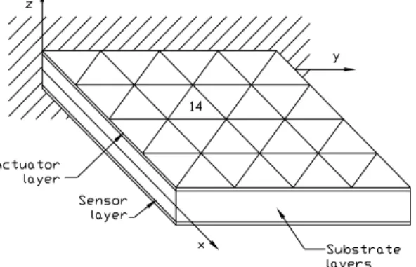
Assuming that piezoelectric sensors as well as actuators are bonded or embedded in the structure, as shown in Fig.1, the electric potential vector is subdivided in a sensor component
( )S
φ and an actuator component φ( )A .
Figure 1. A laminated composite plate with integrated piezoelectric sensor and actuators. The external applied electric charge at the sensors is zero. Separating the actuator and sensor components, the system of Eq. (27) take the following form:
[
Muu]{ } [
q&& + Kuu]{ }
q +[ ]
Ku(Sφ){ }
φ(S) ={
Fmecext (t)−Ku(Aφ) φ(A)}
(28)[ ]
K(A)φu{ }
q +[ ]
Kφφ(A){ } {
φ( )A = Fele(t)}
(29)From the last equation, the induced sensory electric potentials are obtained as follows: ) S ( φ ( )
{ }
φ S =−[ ] [ ]
Kφφ(S) −1 K(φSu){ }
q (31) The voltages induced in the sensors are not sufficient to have any appreciable effect onthe mechanical response through converse piezoelectric effect. The sensor output can be obtained in the following way. The charge output of each sensor, with poling in the z direction, can be expressed in terms of spatial integration of the electric displacement over its surface. Thus we have
∫ + ∫ = ∫ = + = = D (t )dA D (t )dA 2 1 dA ) t ( D ) t ( Q ) z z ( A z ) z z ( A z A z ) S ( 1 k k (32)
From Eq. (5), the last equation can be written as follows
dA e ) t ( Q T A ) S ( =
∫
ε (33)or in the discretised form
{ }
q[ ]
K{ }
q dA) ( ) t ( Q (S)u A mb T ) S ( φ = ∫ = e B (34)The current on the surface of the sensor is given by
dt dQ ) t ( I = (S) (35)
The output voltage of the amplifier turns out to be proportional to the sensor current, as
dt dQ Gc (S) ) S ( = φ (36)
where G = ( , resistance of the amplifier) is the constant gain of the amplifier, which transforms the sensor current to voltage.
c Ra
The sensor output voltage can be feed back through an amplifier to the actuator with a change of polarity. Thus, we have for the actuator voltage
dt dQ G Gi c (S) ) A ( =− φ (37)
whereGi is the gain of the amplifier to provide feedback control. The actuator voltage written in the discretised form, is then given by
[ ]
K{ }
q G Gi c (S)u ) A ( & φ − = φ (38)Use of Eq. (31) and Eq. (38) in Eq. (28) introduces an equivalent negative velocity feedback in the system as follows
[
Muu]{ }
q GiGc[ ] [ ]
K(uA) K(Su){ }
q[
Kuu]
[ ][ ] [ ]
K(uS) K(S) 1 K(Su) { }
q ={
Fmecext (t) − + − φ φ & φ φφ − φ &&}
(39)Considering Rayleigh type damping, we can write:
[
Muu] { } (
q CR CA){ }
q[ ]
Kuu[ ][ ] [ ]
Ku(S) K(S) 1 K(Su) { }
q ={
Fmecext (t)}
− + + + & φ φφ − φ && (40) with uu uu R M K C =α +β (41)where α and β are Rayleigh’s coefficients, and the damping effect due to the active control is given by:
[ ] [
(S) u ) A ( u c i A G G K K C =− φ φ]
(42)The solution of Eq. (35) is carried out using Newmark direct method of time integration, Newmark (1959), Bathe (1982).
5. NUMERICAL APPLICATIONS
5.1 Forced response with active feedback control of a simply supported plate.
A simply-supported square (axa) laminated plate, modeled by a (4x4) element mesh, (32 triangular elements) with lamination sequence
[
a/0º/90º/0º/s]
E1
, where a and s represent the piezoelectric actuator and sensor layers made of PVDF, bonded on upper and lower surfaces. The material properties of the substrate layers are: =172.5GPa, E2 =6.9 GPa,
, ρ=1600 kg/m GPA 45 . 3 G12 = E2 1= , 25 . 0 12 = ν GPa, 2 =
3. The material and piezoelectric properties of
PVDF are E G12=0.775GPa, ν12 =0.29, p33 =1.062 x 10⁻¹⁰F/m,e31 =e32 = 2 C/m 046 . 0 6 10 x 1 − = α 6 . 10 Gi =
, ρ=1800kg/m3. The side dimension is a = 0.18 m and the thickness of the
substrate layers and PVDF are 0.002 m and 0.0001 m, respectively. A time step ∆t=0.00015 s is used for the Newmark method, and Rayleigh type damping is considered, with coefficients
(rad/s) and β=0.965x10⁻⁵(rad/s)
q a / H E ( x 100 2 3 4
-1. The value of charge amplifier gain is
taken as 1 . The plate is initially subjected to a uniform distributed load q = 1000 N/m c G Ω 10 x 7 w
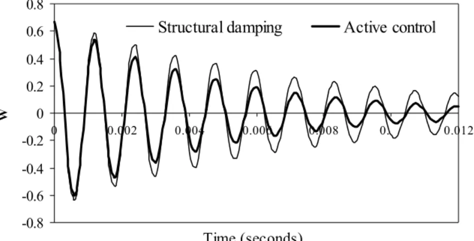
2 and then removed setting the plate in vibration. Figure 2 illustrates the response for
center deflection of the plate. The controlled response, with , clearly demonstrates the action of the piezoelectric actuator, which increases the overall damping of the system. Figure 3 and Fig. 4 show the sensed and input voltages of vibration of smart laminated plate, which are taken from element 14. We can observe that the
w )
0
sensed and input voltages vary as the beam vibrates, and their vibrational period is the same as the period of the laminated. Also we can see that there is about a π/2 phase difference between input and sensed voltages.
01 ontro 01 01 -0.8 -0.6 -0.4 -0.2 0 0.2 0.4 0.6 0.8 0 0.002 0.004 0.006 0.008 0. 0.012 Time (seconds) W
Structural damping Active control
Figure 2. Effects of structural damping and active control on the center deflection.
-0.50 -0.40 -0.30 -0.20 -0.10 0.00 0.10 0.20 0.30 0.40 0.50 0 0.002 0.004 0.006 0.008 0. 0.012 Time (seconds) Volts (V) Sensed voltage
Figure 3. The sensed voltage from the sensor layer
-500 -400 -300 -200 -100 0 100 200 300 400 500 0 0.002 0.004 0.006 0.008 0. 0.012 Time (seconds) Volts(V) Actuactor voltage
5.2 Forced response with active feedback control of a simply supported beam.
A simply supported graphite-epoxy composite beam, modeled by a (6x1) element mesh, (12 triangular elements), with lamination sequence
[
a/0º/90º/90º/0º/s]
GPA, 6 . 5 G12 , made up of four-layer, equal thickness, symmetric cross-ply, and two PVDF layers bonded to the upper and lower surfaces of the main structure, is considered. The mechanical and piezoelectric properties of the PVDF are the same of the previous application, and mechanical properties of the graphite-epoxy are E1=98GPa, E2 =7.9GPa, = ν12 =0.28,ρ=1520 kg/m3,
t=0.125x10⁻³ m. The beam is initially subjected to a uniform distributed load q = 140 N/m2.
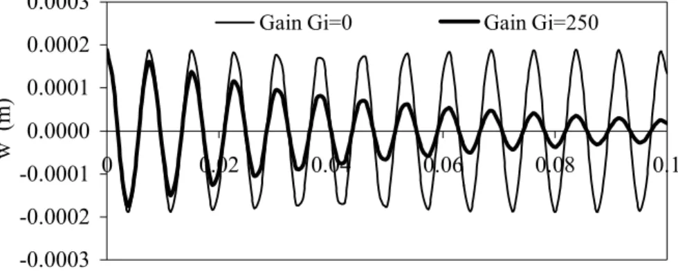
The beam dimension are length L=0.1 m and width b=0.005 m. A time step ∆t=0.00125 s is used for the Newmark method, and Rayleigh type damping is not considered. The value of charge amplifier gain G is taken as 1 . Figure 5 illustrates the response for center deflection w, where the effect of negative velocity feedback control is evident.
c .8 x 107Ω -0.0003 -0.0002 -0.0001 0.0000 0.0001 0.0002 0.0003 0 0.02 0.04 0.06 0.08 0.1 Time (seconds) w (m)
Gain Gi=0 Gain Gi=250
Figure 5. Effect of negative velocity feedback control on the center deflection
-4 -3 -2 -1 0 1 2 3 4 0 0.02 0.04 0.06 0.08 0.1 Time (seconds) Volts(V) Sensed voltage
Figure 6. The sensed voltage from the sensor layer
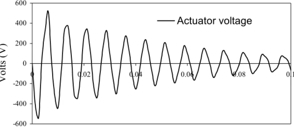
Figure 6 and Fig.7 show the sensed and input voltages of vibration of adaptive laminated beam, which are taken from element 6. From these two figures, we can observe that the sensed and input voltages vary as beam vibrates, and their vibrational period is the same as the period of the laminated. Also we can see, as in previous application, that there is about a
phase difference between input and output voltages.
2 / π
-600 -400 -200 0 200 400 600 0 0.02 0.04 0.06 0.08 0.1 Time (seconds) Volts (V) Actuator voltage
Figure 7. The input voltage on actuator layer 6. CONCLUSIONS
The active control capability of composite structures covered with piezoelectric layers is investigated, using the finite element method. A finite element model for active control of thin laminated structures with piezoelectric sensor and actuator layers, based on the Kirchhoff classical theory, has been developed. The present model has been validated in Moita et al. (2002), where the solutions for deflection and sensed voltage in a bimorph beam, are compared with the solutions obtained by other authors. Here, the results obtained, show that the negative velocity feedback control algorithm used in this model is effective for an active damping control of vibration response.
Acknowledgments
The authors thank the partial financial support of FCT/POCTI/FEDER, FCT-Proj. POCTI/P/EME/12028/1998, Phase II, and POCTI/2001/EME/37559.
REFERENCES
Allik, H. & Hughes, T., 1970, Finite element method for piezoelectric vibration, Int. J. Num. Meth. Engng., vol.2, pp. 151-157.
Bathe, K. J., 1982, Finite Element Procedures in Engineering Analysis. Prentice-Hall Inc, Englewood Cliffs, New Jersey, USA.
Benjeddou, A., 2000, Advances in piezoelectric finite element modeling of adaptive structural elements: A survey, Computer and Structures, vol. 76, pp. 347-363.
Bohua, S. & Huang, D., 2001, Vibration suppression of laminated composite beams with a piezo-electric damping layer, Composite Structures, vol. 53, pp. 437-447.
Crawley, E.F. & Luis, J., 1987, Use of piezoelectric actuators as elements of intelligent structures, AIAA Journal, vol. 25, n.10, pp.1373-1385.
Franco, V. M., Gomes, M. A. A., Suleman A., Mota Soares C. M., and Mota Soares C. A., 2000, Modelling and design of adaptive composite structures, Comp. Meth. Appl. Mech. Engineering, 185, pp. 325-346.
Lam, K.Y., Peng X. Q., Liu G R, and Reddy, J N., 1997, A finite element model for piezoelectric composite laminates, Smart Material Structures, 6, pp. 583-591.
Newmark, N.M., 1959, A method of computation for structural dynamics, Journal of Engineering Mechanics Division, vol. 3, pp. 67-94.
Moita, J.S., Mota Soares, C.M. and Mota Soares, C.A., 2002, Geometrically non-linear analysis of composite structures with integrated piezoelectric sensors and actuators, Composite Structures, vol. 57, n.1- 4, pp. 253-261.
Reddy, J. N., 1999, On laminate composite plates with integrated sensors and actuators, Engineering Structures, vol. 21, pp. 568-593.
Samanta, B., Ray M. C., and Bhattacharyya R., 1996, Finite element model for active control of intelligent structures, AIAA Journal, vol. 34, n. 9, pp.1885-1893.
Senthil, V. G., Varadan, V. V., and Varadan, V. K., 1999, A review and critique of theories for piezoelectric laminates, Smart Material Structures, vol. 9. pp. 24-28
Tiersten, H. F., 1969, Linear Piezoelectric Plate Vibrations, Plenum Press, New York.
Zienckiewicz, O. C., 1977, The Finite Element Method in Engineering Sciences, McGraw- Hill, 3 rd, London.