_____________________________________ 978-1-5386-1069-5/17/$31.00 ©2017 IEEE
High Performance Position Control of Permanent
Magnet Synchronous Drives
Antonio Pesántez1,2, *, Luís Neves1,3, Rodrigo Sempértegui2
1 School of Technology and Management, Polytechnic Institute of Leiria, Leiria, Portugal
2 Electrical and Electronics Engineering Department, University of Cuenca, Cuenca, Ecuador
3 INESC Coimbra, Coimbra, Portugal
* Corresponding Author, email: [email protected]
Abstract— In the design and test of electric drive control systems, computer simulations provide a useful way to verify the correctness and efficiency of various schemes and control algorithms before the final system is actually constructed, therefore, reducing development time and associated costs. Nevertheless, the transition from the simulation stage to the actual implementation has to be as straightforward as possible. This paper presents the design and implementation of a position control system for permanent magnet synchronous drives using the dsPIC33FJ32MC204 microcontroller as the target processor to implement the control algorithms. The overall system is simulated and tested in Proteus VSM software which is able to simulate the interaction between the firmware running on the microcontroller and the analogue circuits connected to it. The electric drive model is developed using elements present in the Proteus VSM library. As in any high-performance AC electric drive system, field oriented control is applied. The complete control system is distributed in three control loops, namely torque, speed and position. A standard PID control system, and a hybrid control system based on fuzzy logic, are implemented and tested. The natural variation of motor parameters, such as winding resistance and magnetic flux, are also simulated. Comparisons between the two control schemes are carried out for speed and position control using different error measurements, such as, integral square error, integral absolute error and root mean squared error. Comparison results show a superior performance of the fuzzy-logic-based controller when coping with parameter variations, and by reducing torque ripple, but the results are reversed when periodical torque disturbances are present.
Keywords—electric drives prototyping; permanent magnet machines; position control; Proteus VSM, dsPIC30F/33F, fuzzy controllers.
I. INTRODUCTION
Advances in microprocessor technologies and embedded systems have made possible implementations of complex control algorithms which requires intensive math computations. Moreover, the recent development in power electronics and semiconductor devices have given a way for AC motor drives to be used instead of DC drives, in high-performance applications. The permanent magnet synchronous motor (PMSM) has gained an important place in applications where high-performance speed and position control are required. Characteristics such as high mass-power ratio, high torque-inertia ratio, high power density, high efficiency, reduced
maintenance, etc., make the PMSM an interesting choice in applications such as industrial robots, CNC milling machines, electric vehicles, wind turbines, etc. [1] [2] [3].
A widely used control method in high-performance AC drives is field oriented control, also known as vector control. This approach allows to regulate the three-phase AC machine currents by controlling the current space vector in the rotating reference frame, making the control similar to that of the separately exited DC machine, but maintaining all the benefits of AC machines [4].
The overall performance of an electric drive will depend not only on the accuracy and speed of the control, but also on the robustness of the controller to operate correctly even if there are significant external disturbances, uncertainties in motor parameters, and lack of precise mathematical models.
This paper deals with the design and implementation of a PMSM drive control system, considering two types of controllers namely: a PID-based controller and a hybrid controller based on fuzzy logic. The PMSM drive is simulated and tested through the software Proteus VSM, using the dsPIC33FJ32MC204 as the target processor. Simulation models for stator resistance and permanent magnet flux variations are also presented.
II. LITERATURE REVIEW
Machine parameters change dynamically with temperature variations, magnetic saturations, skin effect, etc. These changes may affect the performance of an electric drive. To deal with these drawbacks, various nonlinear control techniques such as sliding mode controllers, fuzzy-logic controllers, adaptive controllers, and hybrid controllers have been developed in recent years. Some of these non-linear control techniques, applied to control PMSM drives, are reviewed in this section.
A. Model Reference Adaptive Control
The idea behind the model-reference adaptive control technique is to develop a closed loop controller with parameters that can be modified to change the response of the system. The desired response of the process to a signal input is specified as a reference model. The output of the process is compared with the output of the reference model to generate an error signal. An adaptation mechanism looks at this error and calculates the adequate parameters for the main controller in order to minimize the error. Lyapunov’s stability and Popov’s hyperstability theories are standard design methods for the control law in adaptive control systems.
A model reference adaptive controller applied to control position on a PMSM have been proposed by Liu Mingji et al. [5]. The experimental results show a satisfactory performance of the electric drive despite uncertainties and parameter variations.
B. Fuzzy Logic Model Reference Adaptive Control
Basically, Fuzzy Logic is a multilevel logic which allows to define intermediate values when evaluating a statement. It is an attempt to catch and represent the human knowledge. In fuzzy logic, an affirmation can be truth for many degrees of truth, from completely true to completely false [6].
Nowadays, fuzzy logic is widely applied in control systems. A fuzzy logic controller will use fuzzy membership functions and inference mechanisms to determine the appropriate control signal. Fuzzy-logic-based controllers are usually applied together with other types of controllers/systems to achieve better performances [7].
Ying-Shieh Kung and Pin-Ging Huang [8], have presented a high-performance position controller for PMSM using a fuzzy-logic controller in the position control loop with and adaptation mechanism based on the gradient method. The overall system, including the adaptive controller and the SVPWM scheme were implemented in a TMS320F2812 DSP chip taking advantage of it power processing and peripheral availability, and experimental results demonstrated that in step command response and frequency command response, the rotor position can fast track the prescribed dynamic response, thus, obtaining a high-performance position controller for PMSM. C. Sliding Mode Control
Sliding mode control is a nonlinear control method whose purpose is to alter the dynamic of a nonlinear system applying a discontinuous control signal that force the system to “slide” along a defined state-space trajectory. The intrinsic discontinuous characteristic of the sliding mode allows a simple control that can be designed to switch between only two states (on/off) without a precise definition, therefore, adding robustness against parameter variations [9].
Fadil Hicham et al. [10], present a velocity control of PMSM based on the sliding-mode and a fuzzy-logic system for chattering minimization. The proposed system was tested by means of computer simulations using the software tool PLECS integrated with MATLAB/Simulink. The controller was implemented in a eZdspF28335 board using MATLAB/Simulink rapid prototyping to control an 80W PMSM. Results confirmed the effectiveness of the fuzzy-logic sliding mode controller to reduce the chattering effect and to cope with uncertainties.
D. Hybrid Non-Linear Control
Various control techniques can be applied together in order to obtain an enhanced control performance. A hybrid position controller for PMSM conformed by three main controllers namely, an adaptive fuzzy-logic-neural-network controller, a robust controller and an auxiliary controller based on the sliding mode had been proposed by Fayez F.M. El-Sousy [11]. This complex controller is designed in order to guarantee stability and high-performance operation of the PMSM, and to eliminate the
need of having a prior knowledge of the constrain conditions of the system, thus, increasing the portability of the controller to other nonlinear dynamic systems. The adaptive hybrid controller was applied to the position loop, skipping the velocity loop and thus, giving the torque reference directly to the current/torque controller. The experimental results successfully confirmed that the proposed adaptive hybrid control system grants robust performance and precise dynamic response to the reference model regardless of the PMSM parameter variations and load disturbances.
The above referenced works present various non-linear control methods which can be applied to cope with uncertainties and parameter variations in PMSM electric drive systems. Nevertheless, the controller’s complexity, the required processing power to implement the control algorithms, and the associated costs have to be taken into account when implementing electric drive control systems.
III. ELECTRIC DRIVE MODEL
A. PMSM Model
The dynamic behavior of the PMSM, in the d-q reference frame, is governed by the following equations [12]
= 1 − + (1) = 1 − − − (2)
= 3
2 − − (3)
Where
is the electrical angular frequency
, are the d-axis and q-axis currents respectively , are the d-axis and q-axis voltages respectively , are the d-axis and q-axis inductances respectively is the stator resistance
is the permanent magnet flux linkage is the number of pole pairs
is the total inertia is the viscous friction is the load torque
The electrical speed is related with the mechanical speed by =
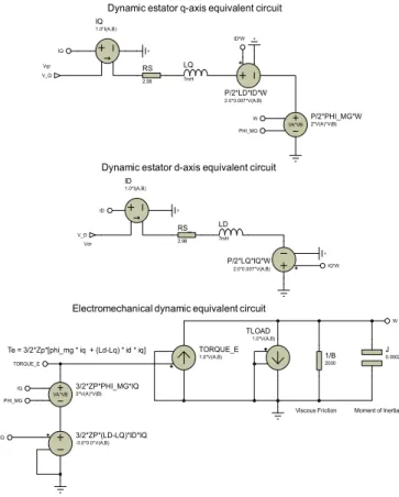
The machine model in the d-q reference frame is implemented in Proteus using controlled voltage/current sources, and discrete elements (resistors, inductors, capacitors). Figure 1 shows this implementation.
The three-phase model of the PMSM is obtained applying reference frame transformation circuits. The three-phase input voltage is converted to a bi-phase voltage source in the fixed α-β reference frame (Clarke’s transformation). Since the machine model is developed in the rotating reference frame, the α-β to d-q transformation (Park’s transformation) must be applied.
Figure 1. Proteus model of the PMSM in the d-q reference frame The d-q currents obtained from the model are transformed to the three-phase fixed reference frame applying the corresponding inverse transformations (inverse Parks’ and inverse Clark’s transformation), thus, completing the three-phase machine model.
The Proteus implementation of the required Clarke’s and Parke’s transformations are carried out using voltage controlled voltage sources and multiplier voltage sources. The implemented equations are:
for Clarke’s transformation
= = 1
√3 + 2 √3
for Park’s transformation
= cos( ) + sin ( ) = cos( ) − sin ( )
for inverse Park´s transformation
= cos( ) − sin ( ) = cos( ) + sin ( ) for inverse Clarke’s transformation
= = −1 2 + √3 2 = −1 2 − √3 2 B. Inverter Model
The inverter is simulated considering the following equations
This simplified representation of a three-phase inverter is used in order to reduce computational load and required simulation time.
C. Signal Conditioning Circuits for dsPIC33FJ32MC204 The signal conditioning circuits are not directly implemented in Proteus because the unnecessary computational load added. Instead, voltage controlled voltage sources with the appropriate multiplication factors are used to adequate the signal levels to the microcontroller inputs.
The dsPIC33FJ32MC204 was selected as the target processor to implement the control algorithms because of its peripheral availability for motor control applications, such as, PWM module with center-aligned mode, ADC module with 500ksps sampling rate, quadrature encoder interface, etc.
IV. CONTROLLERS DESIGN
The PMSM electric drive control system is designed with three control loops, namely current/torque, speed and position. PI controllers with feedforward compensation are designed for the current/torque loop. A PI controller, as well as a fuzzy tuned PI controller are designed for the speed loop. Finally, a proportional controller and a fuzzy-logic controller are designed for the position loop.
A. PI Current Controller
The first control loop required for any high-performance drive control system is the current/torque loop. In this loop, the d-axis and the q-axis currents of the PMSM are regulated using PI controllers. Figure 2 presents a block diagram of the current control loop for a PMSM.
As can be seen in the PMSM mathematical model presented in equations (1), (2) and (3), there are nonlinear cross-coupling terms in the differential equations for the d-q currents. These cross-coupling terms can be eliminated with an input-and-output linearization and feedforward manipulation [12]. Using the auxiliary variables , defined such that
1
= 1 + 1
= 1 − −
By replacing the above equations into the PMSM model equations (1) and (2), the following first order differential equations are obtained
= − + 1 = − + 1 LD 7mH P/2*LQ*IQ*W 2.0*0.007*V(A,B) ID IQ*W Vdr
Dynamic estator d-axis equivalent circuit
V_D ID 1.0*I(A,B) RS 2.98 LQ 7mH P/2*LD*ID*W 2.0*0.007*V(A,B) IQ ID*W Vqr
Dynamic estator q-axis equivalent circuit
V_Q IQ 1.0*I(A,B) TORQUE_E 1.0*V(A,B) 1/B 2000 J 0.0002 3/2*ZP*(LD-LQ)*ID*IQ -3.0*0.0*V(A,B) ID*IQ
Electromechanical dynamic equivalent circuit
Te = 3/2*Zp*[phi_mg * iq + (Ld-Lq) * id * iq]
Viscous Friction Moment of Inertia TLOAD 1.0*V(A,B) W TORQUE_E RS_ 2.98 VA*VB P/2*PHI_MG*W 2*V(A)*V(B) W PHI_MG
VA*VB 3/2*ZP*PHI_MG*IQ3*V(A)*V(B) IQ PHI_MG = 3 (2 − − ) = 3 (2 − − ) = 3 (2 − − )
The Laplace transfer functions of the above equations are ( ) ( )= 1 + ( ) ( )= 1 +
Whit these first-order plant models, the PI current controllers are parametrized using pole-placement. The PI controller parameters for the d-axis current are
=2 1−
=2 −
and for the q-axis current
= 2 − 1 (4) = 2 − (5)
The damping coefficient is selected to be 0.707 or 1. The natural frequency determine the desired closed-loop settling time, which also correspond to the desired bandwidth of the closed-loop system. Therefore, the larger is, the shorter the desired closed-loop settling time is.
Selecting relative to the bandwidth of the open-loop system and using a normalized parameter 0 < < 1, the parameter is calculated as
= 1 1 −
for the d-axis current control, and for the q-axis current control
= 1 1 −
As the normalized parameter gets closer to 1, tends to ∞. The parameter is selected around 0.8 or 0.9 in order to obtain a fast response.
With the controller parameters calculated, the voltage control signals will be
Where = ∗− = ∗− = − = + B. PI Speed Controller
Rewriting the speed differential equation (3) as
= − +3
2 −
and applying the Laplace transformation to get the relationship between the angular velocity and the q-axis current
+ Ω ( ) =3 2 ( ) Ω ( ) ( ) = 3 2 +
Now, replacing in the q-axis current differential equation (2) with the value given by the PI current controller, and assuming cancelation of the nonlinear terms, the following differential equation is obtained
= − + 1 ∗− + ∗( ) − ( )
Taking the Laplace transformation of the above equation leads to ( ) = − ( ) + ∗( ) − ( ) + ∗( ) − ( ) ( ) ∗( )= + + + +
The following identities are obtained from equations (4) and (5) of the q-axis current controller design
= = 2 −
Applying the above identities, the transfer function from the q-axis reference current to the actual q-q-axis current is given by
( ) ∗( )= 2 − + + 2 + = + ( ) + = + ( ) +
Figure 4. Input membership functions for the fuzzy-tuned PI speed controller
Using the above transfer function together with equation (3), the relationship between the reference q-axis current ∗( ), and the electrical speed Ω ( ) is given by
Ω ( ) ∗( ) = 3 2 + 2 − + + 2 +
In order to design a PI controller using the pole-placement approach, a first-order plant model is required. Therefore, the above transfer function needs to be approximated by a first order model.
If the natural frequency is chosen to be much greater than the mechanical relationship , the inner current-loop dynamics can be neglected, leading to an approximate first order model given by Ω ( ) ∗( ) ≈ 3 2 +
Applying the pole-placement design technique, the PI controller parameters for the speed loop are calculated as follows
=2 − 3 2 =2 −
C. Proportional Position Controller
The position controller consists of a simple proportional controller plus a feedforward speed signal calculated as the derivative of the reference angular position. The control action of the proportional controller, which is the speed reference signal, is calculated with the following equation
∗= ( ∗− ) + ∗
where
∗= ∗
D. Fuzzy Tuned PI Speed Controller
The use of a fuzzy inference system can be adopted to determine the values of the PI speed controller parameters during the transient response in order to decrease the rise time and reduce the overshoot [13].
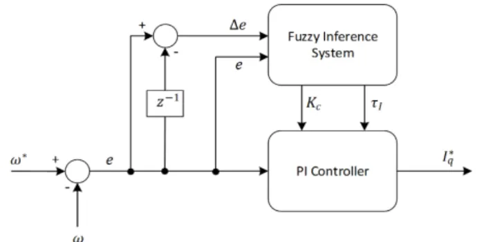
A schematic diagram of the proposed fuzzy-tuned PI speed controller is presented in figure 3
As can be seen in the block diagram, the fuzzy inference system has two inputs which are the error and the error variation, and has two outputs corresponding to the proportional and integral parameters of the PI speed controller.
Five triangular-shaped membership functions with 50% overlap, are applied for each input and output of the fuzzy inference system. The membership functions are symmetrically distributed along the corresponding universe of discourse, which is stablished according to the process operating ranges. The same universe of discourse is applied for the error and the error variation, and a normalized universe of discourse is used for the outputs.
The names for the input membership functions are defined as follows: NB = Negative Big N = Negative Z = Zero P = Positive PB = Positive Big
The membership functions for the inputs are shown in figure 4
The names for the output membership functions are defined as follows VS = Very Small S = Small M = Medium L = Large VL = Very Large
Figure 7. Input membership functions of the fuzzy-logic position controller
The output values will be the proportional and integral parameters of the PI speed controller, designated as and respectively. Figure 5 shows the output membership functions
A Mamdani-type fuzzy inference system is applied. The minimum operation is used as the ‘AND’ method for fuzzy implication, and the maximum operation is applied for the union of all outputs.
The rule base is stablished based on the knowledge acquired from the performed computer simulations for the standard PI speed controller, where the following facts were identified An increment in :
- Increase the rise time - Reduce overshoot
- Increase ripple in steady state
- Reduce the amplitude of torque disturbances An increment in = Δ :
- Reduce the rise time - Increase overshoot
- Increase ripple in steady state
- Reduce the area of torque disturbances
The behavior of the speed response according to the signs of the error and the error variation is described as follows
- When is positive and Δ is positive, then the speed gets closer to the reference signal
- When is positive and Δ is negative, then the speed moves away from the reference signal - When is negative and Δ is positive, then
the speed moves away from the reference signal - When is negative and Δ is negative, then
the speed gets closer to the reference signal
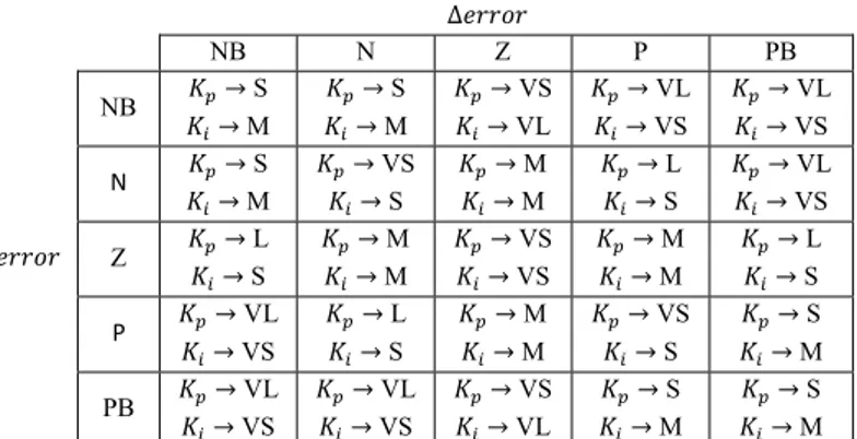
In short, when error and error variation have the same sign, the speed gets closer to the reference signal and vice versa. Based on the above information, the rule base for the fuzzy-tuned PI speed controller is defined as described in Table 1.
The weighted average defuzzification method is applied to find the crisp output value. Mathematically, this method is defined as
=∑∑ [ ] [ ] [ ]
where [ ] is the center value of the individual k-output membership function, and [ ] is the corresponding membership value. Δ NB N Z P PB NB → S → M → S → M → VS → VL → VL → VS → VL → VS N → S → M → VS → S → M → M → L → S → VL → VS Z → L → S → M → M → VS → VS → M → M → L → S P → VL → VS → L → S → M → M → VS → S → S → M PB → VL → VS → VL → VS → VS → VL → S → M → S → M
Table 1. Rule-base for the fuzzy-tuned PI speed controller E. Fuzzy-Logic Position Controller
Considering a PMSM position controller with the intermediate speed controller, the inputs for the position controller are selected to be the error and the variation of the error, and the output will be the reference angular speed. A scaling factor is applied for each signal. Figure 6 presents a schematic diagram of the proposed direct fuzzy-logic controller.
Seven triangular-shaped membership functions with 50% overlap, are applied for each input and output of the fuzzy controller. The membership functions are symmetrically distributed along the corresponding universe of discourse, which is stablished according to the process operating ranges. The same universe of discourse is applied for the error and the variation of the error, and a normalized universe of discourse is used for the output. The names for the membership functions are defined as follows
NB = negative big NM = negative medium NS = negative small Z = zero PS = positive small PM = positive medium PB = positive big
The membership functions for the inputs are shown in figure 7. Figure 5. Output membership functions for the fuzzy-tuned PI
speed controller
Figure 8. Output membership functions of the fuzzy-logic position controller
Figure 9. Fuzzy-logic position controller with proportional action The membership functions for the output, with a normalized universe of discourse, is presented in figure 8
A Mamdani-type fuzzy inference system is applied. The minimum operation is used as the ‘AND’ method for fuzzy implication, and the maximum operation is applied for the union of all outputs.
The rule-base of the fuzzy controller relates the error and the error variation to obtain a consequent output. The linguistic fuzzy rules are based on the Macvicar-Whelan matrix described in Table 2.
The weighted average defuzzification method is applied to find the crisp output value.
∆ NB NM NS Z PS PM PB NB NB NB NB NB NM NS Z NM NB NB NB NM NS Z PS NS NB NB NM NS Z PS PM Z NB NM NS Z PS PM PB PS NM NS Z PS PM PB PB PM NS Z PS PM PB PB PB PB Z PS PM PB PB PB PB
Table 2. Rule-base for the fuzzy-logic position controller In order to improve the position controller response at steady-state, an error proportional factor is applied to the output of the controller. With this scheme, the control action strength is reduced as the position gets closer to its reference value and thus, the oscillations at steady-state are reduced. The block diagram of the proposed controller is presented in figure 9.
The output of this controller will be ∗=
The output scaling factor and the proportional constant have to be properly parametrized in order to maintain the effect of the fuzzy-logic controller output in the final control action. In general terms, the output scaling factor of the fuzzy controller has to be selected much bigger that the proportional constant.
V. PARAMETERS VARIATION
Machine parameters will vary during normal operation, principally due to temperature variations. Stator resistance and permanent magnet flux are the most affected parameters. In order to observe the effects of these parameter variations, resistance and flux step changes are added in the Proteus PMSM model.
A. Stator Resistance Variation
Since the stator resistance sensitivity is overcome in the current control loop, a considerable step variation is required to observe the effects of resistance variation. Using a voltage controlled switch in Proteus, a resistor with approximately 200% of the nominal stator resistance value is placed in series with the nominal resistance of the machine. Figure 10 shows this implementation in the − model of the PMSM.
Figure 10. Stator resistance step variation model
According to figure 10, ‘R_STEP’ added in series with the stator resistance is controlled by the voltage controlled switch. The switch is initially closed, thus, only the nominal resistance value is effectively placed in the model. When the switch is open, a stator resistance increase is produced. In this way, a step resistance variation is simulated.
B. Permanent Magnet Flux Variation
The effect due to the loss of magnetism with temperature variations is predominant compared to the effect of stator resistance variation on the performance of the drive system. The sensitivity of residual flux density in magnets for 100ºC rise in temperature in ferrite, neodymium and samarium cobalt magnet are -19%, -12% and -3%, respectively, from their nominal values [14]. LD 7mH Zp*Lq*V(A,B) ID IQ*W Vdr V_D 1.0*I(A,B) RS 2.98 LQ 7mH Zp*Ld*V(A,B) IQ ID*W Vqr V_Q 1.0*I(A,B) R6 2.98 VA*VB Zp*V(A)*V(B) W PHI_MG RQ_STEP 6 VSWITCH R_STEP RD_STEP 6 R_STEP
Figure 13. PI speed controller test
Figure 14. Fuzzy-tuned PI speed controller test A ferrite magnet is considered, so a -19% step flux variation
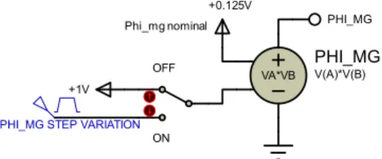
will be used in the simulation. For the Proteus implementation, the nominal value of the permanent magnet flux linkage is passed through a voltage multiplier. The first factor of the multiplier will be the nominal flux linkage value. The second factor of the multiplier is connected to a switch for enabling or disabling the flux step variation. The implementation is presented in figure 11.
When the switch is in the ‘off’ position, the multiplier factor is 1 and thus, the nominal value of the permanent magnet flux linkage is taken. When the switch is placed in the ‘on’ position, a step signal with amplitude equal to 0.81 (corresponding to a -19% variation) is selected as the multiplier factor.
VI. CONTROLLERS TEST
All the controller parameters are further tuned via simulation in order to achieve approximately the characteristics presented in table 3.
Control Loop Bandwidth Control Sampling
Frequency
Current 900Hz 16kHz
Velocity 50Hz 4kHz
Position 10Hz 1kHz
Table 3. Bandwidths and frequencies of the PMSM control loops The bandwidth is estimated using the rise time with the following formula
=0.35
The control sampling frequency is configured upon the base of the PWM frequency using the PWM interrupt period of the dsPIC33FJ32MC204. Counter variables that divide the PWM interrupt period are used to obtain the corresponding sampling frequency for velocity and position.
A. Current Control Loop
The PI current controller is implemented and tested in Proteus. Setting the q-axis reference current at 1A and the d-axis reference current at 0A. The simulation result is presented in figure 12.
B. PI Speed Controller
The PI speed controller is tested setting a reference of 100 rad/s. The simulation result is presented in figure 13. The y-axis is configured to display the speed response starting from 95 rad/s.
C. Fuzzy-Tuned PI Speed Controller
The fuzzy-tuned PI controller is tested with the same graph configurations as for the standard PI controller. The simulation result is presented in figure 14.
As can be seen, the fuzzy-tuned PI speed controller has less ripple in the steady-state response compared with the conventional PI controller. +0.125V PHI_MG VA*VB PHI_MG V(A)*V(B) +1V Phi_mg nominal
PHI_MG STEP VARIATION
OFF
ON
Figure 11. Permanent magnet flux step variation model
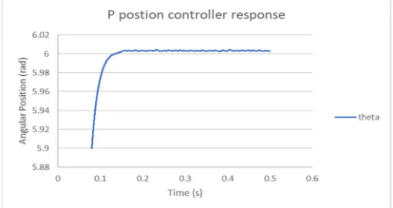
Figure 15. Response of proportional position controller
Figure 16. Response of fuzzy-logic position controller with proportional action
Figure 17. Comparison of speed controllers using bar charts
D. Proportional Position Controller
The proportional position controller is tested configuring the y-axis graph to display starting from 5.9 radians, for a command reference signal of 6 radians. The position response is presented in figure 15.
E. Fuzzy-Logic Position Controller with Proportional Action The fuzzy-logic position controller with proportional action is tested under the same graph configurations as for the standard proportional controller. Figure 15 shows the position response for this controller. By comparing the responses of figures 14 and 15, an improve in the steady state response can be observed for the fuzzy-logic controller with proportional action. In terms of rise time, both controllers have similar performances.
VII. CONTROLLERS COMPARISON
The standard PID-based and the fuzzy-logic-based controllers are compared by means of error indicators namely integral square error, integral absolute error and root mean squared error. These error measurements are described by the following equations
• Integral square error
=
• Integral absolute error
= | |
• Root mean square error
= 1
−
The comparison is carried out for speed control and for position control. In order to test the performance of the controllers, four different conditions are considered for simulation, which are:
a) No disturbance or perturbation
b) Periodical torque disturbance with 100ms period c) 200% stator resistance variation step
d) -19% permanent magnet flux variation step A. Speed Controllers Comparison
The standard PI speed controller, and the fuzzy tuned PI speed controller are simulated according to the conditions described previously. To facilitate comparison, the resulting data are plotted as bar charts, and presented in figure 17.
Figure 18. Comparison of position controllers using bar charts
A general view of the above data shows that the fuzzy-logic-based speed controller has better performance compared with the standard PID-based speed controller. Although for a periodic torque disturbance the standard PI speed controller outperforms the fuzzy-tuned PI controller.
B. Position Controlles Comparison
As for the speed controllers, the standard proportional position controller, and the fuzzy-logic position controller, are simulated taking into account all the simulation conditions described previously. The resulting data are plotted as bar charts, and presented in figure 18.
As can be seen in the bar charts, for the periodical torque disturbance condition, the error for the fuzzy-logic position controller is bigger than the error for the standard proportional controller. Nevertheless, the opposite occurs for the rest of conditions. Another point to be noted are the error magnitudes which are lesser than 0.005 for a 6 radians reference (error < 0.08%), suggesting a good performance for both controllers.
CONCLUSIONS
Fuzzy-logic systems have many advantages over the conventional controllers. For instance, fuzzy-logic controllers can handle non-linearities, do not require precise mathematical models, and work based on the intuition and experience of the human operator. Therefore, fuzzy inference systems can be applied to improve the performance of standard PID controllers, either modifying and dynamically tuning the PID-gain parameters, or directly implementing a fuzzy-logic controller.
A fuzzy-tuned PI speed controller was implemented in this work, presenting an improved performance in torque-ripple reduction and when coping with parameter variations, when compared with the standard PI controller. Similar results were obtained for the implemented fuzzy-logic position controller. Nevertheless, a simulation with an applied periodical torque disturbance of considerable amplitude (about 70% of the machine rated torque) showed a superior performance of the standard controllers over the fuzzy-logic ones.
Computer simulations of control systems can reduce development time when the transition between the simulation stage to the actual implementation is straightforward. Proteus VSM software was used to simulate a PMSM control system, directly implementing the control algorithms in a microcontroller, therefore, helping to reduce the time required for a real-world implementation.
The practical validation of the proposed controllers is currently being implemented. The speed controllers were already tested physically, although for a brushless DC motor, and the obtained results are consistent with the simulations.
ACKNOWLEDGMENTS
This work was partially supported by the Portuguese Foundation for Science and Technology under grant Pest-OE/EEI/UI308/2014
The first author would like to thank SENESCYT and Polytechnic Institute of Leiria for the given opportunity to obtain his master’s degree.
REFERENCES
[1] Jacek F. Gieras, Permanent Magnet Motor Technology Design and Applications, Third. CRC Press, 2010. [2] Adel El Shahat and Hamed El Shewy, “Permanent Magnet
Synchronous Motor Drive System for Mechatronics Applications.” IJRRAS, Aug-2010.
[3] Minoru Kondo, “Application of Permanent Magnet Synchronous Motor to Driving Railway Vehicles.” Railway Technology Avalanche, 01-Jan-2003.
[4] Haitham Abu-Rub, Atif Iqbal, and Jaroslaw Guzinski, High Performance Control of AC Drives with Matlab/Simulink Models, First. John Wiley & Sons, 2012. [5] Liu Mingji, Cai Zhongqin, Cheng Ximing, and and
Ouyang Minggao, “Adaptive Position Servo Control of Permanent Magnet Synchronous Motor.” 2004 American Control Conference, Boston, Massachusetts, Jul-2004. [6] Zdenko Kovacic and Stjepan Bogdan, Fuzzy Controller
[7] Timothy J. Ross, Fuzzy Logic With Engineering Applications, Third. John Wiley & Sons, 2010.
[8] Ying-Shienh Kung and Pin-Ging Huang, “High Performance Position Controller for PMSM Drives Based on TMS320F2812 DSP.” IEEE International Conference on Control Applications, Taipei, Taiwan, Sep-2004. [9] Wilfrid Perruquetti and Jean Pierre Barbot, Sliding Mode
Control in Engineering. Marcel Dekker, Inc., 2002. [10] Fadil Hicham, Driss Yousfi, Aite Driss Youness,
Elhafyani Mohamed Larbi, and Nasrudin Abd Rahim, “Sliding-Mode Speed Control of PMSM with Fuzzy-Logic Chattering Minimization, Design and Implementation.” MDPI Open Access Journals, 2015.
[11] Fayez F.M. El-Sousy, “Adaptive hybrid control system using a recurrent RBFN-based self-evolving fuzzy-neural-network for PMSM servo drives.” ELSEVIER, Applied Soft Computing, 2014.
[12] Liuping Wang, Shan Chai, Dae Yoo, Lu Gan, and Ki Ng, PID and Predictive Control of Electrical Drives and Power Converters using MATLAB/Simulink, First. John Wiley & Sons, 2015.
[13] Antonio Visioli, Practical PID Control. Springer, 2006. [14] R. Krishnan, Permanent Magnet Synchronous and